1
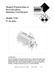
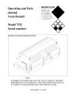
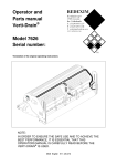
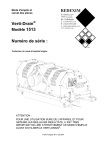
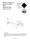
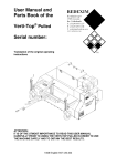
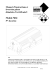
Operator / Technical
and (Parts) manual
Verti-Drain®
Redexim
Model 7007
Serial number:
NOTE:
IN ORDER TO ENSURE THE SAFE USE AND TO ACHIEVE THE BEST
PERFORMANCE, IT IS ESSENTIAL THAT THIS OPERATORS
MANUAL IS CAREFULLY READ BEFORE THE VERTI-DRAIN IS
USED.
Product manual code 911.120.400
Updated 04/01
FOREWORD
Congratulations on the purchase of your VERTI-DRAIN. To ensure the safe and lasting operations of
this VERTI-DRAIN you (and anyone using the machine) should read and understand this users
manual. A complete knowledge of the contents of the manual is necessary in order to ensure the safe
use of this machine.
The VERTI-DRAIN is intended exclusively for grass fields or areas on which grass can grow.
On the following page, we will begin with the safety instructions. Every user must be familiar with
these instructions and must follow them carefully. Below you will find a registration card, which
should be returned to us so that we are able to process any future claims.
In this manual, many instructions are given which are stated in a number sequence. The user must
follow the instructions according to this sequence. If the * appears this refers to safety instructions. If
the @ is used, this refers to a tip and/ or note.
GUARANTEE CONDITIONS
THIS VERTI-DRAIN PRODUCT IS DELIVERED TO THE CUSTOMER ACCOMMPANIED BY
A GUARANTEE AGAINST DEFECTS IN THE MATERIALS USED. THIS GUARANTEE
APPLIES FOR A PERIOD OF 12 MONTHS AS OF THE DATE OF PURCHASE.
VERTI-DRAIN GUARANTEES ARE SUBJECTED TO THE "GENERAL CONDITIONS FOR
SUPPLY OF PLANT AND MACHINERY FOR EXPORT, NUMBER 188", WHICH ARE
PUBLISHED UNDER THE AUSPICES OF THE UNITED NATIONS ECONOMIC COMMISSION
FOR EUROPE.
REGISTRATION CARD
For your own record, copy the information from the registration card to the table hereunder
Serial number of machine
Name of your distributor
Date of purchase
Any remarks
2
SAFETY INSTRUCTIONS
1.
Never disconnect or shortcut any of the safety switches.
2.
The VERTI-DRAIN can be used as a sit-on and walk-in front unit. We strongly
advise to transport the machine whilst sitting on the unit (gear 4,5 or 6) and to walk
in front when working (gear 1,2 and 3) with the VERTI-DRAIN.
3.
The VERTI-DRAIN is suited exclusively to grass fields.
4.
Every VERTI-DRAIN user must be fully informed of the information contained in
the user manual.
5.
Inspect the ground where the VERTI-DRAIN is to be applied. Remove loose
obstacles, avoid uneven ground.
6.
Never step off the unit if the engine is still running.
7.
Ensure that other people are standing at least 4 mtr. (14' ) away from the VERTIDRAIN.
8.
Use appropriate clothing. Wear strong shoes with a steel inforced toe cap, long
trousers, tie up long hair. Do not have any loose pieces of clothing.
9.
Never try to force the VERTI-DRAIN, a situation which is visible in the partial
loosening of the front roller from the ground and unstable behavior of the VERTIDRAIN.
10.
Check the VERTI-DRAIN once a week to ensure there are no loose screws or nuts
and bolts.
11.
The VERTI-DRAIN may never be used without protection covers and safety
stickers.
12.
NEVER crawl underneath the VERTI-DRAIN.
13.
Always switch off the engine, before starting any maintenance, adjustment or repair.
Also block the VERTI-DRAIN against sinking and block it against forward/backward
movement or sliding.
14.
Use only the original VERTI-DRAIN spare parts/ tines in order to ensure the safe
operation of the machine.
15.
Never use the VERTI-DRAIN in the dark, in heavy rain, on frozen ground, stormy
conditions or on slopes greater than 20 degrees.
16.
Before operating the machine, also read the instructions and the maintenance
information for the Honda engine. This component has its own certification mark.
17.
Maintain a log book of repairs.
18.
If any modifications are carried out on the machine the CE certification mark will
be no longer valid. The User/Dealer himself must then have the machine re-certified.
19.
The unit can not be used on public roads
20.
Wear certified ear protection, against the noise
3
CONTENTS
Par.
Description
Page
Foreword
2
Guarantee conditions
2
Registration card
2
Safety instruction
3
1.0
Technical specification
5
2.0
First setup
6
3.0
General controls
8
4.0
Working depth adjustment
9
5.0
Tine angle adjustment
10
6.0
Start/ stop procedures
10
7.0
General usage of Verti-Drain
11
8.0
Transport of Verti-Drain
12
9.0
Problem analysis
12
10.0
Maintenance
13
11.0
Weight transfer system
14
12.0
EU Declaration
14
13.0
Technical items
15
13.1
Rear wheel chain drive
15
13.2
Reversing safety switch at manual steering handle
15
13.3
The hydraulic system pressure
15
13.4
Transmission drive, gearbox and V-belt adjustment
17
13.5
Parking brake setting/ adjustment
17
13.6
Steering wheel sprocket adjustment
17
13.7
Disassembling the engine
19
13.7.1
Preparation
19
13.7.2
Main drive shaft assembly
19
13.7.3
Main clutch details
24
13.8
The Verti-Drain unit
24
13.9
Main clutch pedal adjustment
26
14.0
Options, tines
26
14.0.1
Solid tines
26
14.0.2
Hollow tines
28
14.1
Turf hold down kit
28
14.2
Rear roller
28
14.3
Core collector
29
4
1.0 TECHNICAL SPECIFICATIONS
Model
7007
Working width
675 mm (26 ½ ”)
Working depth
Up to “150 mm (6”)
Weight
520 Kg (1140 lbs)
Hole spacing side-to-side
55 mm (2 1/8”)
Engine
13 HP, with electric start, max 3000 rpm.
Hole pattern
1st gear: 28 x 55 mm
2nd gear: 55 x 55 mm
Capacity (maximum)
3rd gear
83 x 55 mm
4th gear
110 x 55 mm
1st gear: 530 sq.mtr/h (5600 sq.ft/h)
2nd gear 1060 sq.mtr/h (11200 sq.ft/h)
3rd gear 1590 sq.mtr/h (16800 sq.ft/h)
4th gear 2120 sq.mtr/h (22400 sq.ft/h)
Ground pressure
0.7 bar (max)
Shipping dimensions
1020 x 1280 x 1110 mm
(40”x 50”x 44”)
Maximum tine size
Solid 12 x 150 mm (1/2”x 6”)
Hollow 19 x 150 mm (3/4”x 6”)
Transmission/ gearbox oil
Life time grease EP 00
Lubrication grease
EP 2
Standard items
Set solid tines 8/150 (5/16”x 6”) with adapters
Front roller
Toolbox with combi tool
5
14
15
13
12
11
Fig.1
16
17
3
4
2
1
5
6
7
8
9
10
2.0 FIRST SETUP
The machine is delivered at a pallet, which is bolted to the rear side of the machine. The rear
wheel assemblies are removed and a fake shaft 9 has been put in place, to keep the sprocket wheel
at its position. The front wheel assembly and the manual steering handle have been taken apart as
well.
Fig.1A
6
The machine can be prepared as follows:
1. Take all separate parts from machine
2. The rear wheels with brakes can be assembled, as follows, see Fig 1A:
-
The control rod mechanism 3 with the brake pedal is already installed.
-
Remove the bearing 4 standard nuts one by one and put the new longer ones 5 and 6 on.
Nut 5 is machined and should take plate 26 as well.
-
Base plate 23 can be fixed with bolts 21 onto the nuts 5 and 6. Add lever 25 at the same
time. NOTE: the lever 25 is delivered as a right and left version. When assembled, it
should face to the rear of the machine.
-
Assemble brake shoe pivot plate 17 with two bolts 15, two distance bushes 20 to the base
plate 23.
-
Fit the brake spring 19 on both brake shoes and “fold” the brake shoes around the lever 25
flat end and the mounted pivot plate 16
-
Screw the threaded studs 10 in the brake drum 8, and lock them with nut 9. NOTE. The
threaded rod 10 may not protrude inside the brake drum. Also use loctite so the studs are
tight in the brake drum 8.
-
Slide the distance bushes 12 on the threaded studs and mount the whole brake drum
assembly 8 on the wheelshaft 10.
-
The wheels shaft 11 assembly can be slide into the bearings 4. Don’t forget the taper bush
28 for locking the shaft to the bearings at each side. NOTE. Take care that the splines of
the shaft 11 match the sprocket inside. If it is hard to do, loosen the chain tension even
further.
-
The wheelshaft may not protrude the bearing 4 taper bush 28 at the Verti-Drain side. The
shaft end should align with the taper bush 28 inside.
-
Check the working of the brake by manually controlling the lever 25. The lever should
not be tight. If it works well, mount the rod 3 end joint 27 with nut 24 to the lever 25. The
length should be adjusted, so the brakes work even at each side of the machine.
-
Check the tightness of all components. Check the working of the brakes. The pedal should
have a free clearance of 25 mm (1”). Check / adjust the chain tension.
3. Assemble the front wheel assembly 1 with the studs/nuts 2. Take care the positioning pins 3
line up with the main frame. Also be sure the teeth part 4 fits correctly to the gearwheel of
steering wheel 14.
4. Assemble manual steering handle 15 with pin 17 and pin 16 to the front wheel assembly 1. Be
careful with the electric wire. No key required !.
5. The battery needs to be filled with acid till the indicated level and charged for app. 4 hours @
3 Amp. The battery is located under the seat assembly 12. Remove the 4 nuts 6 and take seat
away. After the battery is installed, check whether gear shift rod doesn’t hit battery in 6th
gear.(NOTE: Red wire = +, black wire = -)
6. Fill the engine with oil (See engine manual for information).[If not done yet].
7. Fill hydraulic tank opposite of engine with 7 ltr (2 US gallon) hydraulic oil 10W40 [If not
done yet].
8. Check machine for damages and loose objects/ bolts/nuts.
9. Remove the machine from pallet. Note: DON’T use lift point 11 to raise the whole machine.
This lift point is for the Verti-Drain unit only.
7
26
1
27 Parking brake
25 Foot brake
24
23
22
19
21 20
19
2
3
4
5
6
7
8
9
10
11
12
13
14
15
16
17
18
RD
Fig.2
3.0 GENERAL CONTROLS
In fig.2. some key details of the machine are shown, as follows:
1
Steering wheel when seated on the machine.
2
Manual steering handle, when walking in front of machine.
3
Dead men’s lever. When not squeezed engine will die, or not run.
4
Lever to raise and drop Verti-Drain unit. When machine is lowered, the drive clutch to VertiDrain will engage automatically.
5
Decall for instructions on handle 4
6
Gear shift lever. Shift ONLY when fully disengaged, otherwise damage may occur. When it
doesn’t want to shift, drive on a little.
7
Decall for gear setting.
8
Decall for explaining the working of the main clutch.
9
Lock pin for manual steering handle
10 Clutch lever to be used in combination with walking in front only, or as parking brake.
11 Foot main clutch lever when sitting on the unit.
12 Electronic hour and rpm meter.
13 Tank tap
14 Choke
15 Hand start. Can be used independently from electric start, or when electric start doesn’t work.
Squeeze safety switch on manual steering handle, otherwise it will not start.
16 Throttle. Engine is adjusted at 3000 rpm. Never adjust a higher rpm. Damage may occur
17 Start key.
18 Working depth indicator. (Indication related to 150 mm [6”] long tines).
8
19 Safety decall 911.280.402; keep safe distance of 4 mtr (14’) to machine all the time for bystanders
and when maintenance is done or adjustments made, switch-off engine
20 Toolbox including manuals, combi tool and safety decall RA; read manual first.
21 Working depth adjustment spindle.
22 Fuel tank engine. See engine manual for instruction on kind of fuel and safety notes.
23 Seat rod activating safety switch. DON’T disconnect or short-cut switch. When nobody sits on the
seat, engine will die or not run.
24 Seat. Can be moved for optimum seat position.
25 Dynamic foot brake pedal.
26 Instruction decall for using certified ear protection when using the unit for more than 15 minutes.
Noise level of machine: 94 lBa.
27 Parking brake lever.
4.0 WORKING DEPTH ADJUSTMENT
The working depth can be adjusted when the machine is lifted from the ground as follows, see fig. 3.:
Unscrew nuts 1 at each side of the machine one turn. Screw spindle 3 in or out. Every revolution is 4
mm (0.160"). The decall 2 at each side of the machine shows the actual depth. When the correct depth
is reached, tighten the nuts 1 at each side.
@ Never adjust one side more than 4 turns. Compensate the other side first before proceeding.
@ The adjustment can be done with a special tool in the machine tool box.
@ The value at the decalls is only true when 150 mm (6") long tine are used. When shorter
tines are used, deduct the length difference to the 150 mm (6") from the actual decall reading
@ Clean and spray the spindle and nut with anti-sticking grease oil every 100 hours, o prevent dirt
sticking on the nut.
3
6
5
4
290.50 (11.437")
2
1
Fig.3
Fig.4
9
5.0 TINE ANGLE ADJUSTMENT
The adjustment of the angle of all tineholders is centrally located at the right side of the machine,
see fig.4..
Raise the machine above the ground, slacken the nuts 4 at each side of the machine
Adjust the tine angle by rotating the lever 6. The angle-value can be read from the decall 5 next to
the handle.
After the correct angle is set, tighten all nuts.
@ An angle of 90 degrees means almost no tine movement in the ground. This is required for
hollow coring tines and advised for thinner solid tines.
@ From 90 to 75 degrees means more "kick action". This is advised for solid tines, depending on
ground conditions, tine size and customer requirements.
@ The length of the draw rod assembly should be 290.50 mm (11.437"), which can be set by the
calibrating shimms, see the spare part page.
6.0 START/ STOP PROCEDURES
7
R N 12 3
45
6
Off
6
On
1
1,2 ,3,(4)
Fig.5.
The start/stop procedure is VERY important. If the start up is not done as described hereunder,
serious damage to the machine may occur. Proceed as follows, see fig.5.:
1. Drive to the spot you want to start the operation.
2. Engage gear lever 4 in the correct gear. You may use the 1st, 2nd, 3rd and 4th gear. Don’t use
the 5th and 6th gear, because they are meant for transport.
3. Set engine at app. 75% of max revs.
4. Engage main clutch and start moving forward with Verti-Drain unit still at highest position.
10
5. Lower Verti-Drain unit by pulling lever 5 to the rear. As the decall shows, the Verti-Drain unit
will drop and the V-belt drive will be engaged at the same time.
6. Drop the Verti-Drain unit fully on the ground (on the front roller).
7. Increase engine rpm’s till maximum (3000 rpm).
@The machine needs to be lowered GENTLY.
@ Don’t drive backwards with the tines in the ground, or close to the ground.
@ It is possible to make turns during working with the unit. Don’t make curves too tight.
@ If the rear wheels start to slip, use the weight transfer, see chapter 11.0.
At the end of the pass, stop as follows:
1. Reduce engine rpm till about 75% of its maximum
2. Lift Verti-Drain out of the ground by pushing lever 5 forward, when the unit is out of the
ground the V-belt drive will stop and the brake will stop the Verti-Drain from running
anymore
3.
Turn unit for next pass.
@ Verti-Drain unit should be lifted fully, otherwise wear may occur to the V-Belts and the brake
on the V-Belts is not properly working.
@ During work the front roller needs to be stable on the ground. If the machine starts to be
unstable, change the rpm's on the engine. If this doesn't make any difference, adjust the
working depth or change to other tines who may penetrate easier.
@ If nothing is done on the instability of the machine, serious troubles may arise afterwards. The
machine is NOT protected against these circumstances on the long term.
7.0 GENERAL USAGE OF VERTI-DRAIN
The VERTI-DRAIN can only be used when the circumstances are right. Check the following
items:
1. Are there any loose objects on the field. If so, these must be removed first.
2. Are there any slopes. The maximum slope for the VERTI-DRAIN is 20 degrees. Always
operate the VERTI-DRAIN from the top to the bottom of a slope.
3. Are there any pipes/wires/cables in the ground. If so, ascertain at what depth and set the
working depth at a maximum of 60% of the pipe etc. depth.
4. Are there any hard objects in the ground. If so, operate the VERTI-DRAIN with a very low
engine speed, or adjust working depth.
5. Is there any danger of flying objects such as golf balls, which could distract the attention of the
driver ? If so, the VERTI-DRAIN can not be operated at that moment.
6. Is there any danger of subsidence or land/mud slides ? If so, the VERTI-DRAIN cannot be
operated on the field at that moment.
7. Is the ground frozen or very wet. Postpone operation till circumstances are better.
8. When ground is very compacted, use shorter thinner tines to penetrate, or adjust working depth.
11
8.0 TRANSPORT OF VERTI-DRAIN
The Verti-Drain can not be used for transport along public streets. Put the Verti-Drain on a trailer.
Use a safe trailer system to drive the Verti-Drain on and off. On slopes and undulated areas, reduce
the transport speed of the Verti-Drain. Be aware that the Verti-Drain can roll-over, if unit is not
properly driven..
9.0 PROBLEM ANALYSIS
Engine does not start
Battery low
Check battery condition
Recharge battery
Wiring damaged
Check wiring for short-cuts
Check battery connectors
Clutch pedal switch
Clutch pedal not disengaged
Clutch pedal switch damaged
Engine does not run
No fuel
Check fuel level
Use choke
No ignition
Sit on seat or squeeze dead men’s
handle.
Check switches
Check wiring system
Clutch is not working
Check pedal stroke
25mm 1” free play
Friction plates are glued together
Check bolts in main clutch
And clutch will not relieve
Clutch slips
Check main clutch control
rods/levers
Lining plates worn
Lining plates dirty
Clutch springs weak
Overload
Hydraulic failures
Leakages
Check components
No pressure (lift capacity)
Pump damaged
Not enough oil.
Relieve valve not properly set
No drive of pump
Engine not running
Forward movement
Verti-Drain will not drop
Check safety bar alongside
hydraulic cylinder
Hard shifting gears
Check gear shift control rod/ levers
Gears are under pressure, relieve
clutch
Check brake adjustment
Parking brake does not work
Brake linings worn out
Check rods/levers
12
Vibration during work
Machine not stable on the ground Drop machine fully on the ground.
Reduce working depth
Use other thinner tines
Rear wheels slip
Machine out of balance
Check crankshaft timing
During work
Too wet
Too undulated
Not enough weight on machine. Use
spring force from second rod
alongside hydraulic cylinder.
During transport
V-belts slip
Check circumstances
Drive hill other way round.
V-belts worn
Replace V-belts
V-belt tension not okay
Check pre-tension
Overload of drive
Reduce
10.0 MAINTENANCE.
Pre-Delivery-Inspection
After first 20 hours
(new or repaired)
After every 100 hours
After every 500 hours
Check oil level engine
Check hydraulic oil level
Fill battery and charge
Assemble tines
Check fuel level
Check electric system
Grease roller bearing
Check bolts/nuts
Look closely at machine
Renew engine oil
Check oil levels
4 hours @ 3 Amp
Use regular unleaded
4 shots each EP 2
Check engine manual
Grease roller
4 shots each EP 2
Check bolts/ nuts
Look closely at machine
Grease spindles front roller
Renew engine oil
Grease chain drive rear wheel
Renew hydraulic oil
13
11.0 WEIGHT TRANSFER SYSTEM
At the rear of the Verti-Drain, a second rod is added alongside the hydraulic cylinder, see Fig. 6.
With this second rod assembly, weight from the Verti-Drain unit can be transferred to the rear
wheels during work, which may be necessary when rear wheels start to slip.
The amount of compression of spring 3 determines the amount of weight transferred. The normal
spring length is Lo. The final length L1 is determined by the hole position chosen for pin 4 and
the working depth setting of the machine, but may never be less than 50 mm (2”).
It is also possible to secure the Verti-Drain when raised. Simply put lock pin 4 in the hole under
the spring when fully raised (see A).
* never take lock pin 4 out when spring is under pressure
* always secure machine in highest position when not in use.
1
L1
Lo
2
3
4
5
B
C
A
Fig. 6
12.0 EU-Declaration
We, Redexim Utrechtseweg 127 3702 AC Zeist Holland, hereby declare fully on our authority
that the product:
VERTI-DRAIN 7007, WITH MACHINE NUMBER AS INDICATED ON THE MACHINE
AND IN THIS MANUAL,
to which this declaration applies, has been manufactured in line with NEN-EN 292-1, NEN 292-2
and NEN-EN 294, according to the stipulations of: The Machine Directive 89/392, updated by
93/368/EEG, 93/44/EEG and 93/68/EEG
Redexim Holland
14
13.0 TECHNICAL ITEMS
13.1 Rear wheel chain drive.
In Fig. 7. The rear wheel chain drive is drawn. The idler 4 is located behind the rear wheel and can
be accessed underneath the rear wheel support leg.
The chain play A should be approximately 15 mm ( 0.6”), when moved by hand. Adjust the chain
tension by unscrewing bolt/nut 1 one turn and pushing the idler up in its slot 2 and tighten again.
@ Do NOT over tighten the chain; damages may occur.
The chain can be greased through hole 3, which is located above the chain. Move the wheel from
the ground, turn it slowly by hand and grease through hole 3.
@ Do not over-grease. Spillage may occur.
13.2 Reversing safety switch at manual steering handle.
The safety switch assembly at the manual steering handle can be switched from left to right and
the other way round, in case people want to walk at the other side, see Fig. 8
The handle with bolts/ nuts 1 can be mounted either way. Check the working of the switch, after
having been swapped.
@ do not disconnect the wires
•
never disconnect or short cut the switch.
•
Check the working regularly.
13.3 The hydraulic system pressure setting.
The hydraulic system pressure is controlled via a pressure relieve valve built into the main control
valve, see Fig.9.
The system pressure is set at app. 120 bar. ( 1700 psi).
If the Verti-Drain is not lifted anymore, an adjustment or check may be necessary.
The system pressure can be altered by unscrewing the lock nut 2 and tightening or loosening bolt 3.
@ do not touch this setting, when everything is working.
@ when the setting is altered, measure the system pressure always.
•
the system pressure may never exceed 140 bar (2000 psi).
•
A higher pressure may hurt the system and/or cause injuries.
15
16
13.4. Transmission drive, gearbox and V belt adjustment.
The standard transmission mounted underneath the main frame is driven via gearbox 4 and V-belt
drive 3, see fig.10.
The V-belt 3 can be adjusted by unscrewing the 3x bolts/ nuts 2 one turn and moving gearbox 4
up or down. Do not over tighten the belt, since it acts as a safety device for the transmission as
well.
The clutch 1, that connects the gearbox output shaft to the transmission input shaft, does not need
any attention, other than the alignment of the gearbox when tightened. Check whether the studs
can freely move in the holes of the other clutch hub, after the bolts/nuts 2 have been tightened.
Both the transmission and the gearbox are filled with life time grease. Only when leakages have
appeared and repaired, the levels need to be checked.
13.5 Parking brake setting/ adjustment.
The parking brake at the transmission is activated with lever 27, see chapter 3.0 General Controls.
In Fig. 11 the parking brake assembly is drawn.
The setting is very important and needs to be checked regularly (every 100 hours). If too tight,
heat will be built up and may damage the transmission. If not tight enough, the parking brake will
not work, which may be dangerous when the machine is used on undulated areas.
It is crucial that when the lever 27 is NOT activated, lever 6 has a play A of 5 mm (0.2”). When
this setting is correct, the brake will work properly, when the lever 27 is activated. If not, the
brake linings (2) and disk (5) need to be checked on wear.
Adjustment of the brake is done via nut 1. If tightened, the play A will be less, when unscrewed,
the play will be more.
* be sure the parking brake works well, otherwise dangerous situations may occur.
13.6 Steering wheel sprocket adjustment.
The steering wheel shaft 5 is connected with gearwheel sprocket 3, which makes the front castor
wheel assembly 1 to move, see Fig 12. After a while some play may start to develop between
sprocket 3 and the teeth of the castor assembly 1. This play can be adjusted by moving bearing 4.
Unscrew the 2 bolts holding the bearing 4 in place and move the bearing. Compensate this
adjustment at the top as well, if necessary (7).
If the gearwheel sprocket has worn, remove it and reposition it at another position, since only a
couple of teeth are doing most of the work all the time.
A little sticking grease can be used on the teeth. But be careful, otherwise dirt will stick on the
teeth as well.
17
18
13.7 Disassembling the engine.
For several reasons, the engine may need to be removed, like changing V-belts and checking the
main clutch inside.
Hereunder a detailed description is made for doing it the right way.
13.7.1 Preparation.
To prepare for disassembling the engine, or having a closer view at some of the inside items, it is
important to understand the right setup of the construction. The following steps are important, see
Fig. 13 :
1. Put the whole unit at a leveled hard surface.
2. Put the Verti-Drain unit with the front roller ( set at 150 mm [6”] working depth )on the
ground and remove the lock pin 2, or use a little weight compensation for having the toplink
13 in balance.
3. Remove the seat assembly 3 by unscrewing the 4 nuts 4.
4. Remove the battery cables 5 (black= - and red is +). Take battery out as well.
5. Although it might not be necessary, it is better to disconnect the hydraulic hose 6 at its
connection. Be aware of some oil spillage. Disassemble the hose clamps 7 as well and lay the
hydraulic hose on the Verti-Drain.
6. Since the Verti-Drain is on the ground, the V-belt drive to the Verti-Drain is under pressure,
via a spring around bolt 12. We can take the pre-tension away by putting a bush on bolt 12
and screw a nut on. However if we are prepared, we don’t have to do so.
7. Pin 9 should be removed, after nut 8 has been unscrewed. NOTE. It is very important to
check whether the Verti-Drain is in balance. With the Verti-Drain on the ground, the
hydraulic cylinder should be in. Only a little weight may hang on the toplink.
8. After pin 9 is removed, the toplink can be partly turned backwards, or taken away fully by
removing pin 10 as well. Be aware that the idler assembly hinges around the same pin 10
9. When the toplink is removed we have full access to the clutch and V-belt drives. We can
check the condition of these components.
* Be sure the unit is securely blocked.
13.7.2 Main drive shaft assembly.
The main drive shaft is tightly connected to the crankshaft and drives the hydraulic pump directly
all the time the engine runs and the Verti-Drain / transmission when the clutch is engaged.
In Fig. 14 an overall view is given of this main drive shaft. First some notes on specific items:
-
V-belt 2 drives the transmission, see chapter 13.4
-
Cable tree 1 has a loop under the main clutch. When the clamp under the main clutch is
removed, the engine has enough space to move. So DO NOT remove the cable tree.
-
V-belts 3 drive the Verti-Drain. These belts are tightened by the spring loaded idler,
assembled in the toplink assembly.
-
The main end bearing 4 holds the drive shaft end in place. It is important that the collar on the
drive shaft lays tight to the bearing all the time.
-
Set screw 5 locks the shaft to the bearing
-
Fork joint 7 connects the pressure plate 16 flexible to the lever.
19
20
-
lot 8 in the drive shaft end connects the drive shaft with the hydraulic pump. Be sure they line
up with each other when assembling. The stud with slotted hole can be replaced.
-
The hydraulic tank 10 has the hydraulic pump inside. Contents should be app. 7 ltr (2 gallon).
The tank assembly does not have to be removed, other than when the bearing 4 or the
hydraulic components inside tank 10 needs to be checked.
-
Holes 11 in pressure plate 16 need to have play around bushes 9 when assembled. Check
carefully, because if any load is applied to the pressure plate, the main clutch will not work
properly.
-
The sliding bolts 12 need to be tightly fitted with nuts 15. The torque setting should be
minimum 100 Nm. On top of that medium loctite is needed.
-
Spring 13 is the actual force that enables the friction clutch to work. All 4 need to be the same
all the time.
-
Bolts 14 (2x) connect the pressure plate 16 to the pressure bearing (not drawn). These bolts
have to be secured with heavy loctite. They almost never have to be taken out and can stay in
position all the time.
Since we know something about the different components, we can disassemble the engine with
the complete drive shaft as follows:
1. Remove the 4 x bolts + nuts (17/22) with which the engine is bolted to the main frame.
2. Disconnect the cable tree clamp under the main clutch. DO NOT disconnect the cable tree.
3. Drop the gearbox to the transmission down and remove V-belt 2 (see also chapter 13.4)
4. Remove the bolts/ bushes 9 that connect the pressure plate to the main frame.
5. Disconnect the fork joint pin 7.
6. Unscrew the lock screw 5.
7. Slide the engine with main drive shaft out of bearing 4.
8. When the main drive shaft is out, we can remove the V-belts of the Verti-Drain from the hub.
9. Slide the engine further away till access to components is acceptable. NOTE. Be aware the
cable tree is still on.
Assembling the engine with main drive shaft goes the other way round. Tighten everything
carefully.
A special note is necessary for the 4 bolts/ nuts that fix the engine to the main frame. The engine
is mounted in rubbers with special washers, see Fig. 14. It is not the torque setting of the bolts that
is important, it is the length of the bolt protruding out of the self lock nut. They should protrude 1
mm (0.04”) [ REF= 9.0 mm /0.355”]. With this setting, the rubber pretension is perfect.
@ use only genuine bolts/ nuts/ washers/ rubbers to achieve the correct settings.
@ Before the engine is tightened, check whether the collar on the shaft lays tight against the bearing 4.
@ The pressure plate/ bearing assembly 16 may NOT load the clutch in any way.
@ Be sure slot 7 lines up with the hydraulic pump, before assembling the items together.
21
22
23
13.7.3 Main clutch details.
When the engine with main shaft is removed (see chapter 13.7.2), we have full access to the drive
shaft. Some notes, see Fig.15.:
-
The main shaft 6 has to be fully pushed on the crankshaft of the engine. When it lays against
the collar of the crankshaft, the shaft is locked with clamp 1 and 14. Tighten self lock nuts 15.
-
When shaft 6 is hard to remove from the crankshaft, remove stud end 7, which is threaded into
the main drive shaft. A hole is drilled through for help.
-
The V-belt pulley hub 2 is mounted with two ball bearings to the main drive shaft 6.
-
The clutch friction plate 9 should move easily on the main shaft splines 5. Don’t use grease,
because it may end up on the lining plates. The lining plates are glued.
-
Pressure plate assembly 16 doesn’t need to be disassembled, other than replacing key
components.
-
Bolts 12 need to be tight and secured with heavy loctite. Use original bolts. Be aware of the
fact that longer bolts / a changed construction, may damage the ball bearing inside.
-
Sliding bolts 3 are holding the clutch together. When assembled, tighten them one by one a
little and tighten tight, with medium loctite on the nuts. Next check carefully whether the
clutch works fine and doesn’t stick on the bolts.
-
Again it is important that the pressure plate assembly 16 doesn’t load the clutch. Check this
when tightening the bolts/ bushes 13 and the fork joint 10.
13.8 The Verti-Drain unit..
Basically the Verti-Drain unit is built from two gearboxes with each 2 cranks at 180 degrees,
which are connected with one main input drive shaft. Next the 4 tine-element –assemblies are
connected to these cranks. The Verti-Drain unit itself is connected to the prime mover via a threepoint-linkages system.
Some key notes. See Fig.16.:
-
The gearboxes 1 are equivalent. However the position of the idler 2 inside is important to
create the correct timing, see spare parts manual for more information.
-
The gearboxes are filled with life time grease, till level 3.
-
The gearboxes are mounted to the main frame with bolts 4. One of the gearboxes has slotted
holes, which will be explained later.
-
The V-belt pulley 6 drives both gearboxes.
-
The central splined shaft 10 connects both gearboxes to each other and to the V-belt pulley.
The timing from one gearbox to the other is determined during assembling this central shaft.
Check carefully the timing, as is given in fig. 16. Only this one (perfect) setting is right. The
main shaft has to be tightened with nuts 9 at each side. Bushings 5 and 7 and pulley 6 with
tapered washers 13 should fill the space between the gearboxes. If new components are used,
the gearbox with the slotted holes 4 may need to be repositioned, in order not to create extra
forces. If the same components are used, people can feel whether the components fit tight.
Then there is no need for repositioning.
-
When the V-belts need to be replaced, the main shaft 9 can be moved to one side, if both nuts
9 and bolts/nuts 14 have been taken away. Use a thin wall tube 11 and a small hammer to
move the splined shaft just across the V-belt pulley. Next bush 7 can be taken out, and the Vbelts. After being replaced push the splined shaft back. Check the timing carefully and push
shaft through and tighten the self lock nut.
24
25
6
7
8
9
Fig.17
13.9 Main clutch pedal adjustment.
The main clutch can be operated by the foot pedal 8 when sitting on the unit, or with lever 6 when
walking in front of the unit, see Fig 17.
Don’t use the lever 6 for activating the clutch when sitting on the unit.
Lever 6 can be locked in gap 7.
The free play C on the foot pedal (determines also the free play for the lever 6) should be
approximately 25 mm (1”).
Adjustments can be made at rod 3. Remove the pin 1 of fork joint 2 under tank 5 and screw the
fork joint in or out. Screwing out means more play.
14.0 Options, tines
Tines are essential for the correct working of the machine. Several tines are available for this
machine, see the spare part pages for a total overview. Generally speaking, tines can be divided
into two categories: Solids and Hollows. We advise using genuine tines, since they are fully
adapted to the machine.
In fig.18. several tine combination are given. The tineholders have 3 x 12 mm (1/2”) holes for
adapting tines. The lock bolt A may be tightened till 40 Nm (30 lbs.ft.). If the tines still slip out of
the adapter, grind a flat area to the tine.
14.0.1 Solid tines.
Solid tines will break the hard compaction in the ground. The tine angle setting (see par.5.0)
determines the amount of “kick”action in the ground. If the angle is adjusted from 90 degrees up
to 75 degrees, the “kick”action increases. With a 90 degrees setting we hardly create any tine
motion in the ground, with 75 degrees we have the maximum tine action in the ground.
26
When tines are new, they may disrupt the turf, specially when the root system is weak. Clean the
tines first by hand or use the machine for 10 minutes at another rough area.
If the rootsystem is weak, don’t try to break the soil much deeper than the root system. Adjust the
working depth till the penetration is about 75 mm (3”) more than the root system depth. This
allows the roots to grow deeper. Next time penetrate deeper. Using this method will safe you from
damaging the turf and will establish a healthy rootsystem.
We advise to use the solid tines with the sharp point facing to the front roller. This will create the
best tine action in the ground. However with a weak turf, it is worth using the tines with the sharp
edge facing the rear of the machine.
Use always tines with the same length and size. Replace a bent tine immediately. When this is not
done, the machine can be unstable. Don’t use any thicker/ longer tines as what is offered by us.
Shorter (worn) tines can be used in case shallower penetration is required. The machine doesn’t
need to be adjusted that much at that time. Note that the depth reading on the decall is only correct
when using the full maximum length tine
B2
C4
A2
A
B1
A1
D
E
C3
C2
Fig.18.
C1
If oval holes are created, it means that we have a weak top layer and a hard pan underneath. Use
thinner tines or wait till the (wet) top layer has dried.
If topdressing needs to be applied, spread it first before using the Verti-Drain.
If the ground is hard to penetrate, irrigate first, use smaller diameter shorter tines or adjust
working depth. If not done, the machine will be hurt in the end.
With heavy tines, the tine holders may start to float. Reduce the PTO speed at that moment
immediately, because damage may occur when the tines hit the rear roller.
27
14.0.2 Hollow tines.
With hollow tines, the soil can be exchanged. Different sizes are available, see the spare part
manual. The side outlet should face to the rear of the machine.
It is important that the tine angle is set a 90 degrees with hollow coring tines. The tine motion in
the ground is minimum and we create a nice clean hole. If the tine is still moving in the ground,
the hollow tine may break in the end.
If top dressing needs to be applied, use the Verti-Drain first, remove the cores and start spreading
sand.
If a lot of dirt is created during hollow coring, reduce your rpm’s or irrigate first. The dirt may
wear your machine
When the turf is damaged use the solid tines first to establish a healthy root system first or adjust
the working depth.
If the hollow tines block, it means that the ground is (very) compacted and solid need to be used
first to break the ground. Irrigation may help as well, as adjusting the working depth.
@ It is advisable using the dirt protection plates B1, that prevents the cores from entering the machine.
14.1 Turf hold down kit.
A turf hold down kit is available for the 7007, see fig. 18. The part number is 211.700.002. The
kit contains: 12 x C1 self lock nut, 12 x C2 washer, 4 x C3 turf hold down finger and 12 x C4
bolt. The turf hold down fingers fit to the standard assembled front roller scraper. The fingers can
be aligned just before tightening the bolts and nuts.
14.2 Rear roller.
The standard machine is not equipped with a rear roller. A rear roller kit is available by part
number 211.700.004, see fig 19.
The rear roller L is fitted with two bearing blocks M to the rear roller support J with bolts S and
nuts N. Tighten the set screw of the bearing, when the rear roller scraper O is mounted with bolt P
and nut Q to bracket R that is bolted on together with bolt S. The rear roller scraper can be
adjusted by rotating the whole assembly around bolt S.
The rear roller supports J are pivoting around bush I that is tightly fitted with bolt U, washer V
and nut G to the angle plate E. You can choose one of the three holes H as long as both sides are
the same.
The angle plate E is bolted against the main frame of the 7007 Verti-Drain with bolts D and nuts
F.
The chain B that lifts the rear roller when the machine is raised, is fitted between bolt C with nuts
A and bolt T with nut K. The length can be changed by choosing another shackle.
@ Don’t shorten the chain too much, it may damage parts when fully lifted.
@ Grease the bearings with 2 shots every 100 hours.
@ The rear roller can follow certain undulations, but not too much.
@ Do not make any tight turns during work, because the side trust may kill the bearings. Remove
the rear roller first.
28
14.3 Core collector.
For the 7007 Verti-Drain an identical core collector is available as for some other Verti-Drain
models, see figure 20. The partnumber for the full kit is 211.700.006. It only fits when the rear
roller is on (chapter 14.2), because we need the supports and the weight of the rear roller.
The fine clean blade springs 3 can be mounted with bolts and nuts 2 to the main support 1. Align
the blade spring to each other, so that they do not tough.
The side support shoes 9 are mounted with bushes 10, bolts 11 and nuts 5 to each side of the main
support 1. The height can be adjusted by choosing another hole 6.
The rubber strip 12 is assembled with bolts 14, washers 13 and nuts 7 to the bottom of the main
support 1.
The supports 16 are fixed to the main support by two eye bolts 15 and 2 x 2 nuts 4. The supports
should be pivotable after assembly.
Bushes 20 need to be added to the rear roller bearing block bolts 19 ( S in fig 19). Washers 21 are
necessary to compensate the rear roller scraper bracket R ( fig. 19). When the bushes 20 are in line
the support 16 can be slide on by rotating it ( 17) and lock it with lock pins 18.
With the eye bolts 15 we can tilt the total unit forwards or backwards ( 22), which will change the
pressure of the blade springs 3 to the ground..
The height adjustment is important. Generally speaking the rubber strip 12 should be 8-10 mm (
3/8”) of the ground, so that the majority of the cores are picked up. The ones that are lost will be
taken by the independently moving blade springs 3.
The core collector can easily be removed by taking away the lock pins 18 and swinging the
support arms 16 outwards. The bushes 20 can stay on the machine.
@ If the weight of the rear roller is not enough to preload the blade spring , extra weight can be
added by using the holes 23.
@ Check the chain length B carefully first, otherwise damage may occur when fully raised. The
length may need adjustment when the working depth is changed. The lengths at each side should
be identical.
@ The corecollector can only collect a certain pass length. If too much cores are carried, it may
not clean perfectly anymore.
@ When the core collector is used, make straight passes with the machine only, no curves.
@ Choose the middle hole H at angle bracket E for the rear roller supports J, see fig. 19. If
another one is chosen, the core collector tilts.
@ The side support shoes 9 can be used in two ways: With the shoe support strip facing in or out.
29
30