1
User Manual
Revision v1.0 November 2011
Breeze Performance
Hardware System
Copyright 2011
All Rights Reserved
Manual Version 1.0
Part Number: 3LMPP3500310
The information contained in this document is subject to change without notice.
We make no warranty of any kind with regard to this material, including, but not
limited to, the implied warranties of merchantability and fitness for a particular
purpose. We shall not be liable for errors contained herein or for incidental or
consequential damages in connection with the furnishing, performance, or use
of this material.
This document contains proprietary information that is protected by copyright.
All rights are reserved. No part of this document may be photocopied,
reproduced or translated to another language without the prior written consent
of the manufacturer.
TRADEMARK
Intel®, Pentium® and MMX are registered trademarks of Intel® Corporation.
Microsoft® and Windows® are registered trademarks of Microsoft Corporation.
Other trademarks mentioned herein are the property of their respective owners.
-i-
Safety
IMPORTANT SAFETY INSTRUCTIONS
1.
2.
3.
4.
5.
6.
7.
8.
9.
To disconnect the machine from the electrical power supply, turn off the
power switch and remove the power cord plug from the wall socket. The
wall socket must be easily accessible and in close proximity to the
machine.
Read these instructions carefully. Save these instructions for future
reference.
Follow all warnings and instructions marked on the product.
Do not use this product near water.
Do not place this product on an unstable cart, stand, or table. The product
may fall, causing serious damage to the product.
Slots and openings in the cabinet and the back or bottom are provided for
ventilation to ensure reliable operation of the product and to protect it from
overheating. These openings must not be blocked or covered. The
openings should never be blocked by placing the product on a bed, sofa,
rug, or other similar surface. This product should never be placed near or
over a radiator or heat register or in a built-in installation unless proper
ventilation is provided.
This product should be operated from the type of power indicated on the
marking label. If you are not sure of the type of power available, consult
your dealer or local power company.
Do not allow anything to rest on the power cord. Do not locate this product
where persons will walk on the cord.
Never push objects of any kind into this product through cabinet slots as
they may touch dangerous voltage points or short out parts that could
result in a fire or electric shock. Never spill liquid of any kind on the product.
CE MARK
This device complies with the requirements of the EEC directive
2004/108/EC with regard to “Electromagnetic compatibility” and 2006/95/EC
“Low Voltage Directive”.
FCC
This device complies with part 15 of the FCC rules. Operation is subject to the
following two conditions:
(1) This device may not cause harmful interference.
(2) This device must accept any interference received, including interference
that may cause undesired operation.
- ii -
CAUTION ON LITHIUM BATTERIES
There is a danger of explosion if the battery is replaced incorrectly. Replace
only with the same or equivalent type recommended by the manufacturer.
Discard used batteries according to the manufacturer’s instructions.
Battery Caution
Risk of explosion if battery is replaced by an incorrectly type.
Dispose of used battery according to the local disposal instructions.
Safety Caution
Note: To comply with IEC60950-1 Clause 2.5 (limited power sources, L.P.S)
related legislation, peripherals shall be 4.7.3.2 "Materials for fire enclosure"
compliant.
4.7.3.2 Materials for fire enclosures
For MOVABLE EQUIPMENT having a total mass not exceeding
18kg.the material of a FIRE ENCLOSURE, in the thinnest significant
wall thickness used, shall be of V-1 CLASS MATERIAL or shall pass
the test of Clause A.2.
For MOVABLE EQUIPMENT having a total mass exceeding 18kg
and for all STATIONARY EQUIPMENT, the material of a FIRE
ENCLOSURE, in the thinnest significant wall thickness used, shall
be of 5VB CLASS MATERIAL or shall pass the test of Clause A.1
LEGISLATION AND WEEE SYMBOL
2002/96/EC Waste Electrical and Electronic Equipment Directive on the
treatment, collection, recycling and disposal of electric and electronic devices
and their components.
- iii -
The crossed dustbin symbol on the device means that it should not be disposed
of with other household wastes at the end of its working life. Instead, the device
should be taken to the waste collection centers for activation of the treatment,
collection, recycling and disposal procedure.
To prevent possible harm to the environment or human health from uncontrolled
waste disposal, please separate this from other types of wastes and recycle it
responsibly to promote the sustainable reuse of material resources.
Household users should contact either the retailer where they purchased this
product, or their local government office, for details of where and how they can
take this item for environmentally safe recycling.
Business users should contact their supplier and check the terms and
conditions of the purchase contract.
This product should not be mixed with other commercial wastes for disposal.
- iv -
Revision History
Changes to the original user manual are listed below:
-v-
Version
Date
1.0
November 2011
Description
Initial release
Table of Contents
1 Item Checklist ...........................................1
1-1
1-2
Standard Item ............................................................................... 1
Optional Item ................................................................................ 2
2 System View .............................................3
2-1
2-2
2-3
2-4
2-5
Front View..................................................................................... 3
Bottom View.................................................................................. 3
Rear View ..................................................................................... 4
Side View...................................................................................... 4
I/O View ........................................................................................ 5
3 System Dimensions .................................6
4 Peripheral Installation..............................7
4-1
4-2
4-3
4-4
4-5
4-6
4-7
4-8
VFD Installation ............................................................................ 7
Second Display Installation .......................................................... 8
Power Cord Installation .............................................................. 12
2-in-1 MSR Installation ............................................................... 13
Wireless Card and Antenna Mount Installation .......................... 14
Cash Drawer Installation ............................................................ 15
VESA Wall-Mount Kit Installation ............................................... 17
Stand Assembly & Disassembly................................................. 18
5 System Assembly & Disassembly........20
5-1
HDD Replacement...................................................................... 20
6 Specification ...........................................21
7 Jumper Settings .....................................23
7-1
7-2
7-3
C93 Motherboard Layout............................................................ 23
Connector and function .............................................................. 24
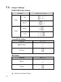
Jumper settings .......................................................................... 25
Appendix A: Drivers Installation..............31
Appendix B: OSD Functions for 2nd Display 32
Appendix C: VFD Customer Display .......35
- vi -
1
Item Checklist
Take the system unit out of the carton. Remove the unit from the carton by
holding it by the foam inserts. The following contents should be found in the
carton:
1-1
Standard Item
a.
b.
c.
d.
e.
a. System
b. Driver CD
c. RJ45-DB9 cable (x2)
d. Power cord
e. Power adapter
-1-
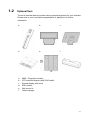
1-2
Optional Item
The touch terminal device provides various peripheral options for your selection.
Please refer to your local sales representative or distributor for further
information.
a.
b.
c.
d.
e.
f.
a.
b.
c.
d.
e.
f.
MSR + Fingerprint module
VFD customer display (with RJ45 cable)
Second display with touch
SSD module
Wall mount kit
Cable manager
-2-
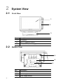
2
System View
2-1
Front View
1
2
3
2-2
No.
Description
1
AIO System
2
MSR + Fingerprint module
3
Stand (with the power supply)
Bottom View
4
5
6
-3-
No.
Description
4
Rubber foot
5
Power supply
6
Power supply bracket
2-3
Rear View
7
8
9
10
11
No.
2-4
Description
7
Speaker holes
8
VESA holes x4 (100x100mm)
9
Thumbscrew hole for stand / wall-mount bracket
10
HDD door
11
Cable manager
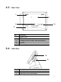
Side View
12
13
No.
Description
12
Ventilation holes
13
Stand hinge cover (at both sides)
-4-
2-5
I/O View
No.
Description
a
DC-IN (19V)
b
Parallel port
c
COM 1, 2, 3, 4(from left to right)
d
USB (x4)
e
Line-out
f
24V receipt printer power port
g
PS2
h
VGA
i
DVI (optional)
j
Power button switch
k
Wireless antenna mount (optional)
l
LAN
m
-5-
Mic-in (optional)
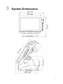
3
System Dimensions
-6-
4
Peripheral Installation
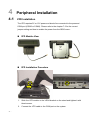
4-1
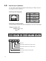
VFD Installation
The VFD requires 5V or 12V power and should be connected to the powered
COM port (COM3 or COM4). Please refer to the chapter 7-3 for the correct
jumper setting and how to enable the power from the BIOS menu..
VFD Module View
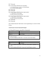
VFD Installation Procedure
1.
2.
-7-
Slide the VFD module to the VESA bracket on the stand and tighten it with
thumb screw.
Connect the VFD cable to the COM port on the system.
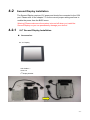
4-2
Second Display Installation
The Second Display requires 12V power and should be connected to the VGA
port. Please refer to the chapter 7-3 for the correct jumper setting and how to
enable the power from the BIOS menu.
Warning! Please make sure the system is turned off when you install the
Second Display as you can permanently damage your device!
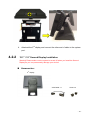
4-2-1
8.4" Second Display Installation
Accessories:
8.4” 2nd Display
VGA Cable x 1
Screw x 6
2nd Display Bracket
-8-
-9-
Installation Procedure:
1.
Attach the 2nd display bracket to the stand system and fasten the thumb
screw (x1)
2.
Attach the stand with 2nd display bracket to the LCD touch panel. Fix the
stand with 2nd display bracket on the VESA holes (x4) and fasten the
thumb screw (x1).
3.
Connect the VGA cable to the LCD touch panel.
4.
4-2-2
Attached the 2nd display and connect the other end of cable to the system
port.
12.1" / 15” Second Display Installation
Warning! Please make sure the system is turned off when you install the Second
Display as you can permanently damage your device!
Accessories:
2nd display
VGA Cable x 1
Screw x 2
- 10 -
Installation Procedure:
1.
2.
3.
- 11 -
Thread two ends of the cable respectively through the upper and the lower
gap on the 2nd display on the bracket.
Attach the 2nd display to the stand and fasten the screws (x2). Thread the
VGA cable through the hole at the bottom of the system.
Route the VGA cable through the stand gap of the system and connect the
other end of the VGA cable to the system port.
4-3
Power Cord Installation
The Power supply is
installed in the metal
bracket fixed in the stand
gap.
1.
2.
Connect the Power cord to the power supply.
Route through the base gap for cable management.
- 12 -
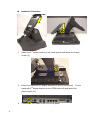
4-4
2-in-1 MSR Installation
1.
2.
3.
- 13 -
Loosen the screws (x2) on the MSR dummy cover.
Connect the respective connectors for 2-in-1 MSR module.
Fasten the screws (x2) to fix the MSR or 2-in-1 MSR module.
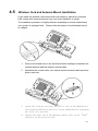
4-5
Wireless Card and Antenna Mount Installation
If you install the wireless LAN module after manufacturer, please buy wireless
LAN module with external antenna from your local distributor or dealer.
The installation procedure is slightly different depending on which motherboard
your system is equipped with. Please refer the location of motherboard layout
on chapter.
1.
2.
3.
4.
Press-out the blind hole on the enclosure before starting to assemble the
external antenna and the antenna coaxial cable.
Assemble the coaxial cable, nut, washer and the external cable as above
picture instructs.
Insert the wireless card into the mPCI-e slot on the motherboard.
Press down the WLAN card and fix it to the motherboard by fastening
the screw (x1) provided.
Connect the other end of the antenna coaxial cable to the “Main”
connector on the wireless card.
- 14 -
4-6
Cash Drawer Installation
You can install a cash drawer through the cash drawer port. Please verify the
pin assignment before installation.
Cash Drawer Pin Assignment
6
1
Pin
Signal
1
GND
2
DOUT bit0
3
DIN bit0
4
12V / 19V
5
DOUT bit1
6
GND
Cash Drawer Controller Register
The Cash Drawer Controller use one I/O addresses to control the Cash Drawer.
Register Location: 48Ch
Attribute: Read / Write
Size: 8bit
BIT
Attribute
7
X
6
5
BIT7 BIT6
Reserved
4
X X
3
2
1
BIT5
Read
BIT4
Reserved
BIT3 BIT2
Write
BIT1 BIT0
Reserved
0
X X
Reserved
Cash Drawer “DOUT bit0” pin output control
Cash Drawer “DOUT bit1” pin output control
Reserved
Cash Drawer “DIN bit0” pin input status
Reserved
- 15 -
Bit 7: Reserved
Bit 6: Cash Drawer “DIN bit0” pin input status.
= 1: the Cash Drawer closed or no Cash Drawer
= 0: the Cash Drawer opened
Bit 5: Reserved
Bit 4: Reserved
Bit 3: Cash Drawer “DOUT bit1” pin output control.
= 1: Opening the Cash Drawer
= 0: Allow close the Cash Drawer
Bit 2: Cash Drawer “DOUT bit0” pin output control.
= 1: Opening the Cash Drawer
= 0: Allow close the Cash Drawer
Bit 1: Reserved
Bit 0: Reserved
Note: Please follow the Cash Drawer control signal design to control the Cash
Drawer.
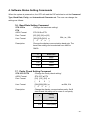
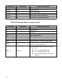
Cash Drawer Control Command Example
Use Debug.EXE program under DOS or Windows98
Command
Cash Drawer
O 48C 04
Opening
O 48C 00
Allow to close
Set the I/O address 48Ch bit2 =1 for opening Cash Drawer by “DOUT
bit0” pin control.
Set the I/O address 48Ch bit2 = 0 for allow close Cash Drawer.
Command
Cash Drawer
I 48C
Check status
The I/O address 48Ch bit6 =1 mean the Cash Drawer is opened or not
exist.
The I/O address 48Ch bit6 =0 mean the Cash Drawer is closed.
- 16 -
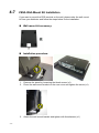
4-7
VESA Wall-Mount Kit Installation
If you want to mount the POS terminal on the wall, please order the wall mount
kit from you distributor and follow the steps below for the installation.
Wall-mount kit accessory:
Installation procedure:
- 17 -
1.
2.
Remove the stand by loosening the thumb screw (x1).
Place the wall mount bracket on the rear cover and tighten the screw (x1).
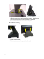
3.
Attach the wall mount bracket and tighten with thumbscrew (x1)
4-8
Stand Assembly & Disassembly
Stand Assembly
1.
2.
Slide the VESA hinge bracket into the metal hinge shaft on the stand.
Fasten the screws (x6) ( 3 on both sides) to fix the VESA hinge bracket
onto the stand.
3.
Use rubber hinge cover to plug the holes on both sides.
- 18 -
4.
5.
Align larger end of the teardrop mounting holes on the VESA hinge bracket
with fixing screws (x4) on the rear cover of the system. Slide to narrow
end of the mounting holes, and stick the bracket to the system.
Push and fasten the thumb screw to fix it to the system.
Stand Disassembly
1.
2.
- 19 -
Loosen the thumb screw.
Slide the system upward to separate from the stand.
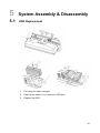
5
System Assembly & Disassembly
5-1
HDD Replacement
1.
2.
3.
Pull away the cable manager.
Remove the screw (x1) to open the HDD door.
Replace the HDD.
- 20 -
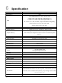
6
Specification
Model
Motherboard
Breeze Performance
C93
Intel Sandy Bridge CPU, LGA 1155-pin, 32nm
i7-2600 3.4G, L2 8M, TDP 95W, supports AMT 7.0
CPU
i5- 2400 3.1G, L2 6M, TDP 95W, supports AMT 7.0
i3 - 2120 3.3G, L2 3M, TDP 65W, supports standard manageability
G850 Pentium dual core 2.9G L2 3M, 65W
Celeron G530 2.4G L2 2M, 65W
Chipset
System Memory
Intel ® Q67 PCH (AMT, RAID 0,1 hot swap, PCI and PCI E, SATA II /III)
2 x DIMM socket up to 16GB DDR3 1066/1333 Mhz
Integrated in Q67 processor, frequency 850Mhz
Graphic Memory
Intel HD Graphics integrated in Q67 Processor with Shared System
Memory
LAN controller
Intel 82579LM Giga LAN 2nd LAN Intel WG82583
Audio controller
Realtek ALC 662-GR HD codec
I/O controller
BIOS
MB dimension
Winbond W83627UHG
AMI
270 x 174mm
LCD Display
LCD
Touch
15.1" , 250nits, 1024 *768 max resolution
15" Elo resistive touch
15" Projected capacitive touch
Storage
HDD
Flash memory
2.5" x2 HDD bay supports hot swap, Intel hardware RAID 0,1,
SSD Solid State Disk (option)
Rear I/O ports
USB
4 x USB (2.0 )
24V Receipt printer power port
1
2nd VGA
1
LAN (10/100/1000)
2
4 x RJ45 COM
Serial/COM
(COM1/COM2 standard RS-232 without power, COM3 /COM4 powered
COM with power enable /disable by BIOS, jumper setting default COM3
+12V and COM4 +5V)
Line out
- 21 -
1
MIC in
1 (option)
Parallel port
1
PS2
1
DVI
1 (option)
Power button
1
Front
Power LED indicator
Blue power LED
Power
Power Adapter
Ext. 19V / 180W
Speaker
2 x 2W speaker
Peripheral
POS peripherals
Customer Display
2nd display (optional Touch)
MSR (IDTECH, PS2 /USB ) / Finger Print Reader (USB)
MSR (Magetek encrypted MSR (USB)
2 x 20 VFD (COM)
8.4" /12.1" /15" 2nd display
Wireless Card (b/g/n)
1
Expansion
Mini-PCI-E Slot
1
Environment
Operating Temperature
Storage Temperature
5°C ~ 35°C ( 41°F ~ 95°F )
-20°C ~ 55°C (-4°F ~ 140°F)
Operating Humidity
20% - 80% RH non condensing
Storage Humidity
20% - 85% RH non condensing
Certificate
EMC & Safety
Dust & Water Proof
FCC Class A, CE, LVD
Front bezel
Others
Dimension (W x D x H)
OS Support
0°: W 362.38x D 279.38x H 269.74mm without MSR
60°: W 362.38x D 279.38x H 336.99mm without MSR
Windows XP professional, POS Ready 2009, XP Embedded, Linux,
Windows 7, POS Ready 7
* This specification is subject to change without prior notice.
- 22 -
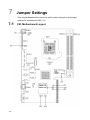
7
Jumper Settings
This chapter describes the connector with function description and jumper
settings for motherboard C93 V1.0.
7-1
- 23 -
C93 Motherboard Layout
7-2
Connector and function
Connectors
Functions
CN1
Power button connector
CN4
DVI connector
CN5/CN9
LAN1/2 LED(Internal)
CN6
SPI flash
CN7
Line out jack
CN8
MIC-in connector
FAN_CPU1
CPU FAN connector
FAN_SYS1
System FAN connector
PRN1
Parallel port
PS1
PS2 keyboard
PWR1
+19V DC jack
PWR4
+24V out DC jack
RJ45_1
COM1/ COM2/ COM3/ COM4
RJ45_2
RJ45 W/Transformer/LED/USBX2
RJ45_3
RJ45 W/Transformer/LED/USBX2
VGA1
VGA
SKT1
CPU socket
DDR3_A1
DDR3 LONG-DIMM channel A
DDR3_A1
DDR3 LONG-DIMM channel B
JP1
Power mode setting
JP2
COM3/4 power setting
JP3
CMOS operation mode
JP5
ME update
JP6
LCD ID setting
JP8
Inverter selection
JP9
System indicator
- 24 -
7-3
Jumper settings
COM3/COM4 Power Setting
Function
JP2 (1-2) (3-4) (5-6) (7-8)
+5V
COM3
▲+12V
▲+5V
COM4
+12V
Power Mode Setting
Function
JP1
(1-2)
JP5
(1-2)
▲ATX Power
AT Power
ME Update
Function
▲Lock
Unlock
▲ = Manufacturer Default Setting
- 25 -
Inverter Selection
Function
JP8
(1-2) (3-4) 5-6)
▲CCFL W/BN
LED W/BN
▲ = Manufacturer Default Setting
- 26 -
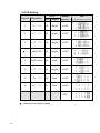
LCD ID Setting
LVDS
Output
Interface
Panel #
Resolution
1
800 x 600
18
Single
LVDS
3
800 x 600
24
Single
LVDS
5
1024 x 768
18
Single
LVDS
▲ 7
1024 x 768
24
Single
LVDS
9
1280 x 1024
24
Dual
LVDS
11
1366 x 768
24
Single
LVDS
13
1440 x 900
24
Dual
LVDS
15
1920 x 1020
24
Dual
LVDS
Bits Channel
CRT
▲ = Manufacturer Default Setting
- 27 -
JP6
(1-2) (3-4) (5-6) (7-8) (9-10)
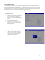
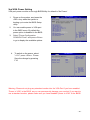
SATA RAID Setting
To set the RAID program, you must install two SATA HDD first. After the hardware has
been installed, please reboot the system. At system boot, press the <Ctrl> and <I> keys
simultaneously to run the Intel RAID Configuration Utility when prompted by the following
message: Press <Ctrl> <I> for the Intel RAID Configuration Utility.
BIOS/Utility setup
1. Power on the system, and press the
<DEL> key when the system is
booting up to enter the BIOS Setup
utility.
2. Select the Advanced tab
3. Select "SATA Configuration" and
press <Enter> to go to display the
available options.
4.
Select "SATA Mode" and press
<Enter>. Select “RAID Mode” and
press <Enter>. Please Save the
change by pressing F10
- 28 -
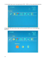
COM3 & COM4 Power Setting
COM3 and COM4 can be set to provide power to your serial device.
The voltage can be set to +5V or 12V by setting jumper JP2 on the motherboard.
When enabled, the power is available on pin 10 of the RJ45 serial connector.
If you use the serial RJ45 to DB9 adapter cable, the power is on pin 9 of the DB9 connector.
By default, the power option is disabled in the BIOS.
Warning: Please do not plug non-powered peripheral devices (e.g. printers, scanners etc)
into the powered COM ports- as you can permanently damage your device!
Enable COM3/COM4 power in BIOS
1. Power on the system, and
press the <DEL> key when the
system is booting up to enter
the BIOS Setup utility.
2. Select the Advanced tab
3. Select Power Configuration
COM/VGA Ports and press
<Enter> to go to display the
available options.
4. To enable the power, select
COM3 Power Setting or
COM4 Power setting and
press <Enter>. Select Power
and press <Enter>.
Save the change by pressing
F10.
- 29 -
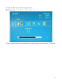
2nd VGA Power Setting
VGA port power must be on through BIOS/Utility for default is “No Power“
1.
2.
3.
4.
Power on the system, and press the
<DEL> key when the system is
booting up to enter the BIOS Setup
utility.
You can enable power to VGA port
in the BIOS menu. By default the
power option is disabled in the BIOS.
Select "Power Configuration
COM/VGA Ports" and press <Enter>
to go to display the available options.
To switch on the power, select
"+12V" press <Enter>. Please
Save the change by pressing
F10
Warning: Please do not plug any standard monitor into the VGA Port if you have enabled
“Power to VGA” in the BIOS, as you can permanently damage your monitor! If you want to
use a standard monitor, please make sure you have disabled "power to VGA" in the BIOS!
- 30 -
Appendix A: Drivers Installation
The shipping package includes a Driver CD in which you can find every
individual driver and utility that enables you to install the drivers on the system.
Please insert the Driver CD into the drive and double click on the “index.htm” to
select the models. You can refer to the drivers installation guide for each driver
in the “Driver/Manual List”.
- 31 -
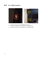
Appendix B: OSD Functions for 2nd Display
Condition
SW1
SW2
SW1+SW2
Normal Mode
(Signal Input Mode)
Power
Auto Tune
Menu Mode
(SW1 + SW2 keep press 3 seconds)
Menu Mode
Right
Select
No Function
PS: 2 Key OSD only shifts to right when press SW1 key in menu mode.
(Ex: Brightness Value: 1→10→1)
- 32 -
1. In the signal input mode, keep pressing the SW1 + SW2 key 3 seconds at the same time.
2. Press the SW1 key to select video icon then press the SW2 key to enter brightness
adjustment.
- 33 -
3. Press the SW1 key to adjust brightness value.
(Brightness value: 1→2→3→4……..10→1→2…..)
4. Menu mode window will automatically close when there is no command for 10 seconds.
- 34 -
Appendix C: VFD Customer Display
1. Specification
NO
Item
1
Display method
2
Number of character
Description
Vacuum fluorescent display
40 characters
(20 columns x 2 lines)
3
Character font
5 x 7 Dot matrix
4
Display color
Blue green
5
Brightness
700 cd /m2
96 alphanumeric
6
Character type
25 kinds of international character set
1 user define character
7
Character size
8
Power supply
9.0mm x 5.25mm
12 ~ 24VDC
Manufacture offer +12V power adapter
9
Power consumption
3~6W
10 MTBF
25000 hours (power on time)
11 Panel dimensions
224 (W) x 93 (H) x 50(D) mm
Long support : 22 cm
12 Support dimensions
Short support : 9 cm
- 35 -
13 Base dimensions
190(w)x55(h)x96(d)mm
14 Viewing angle
-5 ~ 60 degrees
15 Rotation angle
Maximum 270 degrees
16 Weight
1.25 Kg
17 Operating temperature 5 ~ 45oC
18 Operating Humidity
30% ~ 85%
19 Storage Temperature
-10 ~ 55 oC
20 Storage Humidity
10% ~ 85%
- 36 -
2. Interface
Data transmission
Serial
Synchronization
Asynchronous
Signal level
MARK = -3 to –15 V (logic “1”)
SPACE = +3 to +15 V (logic “0”)
Baud rates
4800, 9600, 19200, 38400 bps
Parity
None, even
Bit length
8 bits
Stop bits
1 bit
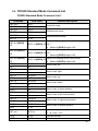
3. Dip Switch and Software Setting
1.1. Command Type Selection
SW1
SW2
SW3
Command Type
Demo Mode Support
ON
ON
ON
PS7300
No
OFF
ON
ON
EPSON ESC/POS
Yes
ON
OFF
ON
ADM 787/ ADM 788
No
OFF
OFF
ON
DSP800
Yes
ON
ON
OFF
AEDEX/ EMAX
No
OFF
ON
OFF
UTC/P
No
ON
OFF
OFF
UTC/S
No
OFF
OFF
OFF
CD5220
Yes
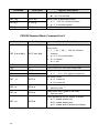
1.2. Baud Rate Selection
SW8
SW9
Baud Rate (bps)
ON
ON
4800
OFF
ON
9600
ON
OFF
19200
OFF
OFF
38400
Default
*
1.3. Parity Check Selection
- 37 -
SW10
Parity Check
Default
ON
None-parity
*
OFF
Even-parity
Default
*
1.4. Command Control
SW12
Function
ON
Depends on SW1~SW11 setting
OFF
Bypass SW1~SW11 setting, fixed at:
Command type: POS7300,
Baud rate: 9600
Parity check: None-parity
Demo mode: Disable
- 38 -
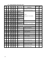
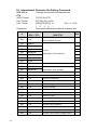
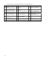
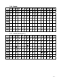
1.5. International Character Set
SW
SW
SW
SW
SW
Character Set
Code Table
4
5
6
7
11
(20h – 7Fh)
(80H-FFH)
0
ON
ON
ON
ON OFF U.S.A.
1
OFF ON
ON
ON OFF FRANCE
2
ON OFF ON
ON OFF GERMANY
3
OFF OFF ON
ON OFF U.K.
4
ON
5
OFF ON OFF ON OFF SWEDEN
6
ON OFF OFF ON OFF ITALY
7
OFF OFF OFF ON OFF SPAIN
8
ON
9
OFF ON
10
ON OFF ON OFF OFF DENMARK II
ID
ON OFF ON OFF DENMARK I
ON
CP-437
(USA, Standard Europe)
CP-858
(Multilingual + Euro Symbol)
ON OFF OFF JAPAN
Katakana
ON OFF OFF NORWAY
CP-858
(Multilingual + Euro Symbol)
11 OFF OFF ON OFF OFF Slawie
12
ON
ON OFF OFF OFF RUSSIA
13 OFF ON OFF OFF OFF U.S.A.
CP-860 (Portuguese)
14
Greek
ON OFF OFF OFF OFF U.K.
15 OFF OFF OFF OFF OFF U.S.A.
CP-852 (Hungary)
16
ON
ON
ON
ON U.S.A.
CP-862 (Hebrew)
17 OFF ON
ON
ON
ON U.S.A.
CP-863 (Canadian-French)
ON OFF ON
ON
ON U.S.A.
CP-865 (Nordic)
19 OFF OFF ON
ON
ON U.S.A.
CP-866 (Cyrillic)
ON OFF ON
ON U.S.A.
Windows-1251 (Cyrillic)
21 OFF ON OFF ON
ON U.S.A.
22
ON OFF OFF ON
ON U.S.A.
Windows-1255 (Hebrew)
23 OFF OFF OFF ON
ON U.S.A.
Windows-1257 (Baltic)
ON
ON OFF ON U.S.A.
Windows-1253 (Greek)
25 OFF ON
ON OFF ON U.S.A.
18
20
24
- 39 -
ON
ON
ON
Windows-1252
(West European Latin)
Windows-1250
(East European Latin)
Default
*
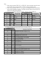
Note
4. Software Status Setting Commands
When the system is powered on, the VFD will read the DIP switches to set the Command
Type, Baud Rate, Parity, and International Character set. The user can change the
settings as follows:
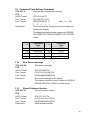
1.6. Baud Rate Setting Command
STX 05 B n
ETX
ASCII Format
Dec. Format
Hex. Format
Description
/Change the baud rate setting/
STX 05 B n ETX
[02] [05] [66] n [03]
30h≦n≦33h
[02h][05h][42h] n
[
0
3
h
]
Change the display communication baud rate. The
baud rate setting can be selected from 4800 to
38400.
n
Baud rate
30h
4800
31h
9600
32h
19200
33h
38400
1.7. Parity Check Setting Command
STX 05 P n ETX
ASCII Format
Dec. Format
Hex. Format
Description
/Change the Parity check setting/
STX 05 P n ETX
[02] [05] [80] n
[
0
3
]
[02h][05h][50h] n
n=30h, 31h
[ 0 3 h ]
Change the display communication parity. Set 8
data bit and the parity set for even or non-parity.
n
Parity
check
30h
None-parity
31h
Even-parity
- 40 -
1.8. International Character Set Setting Command
STX 05 S n
ETX
ASCII Format
Dec. Format
Hex. Format
Description
n
- 41 -
/Change the international character set/
STX 05 S n ETX
[02] [05] [83] n [03]
30h≦ n ≦4Fh
[02h][05h][53h] n
[
0
3
h
]
Change the display international character font.
Character Set
(20h – 7Fh)
Code Table
(80H-FFH)
CP-437
30h
U.S.A.
31h
FRANCE
32h
GERMANY
33h
U.K.
34h
DENMARK I
35h
SWEDEN
36h
ITALY
37h
SPAIN
38h
JAPAN
Katakana
39h
NORWAY
CP-858
3Ah
DENMARK II
(Multilingual+ Euro Symbol)
3Bh
Slawie
3Ch
RUSSIA
3Dh
U.S.A.
CP-860 (Portuguese)
3Eh
U.K.
Greek
3Fh
U.S.A.
CP-852 (Hungary)
40h
U.S.A.
CP-862 (Hebrew)
41h
U.S.A.
CP-863 (Canadian-French)
42h
U.S.A.
CP-865 (Nordic)
43h
U.S.A.
CP-866 (Cyrillic)
44h
U.S.A.
Windows-1251 (Cyrillic)
45h
U.S.A.
Windows-1252 (West European Latin)
46h
U.S.A.
Windows-1255 (Hebrew)
47h
U.S.A.
Windows-1257 (Baltic)
48h
U.S.A.
Windows-1253 (Greek)
49h
U.S.A.
Windows-1250 (East European Latin)
(USA, Standard Europe)
CP-858
(Multilingual + Euro Symbol)
Note
1.9. Command Type Setting Command
STX 05 C n
ETX
ASCII Format
Dec. Format
Hex. Format
Description
1.10.
STX 05 C n ETX
[02] [05] [67] n [03]
30h≦ n ≦37h
[02h][05h][43h] n
[
0
3
h
]
This command will change the command type and
initialize the display.
The display emulation mode is based on DSP800/
ESC/ ADM 787/ POS7300/ AEDEX/ UTC/ CD5220
mode.
n
Command
Type
n
Command
Type
30h
POS7300
34h
AEDEX
31h
ESC/POS
35h
UTC/P
32h
ADM 787
36h
UTC/S
33h
DSP800
37h
CD5220
Run Demo message
STX 05 D 08
ETX
ASCII Format
Dec. Format
Hex. Format
Description
1.11.
/Change the command type setting/
/Run demo message/
STX 05 D 08 ETX
[02][05][68][08][03]
[02h][05h][44h][08h][03h]
Run demo message for the display.
The display emulation mode is based on DSP800,
EPSON ESC/POS, CD5220 command type.
Show Firmware Version
STX 05 V 01
ETX
ASCII Format
Dec. Format
/Show Firmware Version/
Hex. Format
Description
[02h][05h][56h][01h][03h]
Show firmware version.
STX 05 V 01 ETX
[02][05][86][01][03]
- 42 -
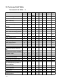
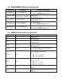
5. Command List Table
Command List Table – 1
POS7300 CD5220
EPSON
D101
UTC/S UTC/P AEDEX ADM788 DSP800
Move cursor right
O
O
O
Move cursor left
O
O
O
Move cursor up
O
O
O
Move cursor down
O
O
O
O
O
O
Move cursor to left-most position
O
O
O
Move cursor to home position
O
O
O
O
O
O
O
O
Clear display screen
O
O
O
Clear cursor line
O
O
O
O
O
O
Move cursor to right-most
position
Move cursor to bottom position
Move cursor to specified
position
Brightness adjustment
O
O
O
Blink display screen
O
O
O
O
Initialize display
O
O
O
O
O
O
O
O
Select character code table
Select international character
set
Select/cancel reverse character
O
O
Overwrite mode
O
O
O
O
Vertical scroll mode
O
O
O
O
Horizontal scroll mode
O
O
O
Set/cancel the window range
O
O
Select peripheral device
O
O
Set starting/ending position of
O
macro definition
Execute and quit macro
Execute self-test
O
O
O
Display time
O
Display time continuously
O
Display position
- 43 -
O
O
O
O
O
POS7300 CD5220
Cursor on/off
O
O
EPSON
D101
O
Change to UTC enhanced mode
UTC/S UTC/P AEDEX ADM788 DSP800
O
O
Change to UTC standard mode
Write string to upper line
O
O
O
O
O
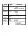
Command List Table – 2
POS7300 CD5220
Upper line message continuous
scroll
Bottom line message scroll
continuously
Message vertical down scroll
continuously
Message vertical upper scroll
continuously
O
EPSON
D101
UTC/S UTC/P AEDEX ADM788 DSP800
O
O
O
O
O
O
Carriage return
O
O
Line feed
O
O
Back space
O
O
Horizontal tab
O
O
Command type select
O
Upper line message scroll once
O
O
O
O
O
Change attention code
O
O
Two line display
O
O
pass
Clear upper line and move
O
cursor to upper left-end position
Clear bottom line and move
cursor to bottom left-end
O
position
Set period to upper line, last n
O
position
Set line blinking, upper line
O
O
Clear line blinking, upper line
O
O
- 44 -
POS7300 CD5220
EPSON
D101
Clear field 1 and move cursor to
UTC/S UTC/P AEDEX ADM788 DSP800
O
field 1, first position
Clear field 2 and move cursor to
O
field 2,first position
Clear display range from n
position to m position and move
O
cursor to n position
Save the current displaying data
O
to n layer for demo display
Turn annunciator on/off
O
Specify period
O
Specify comma
O
Specify semicolon (period +
comma)
- 45 -
O
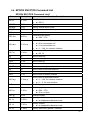
6. Command Details
6.1. POS7300 Series Command List
POS7300 Standard Mode Command List-1
Command
Code (hex)
Function Description
ESC F A [DATA]
1B 46 41 [DATA] 0D
CR
Write string to upper line
ESC F B [DATA]
1B 46 42 [DATA] 0D
CR
Write string to lower line
ESC F D [DATA]
1B 46 44 [DATA] 0D
CR
Upper line message scroll continuously
ESC F O [DATA]
1B 46 4F [DATA] 0D
CR
Bottom line message scroll continuously
Maximal [DATA] length is 40
Maximal [DATA] length is 40
Maximal [DATA] length is 40
Maximal [DATA] length is 40
Move cursor to specified position
ESC P x y
1B 50 x y
ESC _ n
1B 5F n
ESC DC1
1B 11
Overwrite mode
ESC DC2
1B 12
Vertical scroll mode
ESC DC3
1B 13
Horizontal scroll mode
ESC @
1B 40
Initialize display
US MD1 n
1F 01 n
US MD2 n
1F 02 n
x = 1 ~ 14h, for columns location.
y = 1 ~ 2, for lines location.
Set cursor on/off
n = 00 ~ 01
Message vertical upper scroll continuously
n = 01 ~ 0Ch
Message vertical down scroll continuously
n = 01 ~ 0Ch
Set line blinking
US DC1 n
1F 11 n
n = ’1’ ~ ’2’
n = ’1’ up line
n = ’2’ low line
Clear line blinking
US DC2 n
1F 12 n
n = ’1’ ~ ’2’
n = ’1’ up line
n = ’2’ low line
Blink display screen
US E n
1F 45 n
n = 00h ~ FFh
n = 0 for no blink
- 46 -
Command
Code (hex)
Function Description
NULL H
0 48
Move cursor up
NULL K
0 4B
Move cursor left
NULL M
0 4D
Move cursor right
NULL P
0 50
Move cursor down
NULL G
0 47
Move cursor to left-most position
NULL O
0 4F
Move cursor to right-most position
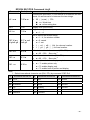
POS7300 Standard Mode Command List-2
Command
Code (hex)
Function Description
BS
08
Back space
HT
09
Horizontal tab
LF
0A
Line feed
HOM
0B
Move cursor to home position
CLR
0C
Clear display screen
CLR
12
Clear display screen
CR
0D
Carriage return
CAN
18
Clear cursor line, and clear string mode
DLE n
10 n
Display position
n = 0 ~ 27h, for location.
Select peripheral device, display or printer
ESC = n
- 47 -
1B 3D n
n = 1~3
n = '1': enable printer only
n = '2': enable display only
n = '3': enable both of printer and
display
6.2. CD5220 Standard Mode Command List
CD5220 Standard Mode Command List-1
Command
Code (hex)
ESC DC1
1B 11
US SOH
1F 01
ESC DC2
1B 12
US STX
1F 02
ESC DC3
1B 13
US ETX
1F 03
ESC Q A [DATA]
CR
ESC Q B [DATA]
CR
Function Description
Overwrite mode
Vertical scroll mode
Horizontal scroll mode
Set the string display mode, write string to upper
1B 51 41 [DATA] 0D line. *1
Maximal [DATA] length is 20
Set the string display mode, write string to lower
1B 51 42 [DATA] 0D line. *1
Maximal [DATA] length is 20
Upper line message scroll continuously. *1 *2
ESC Q D [DATA]
CR
1B 51 44 [DATA] 0D
ESD [ D
1B 5B 44
BS
08
ESC [ C
1B 5B 43
HT
09
ESC [ A
1B 5B 41
US LF
1F 0A
ESC [ B
1B 5B 42
LF
0A
ESC [ H
1B 5B 48
HOM
0B
ESC [ L
1B 5B 4C
CR
0D
ESC [ R
1B 5B 52
US CR
1F 0D
ESC [ K
1B 5B 4B
US B
1F 42
ESC # n
1B 23 n
US @
1F 40
Execute self test
US E n
1F 45 n
Blink display screen
Maximal [DATA] length is 40
Move cursor left
Move cursor right
Move cursor up
Move cursor down
Move cursor to home position
Move cursor to left-most position
Move cursor to right-most position
Move cursor to bottom position
Command type select
n = 30h ~ 37h
- 48 -
Command
Code (hex)
Function Description
n = 00h ~ FFh
n = 0 for no blink
ESC I x y
1B 6C x y
Move cursor to specified position
US $ x y
1F 24 x y
ESC @
1B 40
Initialize display
x = 1 ~ 14h, for columns location.
y = 1,2, for lines location.
CD5220 Standard Mode Command List-2
Command
Code (hex)
Function Description
Set or cancel the window range at horizontal
scroll mode
1 ≦ x1 ≦ x2 ≦ 14h, for columns
ESC W s x1 x2 y
location.
1B 57 s x1 x2 y
y = 1~2, for lines location.
s = 0: cancel
s = 1: set
CLR
0C
Clear display screen, and clear string mode
CAN
18
Clear cursor line, and clear string mode
ESC * n
1B 2A n
US X n
1F 58 n
Brightness adjustment
n = 1 ~ 4, n = 4 for highest brightness
Set cursor on/off
ESC _ n
1B 5F n
ESC f n
1B 66 n
ESC c n
1B 63 n
n = 1: cursor on
n = 0: cursor off
Select international fonts
About n, refer. *3
Select fonts, ASCII code or JIS code,
About n, refer. *4
Select peripheral device, display or printer
ESC = n
- 49 -
1B 3D n
n='1': enable printer only
n='2': enable display only
n='3': enable both of printer and display
Note:
1. While using command “ESC Q A” or “ESC Q B”, other commands cannot be used
except when using command “CLR” or “CAN” to change operating mode.
2. When using command “ESC Q D”, the upper line message will scroll continuously
until a new command is received, it will then clear the upper line and move the
cursor to the upper left-end position.
3. Select the international Character set (20h – 7Fh) by command “ESC f n”.
Parameter “n”
Character
Hex
‘A’
41h
‘G’
International
Character Set
Parameter “n”
International
Character Set
Character
Hex
U.S.A.
‘W’
57h
Sweden
47h
Germany
‘D’
44h
Denmark I
’I’
49h
Italy
‘E’
45h
Denmark II
‘J’
4Ah
Japan
‘L’
4Ch
Slavonic
‘U’
55h
U.K.
‘R’
52h
Russia
‘F’
46h
France
‘S’
53h
Spain
‘N’
4Eh
Norway
4. Select character code table (80H-FFH) by command “ESC c n”.
Parameter “n”
character Code Table
Character
Hex
‘A’
41h
Compliance with ASCII code (CP-437)
‘J’
4Ah
Compliance with JIS code (Katakana)
‘L’
4Ch
Compliance with Slawie code
‘R’
52h
Compliance with RUSSIA code
‘M’
4Dh
CP-850 (Multilingual)
‘P’
50h
CP-858 (Multilingual+ Euro Symbol)
‘p’
70h
CP-860 (Portuguese)
‘F’
46h
CP-863 (Canadian-French)
‘N’
4Eh
CP-865 (Nordic)
‘u’
75h
CP-852 (Hungary)
‘H’
48h
CP-862 (Hebrew)
‘C’
43h
CP-866 (Cyrillic)
‘G’
47h
Greek
‘c’
63h
Windows-1251 (Cyrillic)
‘W’
57h
Windows-1252 (West European Latin)
‘h’
68h
Windows-1255 (Hebrew)
‘B’
42h
Windows-1257 (Baltic)
‘g’
67h
Windows-1253 (Greek)
- 50 -
Parameter “n”
Character
Hex
‘E’
45h
character Code Table
Windows-1250 (East European Latin)
6.3. UTC Standard Mode Command List
Command
Code (hex)
Function Description
BS
08
Back space
HT
09
Horizontal tab
LF
0A
Line feed
CR
0D
Carriage return
DLE n
10 n
DC1
11
Over write display mode
DC2
12
Vertical scroll mode
DC3
13
Cursor on
DC4
14
Cursor off
US
1F
Clear display
ESC d
1B 64
Change to UTC enhanced mode
Display position
n = 0 ~ 27h, for location.
6.4. UTC Enhanced Mode Command List
Command
Code (hex)
Function Description
ESC u A [DATA]
1B 75 41 [DATA] 0D
CR
Upper line display
ESC u B [DATA]
1B 75 42 [DATA] 0D
CR
Bottom line display
ESC u D [DATA]
1B 75 44 [DATA] 0D
CR
Upper line message scroll continuously
ESC u E h h : m
1B 75 45 h h ':' m m 0D
m CR
Display time
ESC u F [DATA]
1B 75 46 [DATA] 0D
CR
Upper line message scroll Once pass
Maximal [DATA] length is 20
Maximal [DATA] length is 20
Maximal [DATA] length is 40
h, m = '0' ~ '9'
Maximal [DATA] length is 40
Change attention code
ESC u H n m CR 1B 75 48 n m 0D
ESC u I [DATA]
CR
1B 75 49 [DATA] 0D
Two line display
ESC RS CR
1B 0F 0D
- 51 -
n = 1 ~ 20h
m = 1 ~ 20h
Maximal [DATA] length is 40
Change to UTC standard mode
6.5. AEDEX/EMAX Mode Command List
Command
Code (hex)
! # 4 [DATA] CR 21 23 34 [DATA] 0D
!#5hh:mm
21 23 35 h h ':' m m 0D
CR
! # 8 n m CR
21 23 38 n m 0D
! # 9 [DATA] CR 21 23 39 [DATA] 0D
! # 6 [DATA] CR 21 23 36 [DATA] 0D
Function Description
Upper line message scroll
Maximal [DATA] length is 40
Display time
h, m = '0' ~ '9'
Change attention code
n, m = 1 ~ 20
Two line display
Maximal [DATA] length is 40
Upper line message scroll once pass
Maximal [DATA] length is 40
6.6. ADM787/788 mode command list
Command
Code (hex)
Function Description
CLR
0C
Clear display
CR
0D
Carriage return
SLE1
0E
Clear upper line and move cursor to upper
left-end position
SLE2
0F
Clear bottom line and move, Cursor to bottom
left-end position
DC0 n
10 n
Set period to upper line last n position
n = 31H ~ 37H
Set line blinking, upper line
DC1 n
11 n
n = '1' ~ '2'
n = '1': up line
n = '2': low line
Clear line blinking, upper line
n = '1' ~ '2'
n = '1': up line
n = '2': low line
DC2 n
12 n
SF1
1E
Clear field 1 and move cursor to field 1, first
position
SF2
1F
Clear field 2 and move cursor to field 2, first
position
- 52 -
6.7. DSP800 Mode Command List
Command
Code (hex)
EOT SOH I n ETB
04 01 49 n 17
EOT SOH P n ETB
04 01 50 n 17
EOT SOH C n m
ETB
EOT SOH S n ETB
04 01 43 n m 17
Function Description
Select international character set
Move cursor to specified position
n = 31h ~ 58h
Clear display range from n position to m
position and move cursor to n position
04 01 53 n 17
n = 00 ~ 0Fh or 30 ~ 3Fh
31h ≦ n ≦ m ≦ 58h
Save current view message to n layer for
demo view data
n = 31h ~ 35h
Display the saved demo message
EOT SOH D n m ETB 04 01 44 n m 17
n = 31h ~ 4Fh
m = 31h ~ 33h
EOT SOH A n ETB
04 01 41 n 17
n =31h-34h
EOT SOH F n ETB
04 01 46 n 17
00h≦n≦FFh
EOT SOH # n ETB
04 01 23 n 17
n =30~37h
Command type select
EOT SOH % ETB
04 01 25 17
Initialize display
EOT SOH @ ETB
04 01 40 17
Execute self-test
Brightness adjustment
Blink display Screen
n = 00h ~ FFh, n = 0 for no blink
Select peripheral device, display or printer
EOT SOH = n ETB
- 53 -
04 01 3D n 17
n = '1': enable printer only
n = '2': enable display only
n = '3': enable both of printer and display
6.8. EPSON ESC/POS Command List
EPSON ESC/POS Command List-1
Command
Code (hex)
Function Description
Select/cancel reverse character.
US r n
1F 72 n
US MD1
1F 01
Specify overwrite mode.
US MD2
1F 02
Specify vertical scroll mode.
US MD3
1F 03
Specify horizontal scroll mode.
CAN
18
Clear cursor line
ESC # n
1B 23 n
n = 00,01
Command type select
n = 30h ~ 37h
Turn annunciator on/off.
US # n x
1F 23 n x
n = 0 for annunciator off
n = 1 for annunciator on
x = 1 ~ 14h, for columns location.
Set cursor on/off
US C n
1F 43 n
BS
08
Move cursor left
HT
09
Move cursor right
US LF
1F 0A
Move cursor up
LF
0A
Move cursor down
US CR
1F 0D
Move cursor to right-most position
CR
0D
Move cursor to left-most position
HOM
0B
Move cursor to home position
US B
1F 42
Move cursor to bottom position
n = 00, 01
Move cursor to specified position
US $ x y
1F 24 x y
x = 1 ~ 14h, for columns location.
y = 1 ~ 2, for lines location.
CLR
0C
Clear display screen
Blink display screen
US E n
1F 45 n
n = 00h ~ FFh
n = 0 for no blink
ESC @
1B 40
Initialize display
US . n
1F 2E n
US , n
1F 2C n
US ; n
1F 3B n
Specify period
n = a displayable character code
Specify comma
n = a displayable character code
Specify semicolon (period + comma)
- 54 -
Command
Code (hex)
Function Description
n = a displayable character code
US :
1F 3A
Set starting/ending position of macro definition.
Ex.: 1F 3A … (macro string) … 1F 3A
US @
1F 40
Execute self - test
1F 54 h m
Display time
0 ≦ h ≦ 17h, for hours setting.
0 ≦ m ≦ 3Bh, for minutes setting.
US T h m
- 55 -
EPSON ESC/POS Command List-2
Command
US ^ n m
Code (hex)
1F 5E n m
Function Description
Execute and quit macro. It’s an interval of n between the two
words. It’s an interval of m between the two strings.
00 ≦ (n, m) ≦ FFh
n = Word time
m = show string time
US U
1F 55
Display time continuously
US X n
1F 58 n
Brightness adjustment
n=1~ 4
Set or cancel the window range
ESC W n s
1B 57 n s x1
x1 y1 x2 y2
y1 x2 y2
n = 1 ~ 4, for window number
s = 0: cancel
s = 1: set
1 ≦ x1 ≦ x2 ≦ 14h, for columns location.
1 ≦ y1 ≦ y2 ≦ 2, for lines location.
ESC R n
1B 52 n
ESC t n
1B 74 n
Select international character set (20H~7Fh).
n = 00 ~ 0Fh. See note *1
Select character code table (80H~FFh).
n = 00 ~ 1Fh. See note *2
Select peripheral device, display or printer
ESC = n
1B 3D n
n = '1': enable printer only
n = '2': enable display only
n = '3': enable both of printer and display
Note:
1. Select international character set (20H~7Fh) by command “ESC R n”
n
International character set
n
International character set
n
International character set
0h U.S.A.
6h ITALY
Ch RUSSIA
1h FRANCE
7h SPAIN
Dh Not used
2h GERMANY
8h JAPAN
Eh Not used
3h U.K.
9h NORWAY
Fh Not used
4h DENMARK I
Ah DENMARK II
5h SWEDEN
Bh SLAVONIC
- 56 -
2. Select character code table (80H~FFh) by command “ESC t n”
n
Character code table
CP-437
n
Character code table
n
Character code table
7h Russia
Fh Windows-1257 (Baltic)
1h Katakana (for Japan)
8h Greek
10h
2h CP-850 (Multilingual)
9h CP-852 (Hungary)
11h Windows-1253 (Greek)
3h CP-860 (Portuguese)
Ah CP-862 (Hebrew)
12h
Bh CP-866 (Cyrillic)
13h
0h
4h
(USA, Standard Europe)
CP-863
(Canadian-French)
5h CP-865 (Nordic)
Ch Windows-1251 (Cyrillic)
6h Slawie
Eh Windows-1255 (Hebrew)
- 57 -
Windows-1252
(West European Latin)
Windows-1250
(East European Latin)
CP-858 (Multilingual+ Euro
Symbol)
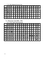
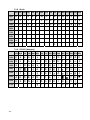
7. Character Set
7.1. Character Code 20H – 7FH
7.1.1. International Character Sets
Character Code Number
Hex
23
24
40
5B
5C
5D
5E
60
7B
7C
7D
7E
Dec
35
36
64
91
92
93
94
96
123
124
125
126
U.S.A
#
$
@
[
\
]
^
`
{
¦
}
~
France
#
$
à
°
ç
§
^
`
é
ù
è
¨
Germany
#
$
§
Ä
Ö
Ü
^
`
ä
ö
ü
β
U.K
£
$
@
[
\
]
^
`
{
¦
}
~
Denmark I
#
$
@ Æ
Ø
Å
^
`
æ
ø
å
~
Sweden
#
¤
É
Ä
Ö
Å
Ü
é
ä
ö
å
ü
Italy
#
$
@
°
\
é
^
ù
à
ò
è
ì
Spain
Pt
$
@
¡
Ñ
¿
^
`
¨
ñ
}
~
Japan
#
$
@
[
¥
]
^
`
{
¦
}
~
Norway
#
¤
É
Æ
Ø
Å
Ü
é
æ
ø
å
ü
Denmark II
#
$
É
Æ
Ø
Å
Ü
é
æ
ø
å
ü
Slavonic
#
$
@
[
\
]
^
`
{
¦
}
~
Russia
#
$
@
[
\
]
^
`
{
¦
}
~
Country
- 58 -
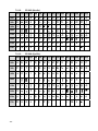
7.1.2. USA, Standard Character Sets
00h 01h 02h 03h 04h 05h 06h 07h 08h 09h 0Ah 0Bh 0Ch 0Dh 0Eh 0Fh
20h
30h
0
!
“
#
$ % &
‘
(
)
*
+
,
-
.
/
1
2
3
4
7
8
9
:
;
<
=
>
?
F G H
I
J
K
L
M
N
O
5
B C D E
6
40h
@ A
50h
P
Q R S
T
U V W X
Y
Z
[
\
]
^
_
60h
`
a
b
c
d
e
f
g
h
i
j
k
l
m
n
o
70h
p
q
r
s
t
u
v
w
x
y
Z
{
¦
}
~
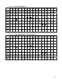
7.2. Character Code 80H – FFH
7.2.1. CP-437 (USA, Standard Europe)
00h 01h 02h 03h 04h 05h 06h 07h 08h 09h 0Ah 0Bh 0Ch 0Dh 0Eh 0Fh
80h
Ç
â
ä
à
å
ç
ê
ë
è
ï
î
ì
Ä
Å
90h
É æ Æ ô
ö
ò
û
ù
ÿ
Ö
Ü
¢
£
¥
Pt
ƒ
A0h
á
ó
ú
ñ
Ñ
ª
º
¿
⌐
¬
½ ¼
¡
«
»
B0h
░ ▒ ▓
│
┤ ╡ ╢ ╖ ╕ ╣
║
╗
╝
╜
╛
┐
C0h
└ ┴ ┬ ├ ─ ┼ ╞ ╟ ╚ ╔
╩
╦
╠
═
╬
╧
D0h
╨ ╤ ╥ ╙ ╘ ╒ ╓ ╫ ╪ ┘
┌
█
▄
▌
▐
▀
E0h
α
ß
Γ
π
Σ
σ
μ
τ
Φ
θ
Ω
δ
∞
ø
ε
∩
F0h
≡
±
≥
≤
⌠
⌡
÷
≈
°
•
·
√
n
²
■
- 59 -
ü
í
é
7.2.2. CP-850 (Multilingual)
00h 01h 02h 03h 04h 05h 06h 07h 08h 09h 0Ah 0Bh 0Ch 0Dh 0Eh 0Fh
80h
Ç
â
ä
à
å
ç
ê
ë
è
ï
î
ì
Ä
Å
90h
É æ Æ ô
ö
ò
û
ù
ÿ
ö
Ü
ø
£
Ø
×
ƒ
A0h
á
ó
ú
ñ
Ñ
a
o
¿
®
¬
½ ¼
¡
«
»
B0h
░ ▒ ▓
│
┤
Á
Â
À © ╣
║
╗
╝
¢
¥
┐
C0h
└ ┴ ┬ ├ ─ ┼
ã
Ã
╚ ╔
╩
╦
╠
═
╬
¤
D0h
ð
Đ
Ê
Ë
È
l
Í
Î
Ï
┘ 「 █
▄
¦
Ì
▀
E0h
ó
ß
ô
ò
õ
Õ
μ
þ
Þ Ú
Û
Ù
ý
Ý
¯
´
F0h
¯
±
= ¾
¶
§
÷
,
ü
˚
˙
1
3
2
■
í
é
¨
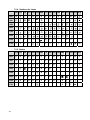
7.2.3. CP-858 (Multilingual + Euro Symbol)
00h 01h 02h 03h 04h 05h 06h 07h 08h 09h 0Ah 0Bh 0Ch 0Dh 0Eh 0Fh
80h
Ç
â
ä
à
å
ç
ê
ë
è
ï
î
ì
Ä
Å
90h
É æ Æ ô
ö
ò
û
ù
ÿ
ö
Ü
ø
£
Ø
×
ƒ
A0h
á
ó
ú
ñ
Ñ
a
o
¿
®
¬
½ ¼
¡
«
»
B0h
░ ▒ ▓
│
┤
Á
Â
À © ╣
║
╗
╝
¢
¥
┐
C0h
└ ┴ ┬ ├ ─ ┼
ã
Ã
╚ ╔
╩
╦
╠
═
╬
¤
D0h
ð
Đ
Ê
Ë
È
€
Í
Î
Ï
┘ 「 █
▄
¦
Ì
▀
E0h
ó
ß
ô
ò
õ
Õ
μ
þ
Þ Ú
Û
Ù
ý
Ý
¯
´
F0h
¯
±
= ¾
¶
§
÷
,
ü
˚
˙
1
3
2
■
í
é
¨
- 60 -
7.2.4. Katakana for Japan
00h 01h 02h 03h 04h 05h 06h 07h 08h 09h 0Ah 0Bh 0Ch 0Dh 0Eh 0Fh
80h
α
β γ ⊿ є
90h
£
§ IE IR
∫
η
x
θ
λ
μ
π
ρ
σ τ Ф Ω ∑
Ā
-1
²
³
x
½
1
/ √ ±
■
"
∘
。 「 」 、 ‧
A0h
B0h
C0h
D0h
E0h
F0h
≤
≥
≠ ≒ ║
│ ⊥ ∞
α
”
“
«
» ∴ ∵
~ ~ ≣ 〒
♁ Θ
7.2.5. Slawie
00h 01h 02h 03h 04h 05h 06h 07h 08h 09h 0Ah 0Bh 0Ch 0Dh 0Eh 0Fh
80h
Ç
ü
é
â
ä
ů
ć
ç
Į
ë
õ
õ
î
ź
ä
ć
90h
é
Ĺ
í
ô
ö
Ľ
ĭ
ś
ś
Ö Ü
ť
ť
ł
х
č
A0h
á
í
ó
ú
ą
ą
ž
ž
ę
ę
ź
č
ş
«
»
B0h
░
▒
▓
│
┤
á
â
ĕ
ş
ŧ
ŧ
─
┼
ă
ă
C0h
═
D0h
đ
đ
ď
ë
ď
ň
í
î
ě
E0h
ó
β
ô
ń
ń
ň
š
š
ŕ
ú
F0h
–
̃
ֽ
ˇ
˘
§
÷
د
˚
¨
- 61 -
¤
█
▄
ţ
ů
▀
ŕ
ũ
ý
ý
ţ
́
˙
ũ
ř
ř
■
7.2.6. Russia
00h 01h 02h 03h 04h 05h 06h 07h 08h 09h 0Ah 0Bh 0Ch 0Dh 0Eh 0Fh
80h
А
Б
В
Г
Д
Е Ж З
и
Й
К
Л
М
Н
О
П
90h
Р С
Т
У Ф Х Ц Ч Ш Щ Ъ Ы
Ь
Э Ю Я
A0h
а
б
в
г
д
е
ж
з
и
й
к
л
м
н
о
п
E0h
р
с
т
у
ф
х
ц
ч
ш щ
ъ
ы
ь
Э
ю
я
F0h
∂
Ғ
Қ
Ң
θ
Ұ
Y
Һ
∂
қ
ң
θ
ұ
Y
B0h
C0h
D0h
ғ
7.2.7. CP-860 (Portuguese)
00h 01h 02h 03h 04h 05h 06h 07h 08h 09h 0Ah 0Bh 0Ch 0Dh 0Eh 0Fh
80h
Ç
ü
é
â
ã
à
Á
ç
ê
Ê
è
Í
Ô
ì
90h
É
À
È
ô
õ
ò
Ú
ù
Ì
Õ
Ü
¢
£
Ù ₧ Ó
A0h
á
í
ó
ú
ñ
Ñ
a
¬
½ ¼
¡
«
»
║
╗
╝
╜
╛
┐
C0h
o ¿ Ò
░ ▒ ▓ │ ┤ ╡ ╢ ╖ ╕ ╣
└ ┴ ┬ ├ ─ ┼ ╞ ╟ ╚ ╔
╩
╦
╠
═
╬
╧
D0h
╨ ╤ ╥ ╙ ╘ ╒ ╓ ╫ ╪ ┘
└
█
▄
▌
▐
▀
E0h
α
β
Γ
π
Σ
σ
μ
τ
Ф
θ
Ω
δ
∞
ø
є
∩
F0h
≡
±
≥
≤
⌠
⌡
÷
≈
°
•
·
√
n
²
■
B0h
Ã
Â
- 62 -
7.2.8. Greek
00h 01h 02h 03h 04h 05h
Ε
06h
07h 08h 09h 0Ah 0Bh 0Ch 0Dh 0Eh 0Fh
80h
Α
Β
Γ
Δ
Ζ
Η
Θ
Ι
Κ
Λ Μ Ν
Ξ Ο Π
90h
Ρ
Σ
Τ
Y Φ Х
Ψ
Ω
α
β
γ
δ
ε
ζ
η
θ
A0h
ι
κ
λ
μ
ο
π
ρ
σ
s
τ
υ
φ
χ
ψ
ν
ξ
B0h
C0h
D0h
E0h
ω
£
F0h
-
7.2.9. CP-852 (Hungary)
00h 01h 02h 03h 04h 05h 06h 07h 08h 09h 0Ah 0Bh 0Ch 0Dh 0Eh 0Fh
80h
Ç
ü
é
â
ä
ů
ć
ç
ł
ë
Ő
ő
î
Ź
Ä
Ć
90h
É
Ĺ
ĺ
ô
ö
Ľ
ľ
Ś
ś
Ö Ü
Ť
ť
Ł
x
č
A0h
á
í
Ó
ú
Ą
ą
Ž
ž
Ę
ę
¬
ź
Č
ş
«
»
B0h
░
▒
▓
│
┤
Á
Â
Ĕ
Ş
╣
║
╗
╝
ż
ż
┐
C0h
└
┴
┬
├
─
┼
Ă
ǎ
╚
╔
╩
╦
╠
═
╬
¤
D0h
đ
Đ
Ď
Ë
ď
Ň
Í
Î
ě
┘
г
█
▄
Ţ
Ů
▀
E0h
Ó
ß
Ô Ń
ń
ň
Š
š
Ŕ
Ú
ŕ
Ű
ý
Ý
ţ
´
F0h
–
̃
ֽ
˘
§
÷
د
˚
¨
˙
ũ
Ř
ř
■
- 63 -
ˇ
7.2.10.
CP-862 (Hebrew)
00h 01h 02h 03h 04h 05h 06h 07h 08h 09h 0Ah 0Bh 0Ch 0Dh 0Eh 0Fh
א
ב
ג
ד
ה
ו
ז
ח
ט
י
ך
כ
ל
ם
90h
נ
ס
ע
ף
פ
ץ
צ
ק
ר
ש
ת
¢
£
¥ ₧ ƒ
A0h
á
í
ó
ú
ñ
Ñ
ª
º
¿
⌐
¬
½ ¼
¡
«
»
B0h
░ ▒ ▓
│
┤ ╡ ╢ ╖ ╕ ╣
║
╗
╝
╜
╛
┐
C0h
└ ┴ ┬ ├ ─ ┼ ╞ ╟ ╚ ╔
╩
╦
╠
═
╬
╧
D0h
╨ ╤ ╥ ╙ ╘ ╒ ╓ ╫ ╪ ┘
┌
█
▄
▌
▐
▀
E0h
α
ß
Γ
π
Σ
σ
µ
τ
Φ Θ Ω
δ
∞
φ
ε
∩
F0h
≡
±
≥
≤
⌠
⌡
÷
≈
°
√
ⁿ
²
■
7.2.11.
·
·
מ
ן
80h
CP-863 (Canadian- French)
00h 01h 02h 03h 04h 05h 06h 07h 08h 09h 0Ah 0Bh 0Ch 0Dh 0Eh 0Fh
80h
Ç
ü
é
â
Â
à
¶
ç
ê
ë
è
ï
î
=
Ä
§
90h
É
È
Ê
ô
Ë
Ï
û
ù
¤
Ô
Ü
¢
£
Ù
Û
ƒ
A0h
¦
í
‘
ó
ú
¨
,
¯
Î
⌐
¬
½ ¼ ¾
«
»
B0h
░ ▒ ▓
│
┤ ╡
╢
╖ ╕ ╣
║
╗
╝
╜
╛
┐
C0h
└ ┴ ┬ ├ ─ ┼
╞
╟ ╚ ╔
╩
╦
╠
═
╬
╧
D0h
╨ ╤ ╥ ╙ ╘ ╒
╓
╫ ╪ ┘
┌
█
▄
▌
▐
▀
E0h
α
ß
Γ
π
Σ
σ
µ
τ
Φ Θ Ω
δ
∞
φ
ε
∩
F0h
≡
±
≥
≤
⌠
⌡
÷
≈
°
√
ⁿ
²
■
·
·
- 64 -
7.2.12.
CP-865 (Nordic)
00h 01h 02h 03h 04h 05h 06h 07h 08h 09h 0Ah 0Bh 0Ch 0Dh 0Eh 0Fh
80h
Ç
ü
â
ä
à
å
ç
ê
ë
è
ï
î
ì
Ä
Å
90h
É æ Æ ô
ö
ò
Ö
Ü
ø
£
Ø Pt
ƒ
á
ó
ú
ñ
Ñ
ù
o
ÿ
A0h
û
a
¿
⌐
¬
½ ¼
¡
«
¤
B0h
░ ▒ ▓
│
┤ ╡ ╢ ╖ ╕ ╣
║
╗
╝
╜
╛
┐
C0h
└ ┴ ┬ ├ ─ ┼ ╞ ╟ ╚ ╔
╩
╦
╠
═
╬
╧
D0h
╨ ╤ ╥ ╙ ╘ ╒ ╓ ╫ ╪ ┘
┌
█
▄
▌
▐
▀
E0h
α
ß
Γ
π
Σ
σ
μ
τ
Φ
θ
Ω
δ
∞
ø
ε
∩
F0h
≡
±
≥
≤
⌠
⌡
÷
≈
°
•
·
√
n
²
■
í
7.2.13.
é
CP-866 (Cyrillic)
00h 01h 02h 03h 04h 05h 06h 07h 08h 09h 0Ah 0Bh 0Ch 0Dh 0Eh 0Fh
80h
А
Б
В
Г
Л
М
Н
90h
Р С
Т
У Ф Х Ц Ч Ш Щ Ъ Ы
Ь
Э Ю Я
A0h
а
в
г
д
й
к
л
м
н
о
п
B0h
░ ▒ ▓
│
┤ ╡ ╢ ╖ ╕ ╣
║
╗
╝
╜
╛
┐
C0h
└ ┴ ┬ ├ ─ ┼ ╞ ╟ ╚ ╔
╩
╦
╠
═
╬
╧
D0h
╨ ╤ ╥ ╙ ╘ ╒ ╓ ╫ ╪ ┘
┌
█
▄
▌
▐
▀
E0h
р
с
т
у
ф
х
ц
ч
ш щ
ъ
ы
ь
э
ю
я
F0h
Ё
ё
Є
є
Ї
ї
Ў
ў
°
·
√
№
¤
■
- 65 -
б
Д
Е Ж З
е
ж
з
И Й
и
·
К
О
П
7.2.14.
Windows-1250
00h 01h 02h 03h 04h 05h 06h 07h 08h 09h 0Ah 0Bh 0Ch 0Dh 0Eh 0Fh
80h
€
‚
„
… †
‡
‰ Š
‹
Ś
Ť
Ž
Ź
™
š
›
ś
ť
ž
ź
®
Ż
90h
‘
’
“
”
•
– —
A0h
ˇ
˘
Ł
¤
Ą
¦
§
¨
©
Ş
«
¬
±
˛ ł
´
µ
¶
·
¸
ą
B0h
°
ş
»
Ľ
˝
ľ
ż
C0h
Ŕ Á Â Ă Ä Ĺ Ć Ç Č É Ę
Ë
Ě
Í
Î
Ď
D0h
Ð
Ń Ň Ó Ô Ő Ö × Ř Ů Ú
Ű
Ü
Ý
Ț
ß
E0h
ŕ á â ă ä
ĺ
ć
ç
č é
ę
ë
ě
í
î
ď
F0h
đ ń ň ó
ő ö
÷
ř
ú
ű
ü
ý
ț
˙
7.2.15.
ô
ů
Windows-1251 (Cyrillic)
00h 01h 02h 03h 04h 05h 06h 07h 08h 09h 0Ah 0Bh 0Ch 0Dh 0Eh 0Fh
80h
Ђ Ѓ
‚
ѓ
„
90h
Ђ
‘
’
“
”
Ў
ў
Ј
A0h
… †
‡
€ ‰ Љ
‹
Њ
Ќ
Ћ
Џ
•
– —
™ љ
›
њ
ќ
ћ
џ
¤
Ґ
¦
§
Ё ©
Є
«
¬
®
Ї
¶
B0h
°
±
І
і
ґ
µ
·
ё №
є
»
ј
Ѕ
ѕ
ї
C0h
А
Б
В
Г
Д
Е Ж З
И Й
К
Л
М
Н
О
П
D0h
Р С
Т
У Ф Х Ц Ч Ш Щ Ъ Ы
Ь
Э Ю Я
E0h
А
б
в
г
д
е
ж
з
и
й
к
л
м
н
о
п
F0h
Р
с
т
у
ф
х
ц
ч
ш щ
ъ
ы
ь
э
ю
я
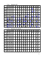
7.2.16.
Windows-1252 (West European Latin)
- 66 -
00h 01h 02h 03h 04h 05h 06h 07h 08h 09h 0Ah 0Bh 0Ch 0Dh 0Eh 0Fh
80h
€
‚
ƒ
„
… †
‡
ˆ
‰ Š
‹
Œ
Ž
90h
‘
’
“
”
•
– —
˜
™
š
›
œ
ž
Ÿ
A0h
¡
¢
£
¤
¥
¦
§
¨
©
ª
«
¬
®
¯
¶
B0h
°
±
²
³
´
µ
·
¸
¹
º
»
¼ ½ ¾
¿
C0h
À
Á
Â
Ã
Ä
Å Æ Ç
È
É
Ê
Ë
Ì
Í
Î
Ï
D0h
Ð Ñ Ò Ó Ô Õ Ö
×
Ø Ù
Ú
Û
Ü
Ý
Þ
ß
E0h
à
á
â
ã
ä
å æ
ç
è
é
ê
ë
ì
í
î
ï
F0h
ð
ñ
ò
ó
ô
õ
÷
ø
ù
ú
û
ü
ý
þ
ÿ
7.2.17.
ö
Windows-1253 (Greek)
00h 01h 02h 03h 04h 05h 06h 07h 08h 09h 0Ah 0Bh 0Ch 0Dh 0Eh 0Fh
80h
€
‚
ƒ
„
… †
‡
‰
‹
™
›
©
«
¬
Ό ½ Ύ Ώ
90h
‘
’
“
”
•
– —
A0h
΅
Ά
£
¤
¥
¦
§
¨
–
®
¯
B0h
°
±
²
³
´
µ
¶
·
Έ Ή
Ί
»
C0h
ΐ
Α
Β
Γ
Δ
Ε
Ζ
Η
Θ
Ι
Κ
Λ Μ Ν
Ξ
Ο
D0h
Π
Ρ
Σ
Τ
Υ
Φ
Χ
Ψ Ω
Ϊ
Ϋ
ά
έ
ή
ί
E0h
ΰ
α
β
γ
δ
ε
ζ
η
θ
ι
κ
Λ
μ
ν
ξ
ο
F0h
π
ρ
ς
σ
τ
υ
φ
χ
ψ
ω
ϊ
ϋ
ό
ύ
ώ
7.2.18.
- 67 -
Windows-1255 (Hebrew)
00h 01h 02h 03h 04h 05h 06h 07h 08h 09h 0Ah 0Bh 0Ch 0Dh 0Eh 0Fh
80h
€
‚
ƒ
„
… †
‡
ˆ
‰
‹
›
90h
‘
’
“
”
•
– —
˜
™
A0h
¡
¢
£
₪
¥
¦
§
¨
©
×
«
¬
®
¯
÷
»
¼ ½ ¾
¿
ֻ
ּ
ֽ
־
ֿ
–
B0h
°
±
²
³
´
µ
¶
·
¸
¹
C0h
ְ
ֱ
ֲ
ֳ
ִ
ֵ
ֶ
ַ
ָ
ֹ
D0h
׀
ׁ
ׂ
׃
װ
ױ
ײ
׳
״
,
:
;
.
!
?
E0h
א
ב
ג
ד
ה
ו
ז
ח
ט
י
ך
כ
ל
ם
מ
F0h
נ
ס
ע
ף
פ
ץ
צ
ק
ר
ש
ת
7.2.19.
ן
Windows-1257 (Baltic)
00h 01h 02h 03h 04h 05h 06h 07h 08h 09h 0Ah 0Bh 0Ch 0Dh 0Eh 0Fh
80h
€
‚
‘
90h
A0h
„
’
“
”
¢
£
¤
… †
•
‡
‰
‹
¨
ˇ
– —
™
›
¯
˛
–
® Æ
¦
§
Ø ©
Ŗ
«
¬
¸
B0h
°
±
²
³
´
µ
¶
·
ø
¹
ŗ
»
¼ ½ ¾ æ
C0h
Ą
Į
Ā Ć
Ä
Å
Ę
Ē Č
É
Ź
Ė
Ģ
Ķ
Ī
Ļ
D0h
Š Ń Ņ Ó Ō Õ Ö
×
Ų
Ł
Ś
Ū
Ü
Ż
Ž
ß
E0h
ą
į
ā
ć
ä
å
ę
ē
č
é
ź
ė
ģ
ķ
ī
ļ
F0h
š
ń
ņ
ó
ō
õ
ö
÷
ų
ł
ś
ū
ü
ż
ž
˙
- 68 -
8. Command Details
A.1. Overwrite mode
In this mode, the cursor will move towards the right and begin from the upper left position.
When the cursor has reached the end of the upper line, the cursor will move down to the
bottom left position to continue. When the cursor has reached the end of the bottom line, it
will move to up the upper left position and overwrite the previous characters.
A.2. Vertical scroll mode
In this mode, the cursor will move towards the right. The cursor will begin from the upper left
position until it has reached the end of the upper line. The cursor will then move down to the
bottom left position to continue until it has reached the end of the bottom line.
A.3. Horizontal scroll mode
In this mode, the extent of the cursor activity is bound by a predefined range, limited to the
upper line. (Please refer to Set or cancel window command), where the default window is
the whole upper line. The cursor will begin from the left-end of the range and move
rightward until it reached the end of the range, to continue, the characters that comes
thereafter will start pushing the previous characters leftward from the right-end, scrolling the
characters to the left.
A.4. Set the string display mode and write string to display
Set the string display mode, write to upper or lower line d1 d2 d3 … dn {1≦n≦20}. ‘A’
stands for the upper line, ‘B’ stands for the lower line. The string display mode will be
cancelled and the display will return to the previous mode after receiving CLR or CAN.
A.5. Upper line message continuous scroll
The message (previously defined) will scroll continuously in the horizontal direction until a
new command is received.
A.6. Move cursor left
When the current cursor is at the left-end position, this command operates differently
depending on the display mode.
Overwrite mode: When the cursor reached the left-end of the lower line, it will
continue to the right-end of the upper line, overwrite previous characters. When it
reached the left end of the upper line, it will continue to the right-end of the lower line.
Vertical scroll mode: When the cursor reached the left-end of the lower line, the lower
line will scroll up and replace the previous upper line, the lower line will be cleared and
the cursor will continue to the right end of the lower line.
Horizontal scroll mode: The cursor will remain stationary.
- 69 -
A.7. Move cursor right
Move the cursor to the right. When the cursor has reached the right-end, this command
operates differently depending on the display mode.
Overwrite mode: When the cursor has reached the right-end of the lower line, it will
continue to the left-end of the upper line and overwrite previous characters. When it
has reached the right-end of the upper line, it will continue to the right-end of the lower
line.
Vertical scroll mode: When the cursor has reached the right-end of the lower line, the
lower line will scroll up to replace the upper line, the lower line is cleared and ready to
continue characters thereafter.
Horizontal scroll mode: The cursor will remain stationary.
A.8. Move cursor up
Move the cursor up one line. When the cursor is on the upper line, this command operates
differently depending on the display mode.
Overwrite mode: The cursor is moved to the same column the lower line.
Vertical scroll mode: The characters displayed on the upper line is scrolled to the
lower line, and the upper line is cleared. The cursor will remain at the same position.
Horizontal scroll mode: The cursor will remain stationary.
A.9. Move cursor down
Move the cursor down one line. When the cursor is on the lower line, this command
operates differently depending on the display mode.
Overwrite mode: The cursor is moved to the same column on the upper line.
Vertical scroll mode: The characters displayed on the lower line are scrolled to the
upper line, and the lower line is cleared. The cursor will remain at the same position.
Horizontal scroll mode: The cursor will remain stationary.
A.10. Move cursor to home position
The cursor will move to the left-end position of the upper line.
A.11. Move cursor to left-most position
The cursor will be moved to the left-end position of the current line.
A.12. Move cursor to right-most position
The cursor will be moved to the right-end position of the current line.
A.13. Move cursor to bottom position
The cursor will be moved to the right-end position on the lower line.
- 70 -
A.14. Move cursor to specified position
The cursor will be moved to column x on line y.
A.15. Initialize display
The data in the input buffer will be cleared and reset from default.
A.16. Reset the window
Reset the window on the display.
When s=0, the window is cancelled (values: x1, x2, and y are not required.)
When s=1, the window will be reset (values: x1, x2, and y are required.)
The x1 and x2 set the position of the left column and right column, respectively, of the
window.
The y sets the upper line or the lower line of the window.
This function is valid within the horizontal mode.
A.17. Clear display screen and clear string mode
All the display characters will be cleared, and the string mode will be cancelled.
A.18. Clear current line and cancel string mode
The current line is cleared, and the string mode is cancelled.
A.19. Brightness adjustment
Adjust the brightness of the vacuum fluorescent display.
When n=3, brightness=70%
When n=4, brightness=100%
A.20. Set cursor ON or OFF
When n=0, cursor is OFF
When n=1, cursor is ON
- 71 -
9. Control Code Set
HEX
CODE
HEX
CODE
00H
NULL
10H
DLE
01H
SOH, MD1
11H
DC1
02H
STX, MD2
12H
DC2
03H
ETX, MD3
13H
DC3
04H
EOT, MD4
14H
DC4
05H
ENQ, MD5
15H
NAK
06H
ACK, MD6
16H
SYN
07H
BEL, MD7
17H
ETB
08H
BS, MD8
18H
CAN
09H
HT
19H
EM
0AH
LF
1AH
SUB
0BH
VT, HOM
1BH
ESC
0CH
FF, CLR
1CH
FS
0DH
CR
1DH
GS
0EH
SO, SLE1
1EH
RS, SF1
0FH
SI, SLE2
1FH
US, SF2
- 72 -