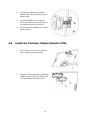
Download User Manual - Support Technique AURES
Transcript
User Manual Version 1.0 March 2013 SANGO Copyright 2013 All Rights Reserved Manual Version 1.0 The information contained in this document is subject to change without notice. We make no warranty of any kind with regard to this material, including, but not limited to, the implied warranties of merchantability and fitness for a particular purpose. We shall not be liable for errors contained herein or for incidental or consequential damages in connection with the furnishing, performance, or use of this material. This document contains proprietary information that is protected by copyright. All rights are reserved. No part of this document may be photocopied, reproduced or translated to another language without the prior written consent of the manufacturer. TRADEMARK Intel®, Pentium® and MMX are registered trademarks of Intel® Corporation. Microsoft® and Windows® are registered trademarks of Microsoft Corporation. Other trademarks mentioned herein are the property of their respective owners. i Safety IMPORTANT SAFETY INSTRUCTIONS 1. 2. 3. 4. 5. 6. 7. 8. 9. To disconnect the machine from the electrical Power Supply, turn off the power switch and remove the power cord plug from the wall socket. The wall socket must be easily accessible and in close proximity to the machine. Read these instructions carefully. Save these instructions for future reference. Follow all warnings and instructions marked on the product. Do not use this product near water. Do not place this product on an unstable cart, stand, or table. The product may fall, causing serious damage to the product. Slots and openings in the cabinet and the back or bottom are provided for ventilation; to ensure reliable operation of the product and to protect it from overheating. These openings must not be blocked or covered. The openings should never be blocked by placing the product on a bed, sofa, rug, or other similar surface. This product should never be placed near or over a radiator or heat register, or in a built-in installation unless proper ventilation is provided. This product should be operated from the type of power indicated on the marking label. If you are not sure of the type of power available, consult your dealer or local power company. Do not allow anything to rest on the power cord. Do not locate this product where persons will walk on the cord. Never push objects of any kind into this product through cabinet slots as they may touch dangerous voltage points or short out parts that could result in a fire or electric shock. Never spill liquid of any kind on the product. CE MARK This device complies with the requirements of the EEC directive 2004/108/EC with regard to “Electromagnetic compatibility” and 2006/95/EC “Low Voltage Directive” FCC This device complies with part 15 of the FCC rules. Operation is subject to the following two conditions: (1) This device may not cause harmful interference. (2) This device must accept any interference received, including interference that may cause undesired operation ii CAUTION ON LITHIUM BATTERIES There is a danger of explosion if the battery is replaced incorrectly. Replace only with the same or equivalent type recommended by the manufacturer. Discard used batteries according to the manufacturer’s instructions. Battery Caution Risk of explosion if battery is replaced by an incorrectly type. Dispose of used battery according to the local disposal instructions. Safety Caution Note: To comply with IEC60950-1 Clause 2.5 (limited power sources, L.P.S) related legislation, peripherals shall be 4.7.3.2 "Materials for fire enclosure" compliant. 4.7.3.2 Materials for fire enclosures For MOVABLE EQUIPMENT having a total mass not exceeding 18kg.the material of a FIRE ENCLOSURE, in the thinnest significant wall thickness used, shall be of V-1 CLASS MATERIAL or shall pass the test of Clause A.2. For MOVABLE EQUIPMENT having a total mass exceeding 18kg and for all STATIONARY EQUIPMENT, the material of a FIRE ENCLOSURE, in the thinnest significant wall thickness used, shall be of 5VB CLASS MATERIAL or shall pass the test of Clause A.1 LEGISLATION AND WEEE SYMBOL 2012/19/EU Waste Electrical and Electronic Equipment Directive on the treatment, collection, recycling and disposal of electric and electronic devices and their components. The crossed dustbin symbol on the device means that it should not be disposed of with other household wastes at the end of its working life. Instead, the device should be taken to the waste collection centers for activation of the treatment, collection, recycling and disposal procedure. To prevent possible harm to the environment or human health from uncontrolled waste disposal, please separate this from other types of wastes and recycle it responsibly to promote the sustainable reuse of material resources. Household users should contact either the retailer where they purchased this product, or their local government office, for details of where and how they can take this item for environmentally safe recycling. Business users should contact their supplier and check the terms and conditions of the purchase contract. This product should not be mixed with other commercial wastes for disposal. iii Revision History Revision Date V1.0 March, 2013 Description iv Release Table of Contents 1 Item Checklist................................................1 1-1 1-2 Standard Items............................................................................... 1 Optional Items ................................................................................ 2 2 System View...................................................3 2-1 2-2 2-3 2-4 2-5 Front View ....................................................................................... 3 Rear View ........................................................................................ 4 Side View ........................................................................................ 4 Dimension....................................................................................... 5 I/O View........................................................................................... 6 3 Installing the Power Adapter ........................7 4 Peripherals Installation.................................8 4-1 4-2 4-3 4-4 4-5 Install the MSR Module ................................................................. 8 Install the 2-in-1 MSR+ iButton Module ....................................... 9 Install the 2-in-1 MSR+ Addimat Reader...................................... 9 Install the Customer Display (Graphic LCM)...............................10 Install the Cash Drawer................................................................12 5 Specification ............................................... 14 6 Configuration .............................................. 16 6-1 6-2 C95 Motherboard.........................................................................16 C96 Motherboard.........................................................................21 Appendix A: Driver Installation....................................26 Appendix B: Customer Display Command Settings...27 v 1 Item Checklist 1-1 Standard Items a. System b. Power adapter (65W) c. Power cable d. COM-RJ45 cable (x4) e. Manual CD 1 1-2 Optional Items a. MSR module b. 2-in-1 MSR+ iButton module c. d. Customer display ( Graphic LCM ) 2-in-1 MSR+ Addimat reader 2 2 System View 2-1 Front View View angle of 0 degree Number Description 1 Touch screen 2 Power button 3 System box 4 USB x2 5 Stand base 3 2-2 Rear View Number Description 6 8 Customer display (Graphic LCM) dummy cover MSR / 2-in-1 MSR+ iButton / 2-in-1 MSR+ addimat reader dummy cover Lock button of the system box 9 Entry of the power adapter 7 2-3 Side View 4 2-4 Dimension 5 2-5 I/O View Number Description a DC jack b Cash drawer c USB x 4 d LAN e COM1~4 (from left to right) f Display port 6 3 Installing the Power Adapter The system is equipped with a 65W power adapter. Please plug it into the system as shown below. 1. Press the button to open the system box cover. 2. Find the power connector on the I/O panel.(refer to chapter 2-5 a. ) and connect the power adapter directly to the DC-IN connector. 3. Close the system box cover. Make sure the power adapter is threaded through the hole as shown in the picture. 7 4 Peripherals Installation 4-1 Install the MSR Module MSR module can be installed to either side of the system. Choose one side and follow the steps below. Make sure the unit is powered down before starting. 1. Remove the dummy cover first and then unfasten the screws (x2). 2. Connect the MSR cable (x1) to the connector on the system side. 3. Insert the MSR module in place and fasten the screws (x2) on the back to secure the module. 4. Finally attach the MSR dummy cover back to place. 8 4-2 4-3 Install the 2-in-1 MSR+ iButton Module 1. Remove the dummy cover first and then unfasten the screws (x2). 2. Connect the MSR+ iButton cables (x2) to the connector on the system side. 3. Insert the MSR+ iButton module in place and fasten the screws (x2) on the back to secure the module. 4. Finally attach the MSR dummy cover back to place. Install the 2-in-1 MSR+ Addimat Reader 1. Remove the dummy cover first and then unfasten the screws (x2). 9 4-4 2. Connect the addimat key reader cables (x2) to the connector on the system side. 3. Insert the addimat key reader in place and fasten the screws (x2) on the back to secure the module. 4. Finally attach the MSR dummy cover back to place. Install the Customer Display (Graphic LCM) 1. Remove the dummy cover first and then unfasten the screws (x2). 2. Attach the customer display (Graphic LCM) bracket to the back side of the LCD and fasten the screws (x3). 10 3. Connect the customer display (Graphic LCM) cable to the connector on system side. 4. Attach the customer display (Graphic LCM) to the bracket and fasten the screws (x4) to secure it to the system. 11 4-5 Install the Cash Drawer You can install a cash drawer through the cash drawer port. Please verify the pin assignment before installation. Cash Drawer Pin Assignment Pin 1 2 3 4 5 6 Signal GND DOUT bit0 DIN bit0 12V / 19V DOUT bit1 GND Cash Drawer Controller Register The Cash Drawer Controller use one I/O addresses to control the Cash Drawer. Register Location: 48Ch Attribute: Read / Write Size: 8bit BIT BIT7 BIT6 BIT5 BIT4 Attribute Reserved Read Reserved 7 X 6 5 4 X X 3 2 1 0 X X BIT3 BIT2 Write BIT1 BIT0 Reserved Reserved Cash Drawer “DOUT bit0” pin output control Cash Drawer “DOUT bit1” pin output control Reserved Cash Drawer “DIN bit0” pin input status Reserved 12 Bit 7: Reserved Bit 6: Cash Drawer “DIN bit0” pin input status. = 1: the Cash Drawer closed or no Cash Drawer = 0: the Cash Drawer opened Bit 5: Reserved Bit 4: Reserved Bit 3: Cash Drawer “DOUT bit1” pin output control. = 1: Opening the Cash Drawer = 0: Allow close the Cash Drawer Bit 2: Cash Drawer “DOUT bit0” pin output control. = 1: Opening the Cash Drawer = 0: Allow close the Cash Drawer Bit 1: Reserved Bit 0: Reserved Note: Please follow the Cash Drawer control signal design to control the Cash Drawer. Cash Drawer Control Command Example Use Debug.EXE program under DOS or Windows98 Command Cash Drawer O 48C 04 Opening O 48C 00 Allow to close Set the I/O address 48Ch bit2 =1 for opening Cash Drawer by “DOUT bit0” pin control. Set the I/O address 48Ch bit2 = 0 for allow close Cash Drawer. Command Cash Drawer I 48C Check status The I/O address 48Ch bit6 =1 mean the Cash Drawer is opened or not exist. The I/O address 48Ch bit6 =0 mean the Cash Drawer is closed. 13 5 Specification Model Name Motherboard CPU support Chipset System memory Graphic memory LAN controller SANGO C95 Intel Sandy Bridge 1047UE LLC 2MB Intel Ivy Bridge i3 -3217U 1.8G, LLC 3MB Intel Express chip HM76 DDR3 2GB (1047UE CPU), max. 8GB DDR3 4GB (i3-3217U CPU ), max. 8GB Intel HD Graphic (Gen. 7, DX11, OpenGL 3.1, OCL 1.1) C96 Intel CedarView D2550 1.86G, L2 Cache 1MB Intel NM10 DDR3 2GB, max. 4GB DX10.1, Graphic core speed at 640MHz Realtek RTL8111E-VL-CG 10/100/1000 baseT LAN Realtek ALC 662-GR HD codec Intel 82579LM (Phy) Audio controller I/O controller Winbond W83627UHG BIOS Phoenix UEFI LCD Touch Panel LCD size 15" LED LCD Brightness 300nits Maximal resolution 1024 x 768 Touch screen type 15" True flat resistive touch/True flat projected capacitive touch Tilt angle 0° ~ 89° Storage HDD One 2.5" SATA HDD bay Expansion mini PCI-E socket 1 Front I/O Power button 1 Power LED 1 USB 2 (USB 3.0/2.0) 2 (USB 2.0) 2 (USB 2.0) 2 (USB 3.0/2.0 ) 4 (USB 2.0) Rear I/O USB Serial / COM LAN DC jack Cash drawer RJ45 COM x4 (COM1 standard RS-232, COM2/COM3/COM4 powered COM with enable option in BIOS. Power on pin 9 (DB9)/ pin 10 (RJ45) selectable to +5V / 12V by jumper on the motherboard. Default setting: +5V) 1 x RJ45 (10/100/1000 Mbps Giga LAN) 1 x DC-19V (4 pins with lock) 1 x RJ-11 (12V or 19V, selection by jumper. Default setting: 19V) 14 Model Name Motherboard SANGO C95 C96 Display port 1 Power Power adapter Ext. 65W adapter 19V/4.7A Peripherals MSR module 3 track MSR (USB) 2-in-1 reader MSR+ iButton / MSR+ Addimat reader (USB) Customer display Customer display (Graphic LCM) (USB) Communication Wireless LAN 802.11 b/g/n wireless LAN card (Option) Certifications CME & DBT FCC/CE Class A, LVD Environment Operating temperature Storage temperature Humidity Dimension (W x D x H) 0oC ~ 35 oC (32 oF ~ 95 oF) -20 oC ~ 60 oC (-4 oF ~ 140 oF) 20% ~ 85% RH non condensing LCD 0 degree : 401.9 x 297.9 x 221.9 mm LCD 89 degree : 401.9 x 262 x 424 mm Weight (N.W./G.W.) 10kg / 11kg Windows XP, POS Ready 2009, XP Windows XP, POS Ready 2009, XP OS support Embedded, XP professional for Embedded, Embedded, XP professional for Embedded, Linux, Windows7, POSReady7, Windows 8 Windows7 (32bit), POSReady7 (32bit) * This specification is subject to change without prior notice. 15 6 Configuration 6-1 C95 Motherboard 6-1-1 Motherboard Layout C95 V1.0 16 6-1-2 Connectors & Functions Connectors CN3 CN4 CN5 CN7 CN10 CN12 PWR1 RJ11_1 RJ45_1 RJ45_2 DDR3_A1 SATA1/2 USB1 USB2 USB3 USB4 JP1 JP2 JP3 JP4 JP5 JP6 JP7/JP8 JP9 JP10 JP11 SW1 DP1 Functions Power button(Internal) SATA power connector I/O board connector Speaker & MIC connector Printer port connector EC SMBus connector +19V DC jack Cash drawer connector LAN connector COM1/COM2/COM3/COM4 DDR3 SO-DIMM SATA connector USB3.0 port2 USB3.0 port3 USB3.0 port0/1 USB4 USB5 CMOS operation mode Auto button setting LCD ID setting Inverter select H/W reset ME debug mode VGA connector (internal) Cash drawer power setting COM2 power setting COM3/COM4 power setting Power button Display port 17 6-1-3 Jumper Settings LCD Backlight Type JP4 Function (1-2) (3-4) ▲LED W/BN CCFL W/BN Cash Drawer Power Setting JP9 Function (1-2) (3-4) ▲+19V +12V ME update JP6 Function (1-2) ▲Lock Un-lock COM2 Power Setting JP10 Function (1-2) ▲COM2 +5V COM2 +12V ▲ = Manufacturer Default Setting OPEN 18 SHORT (3-4) COM 3 & COM4 Power Setting JP11 Function (1-2) (3-4) (5-6) (7-8) ▲COM3 +5V COM3 +12V ▲COM4 +5V COM4 +12V COM2/COM3/COM4 Power Setting COM2, COM3 and COM4 can be set to provide power to your serial device. The voltage can be set to +5V or +12V by setting jumper JP10 and JP11 on the motherboard. When enabled, the power is available on pin 10 of the RJ45 serial connector. If you use the serial RJ45 to DB9 adapter cable, the power is on pin 9 of the DB9 connector. By default, the power option is disabled in the BIOS. 1. Power on the system, and press the <DEL> key when the system is booting up to enter the BIOS Setup utility. 2. Select the Advanced tab. 3. Select VGA/COM Power and LCD Brightness Configuration Ports and press <Enter> to go to display the available options. 4. To enable the power, select COM2 , COM3 or COM4 Power setting and press <Enter>. Select Power and press <Enter>. Save the change by pressing F10. 19 LCD ID Setting Panel Number Resolution 4 1024 x 768 LVDS Bits Channel 24 Single ▲ = Manufacturer Default Setting OPEN 20 Output Interface LVDS Panel SHORT JP3 (1-2) (3-4) (5-6) (7-8) (9-10) 6-2 C96 Motherboard 6-2-1 Motherboard Layout C96 V1.0 21 
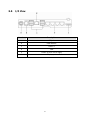
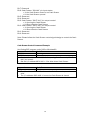
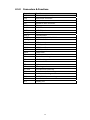
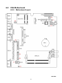
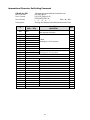
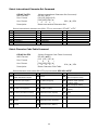
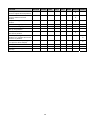
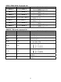
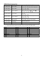
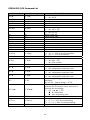
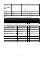
6-2-2 Connectors & Functions Connectors CN4 CN5 CN8 CN9 CN12 CN15 PWR1 RJ11_1 RJ45_1 RJ45_2 DDR3_A1 SATA1/2 SKT1 USB1 USB2 USB3 USB4 JP1 JP2 JP3 JP4 JP5/JP6 JP7 JP8 JP9 JP10 SW1 DP1 Functions Power button (internal) SATA power connector I/O board connector Speaker & MIC connector SATA LED connector Printer port connector +19V DC jack Cash drawer connector LAN connector COM1/COM2/COM3/COM4 DDR3 SO-DIMM SATA connector BIOS connector USB3 USB2 USB6 USB7 USB4 USB5 Auto button setting LCD ID setting Inverter select H/W reset VGA connector (internal) COM3/COM4 power setting COM2 power setting Cash drawer power setting CMOS operation mode Power button Display port 22 6-2-3 Jumper Settings LCD Backlight Type JP3 Function (1-2) (3-4) ▲LED W/BN CCFL W/BN Cash Drawer Power Setting JP9 Function (1-2) (3-4) ▲+19V +12V COM2 Power Setting JP8 Function (1-2) ▲COM2 +5V COM2 +12V ▲ = Manufacturer Default Setting OPEN 23 SHORT (3-4) COM 3 & COM4 Power Setting JP7 Function (1-2) (3-4) (5-6) (7-8) ▲COM3 +5V COM3 +12V ▲COM4 +5V COM4 +12V COM2/COM3/COM4 Power Setting COM2, COM3 and COM4 can be set to provide power to your serial device. The voltage can be set to +5V or +12V by setting jumper JP7 and JP8 on the motherboard. When enabled, the power is available on pin 10 of the RJ45 serial connector. If you use the serial RJ45 to DB9 adapter cable, the power is on pin 9 of the DB9 connector. By default, the power option is disabled in the BIOS. 1. Power on the system, and press the <DEL> key when the system is booting up to enter the BIOS Setup utility. 2. Select the Advanced tab. 3. Select VGA/COM Power and LCD Brightness Configuration Ports and press <Enter> to go to display the available options. 4. To enable the power, select COM2 , COM3 or COM4 Power setting and press <Enter>. Select Power and press <Enter>. Save the change by pressing F10. 24 LCD ID Setting Panel Number Resolution 7 1024 x 768 LVDS Bits Channel 24 Single ▲ = Manufacturer Default Setting OPEN 25 Output Interface LVDS Panel SHORT JP3 (1-2) (3-4) (5-6) (7-8) (9-10) Appendix A: Driver Installation To download the most recent drivers and utilities, and obtain advice regarding the installation of your equipment, please visit the AURES Technical Support Website: www.aures-support.fr (French) www.aures-support.fr/UK (English) www.aures-support.fr/GE (German) 26 Appendix B: Customer Display Command Settings Features 1. Data can be display on 20 columns x 2 lines(USA/Euro/Arabic Symbol) 2. White-Black color and large character are easy to see. 3. System command set provide stored in non-volatile Flash ROM that without the switches 4. Command emulation modes include: POS7300, EPSON ESC/POS, DSP800, ADM787/ ADM788, AEDEX/ EMAX, UTC, and CD5220. 5. Display area can be controlled by window function. 6. Provides an interface based in USB Virtual COM, (driver install request) 7. Reverse characters can be specified using the POS7300/EPSON command set. 27 Specification NO Item 1 Display method 2 Number of character 3 4 5 Character font Display color Brightness 6 Character type 7 8 9 10 11 12 Character size Power supply Power consumption MTBF Panel dimensions View area dimensions 13 Viewing angle 14 15 16 17 Operating temperature Operating Humidity Storage Temperature Storage Humidity Description White LED Backlight FSTN Negative Transmissive LCD 40 characters ( 20 x 2 Line ) 12 x 32 Dot matrix White-Black 1000 cd/m2 96 alphanumeric 28 kinds of international character set 6.33mm x 16.93mm USB +5V Power Supply 0.3 W 50,000 hours (power on time) 142.5 (W) x 51.7(H) x 14.9(D) mm 130.2mm (W) x 37.6mm (H) 30 ~ 60 degress (Vertical) -45 ~ 45 degrees (Horizontal) 5 ~ 45oC 30% ~ 85% -10 ~ 55 oC 10% ~ 85% 28 Interface USB Virtual COM. Install driver is necessary. Connector Pin Definition Connector type: Pitch 1.25mm 4 pin USB connector USB Pin Definition Pin # Definition 1 +5V_VBUS 2 USB_D3 USB_D+ 4 GND 29 Software Status Setting Commands When the device is POWER ON, it will read the Flash ROM Setting to set the Command Type, Baud Rate, Parity, Data Length, Demo Mode and International Character. User can re-set the Software Status Setting Commands as following, and Status Setting will be saving to Flash ROM: Baud Rate Setting Command STX 05 B n ETX ASCII Format Dec. Format Hex. Format Description /Change the baud rate setting/ STX 05 B n ETX [02] [05] [66] n [03] [02h][05h][42h] n 30h≦n≦33h [ 0 3 h ] Change the display communication baud rate. The baud rate setting can be selected from 4800 to 38400. n 31h 30h 37h 36h Baud rate 4800 9600 19200 38400 Parity Check Setting Command STX 05 P n ETX ASCII Format Dec. Format Hex. Format Description /Change the Parity check setting/ STX 05 P n ETX [02] [05] [80] n [03] [02h][05h][50h] n n=30h ~ 32h [ 0 3 h ] Change the display communication parity. Set 8 data bit and the parity set for even、odd or non-parity. n 31h 33h 35h Parity check None-parity Even-parity Odd-parity Data Length Setting Command STX 05 L n ETX ASCII Format Dec. Format Hex. Format Description /Change the Data Length Setting/ STX 05 L n ETX [02] [05] [76] n [03] [02h][05h][4Ch] n n=37h, 38h [ 0 3 h ] Change the display communication data length. Set 8-bits or 7-bits data length. n 37h 38h Data Length 7 bits 8 bits 30 International Character Set Setting Command STX 05 S n ETX ASCII Format Dec. Format Hex. Format Description n /Change the international character set/ STX 05 S n ETX [02] [05] [83] n [03] [02h][05h][53h] n 30h≦n≦4Ch [ 0 3 h ] Change the display international character font. Character Set (20h – 7Fh) 30h U.S.A. 31h 32h 33h 34h 35h 36h 37h 38h 39h 3Ah 3Bh 3Ch 3Dh 3Eh 3Fh 40h 41h 42h 43h 44h 45h 46h 47h 48h 49h 4Ah 4Bh FRANCE GERMANY U.K. DENMARK I SWEDEN ITALY SPAIN JAPAN NORWAY DENMARK II Slawie RUSSIA U.S.A. U.K. U.S.A. U.S.A. U.S.A. U.S.A. U.S.A. U.S.A. U.S.A. U.S.A. U.S.A. U.S.A. U.S.A. U.S.A. Arabic Code Table (80H-FFH) CP-437 (USA, Standard Europe) CP-858 (Multilingual + Euro Symbol) Katakana CP-858 (Multilingual+ Euro Symbol) CP-860 (Portuguese) Greek CP-852 (Hungary) CP-862 (Hebrew) CP-863 (Canadian-French) CP-865 (Nordic) CP-866 (Cyrillic) Windows-1251 (Cyrillic) Windows-1252 (West European Latin) Windows-1255 (Hebrew) Windows-1257 (Baltic) Windows-1253 (Greek) Windows-1250 (East European Latin) Windows-1254 (Turkish) 31 Note Select International Character Set Command STX 05 T n ETX ASCII Format Dec. Format Hex. Format Description /Select International Character Set Command/ STX 05 T n ETX [02] [05] [84] n [03] [02h][05h][54h] n 00h≦n≦0Dh [ 0 3 h ] Select International Character Set Select international character set (20H~7Fh) by command “STX 05 T n ETX” n 00h 01h 02h 03h 04h 05h International character set U.S.A. FRANCE GERMANY U.K. DENMARK I SWEDEN n 06h 07h 08h 09h 0Ah 0Bh International character set ITALY SPAIN JAPAN NORWAY DENMARK II SLAVONIC International character set n 0Ch RUSSIA 0Dh ARABIC Select Character Code Table Command STX 05 U n ETX ASCII Format Dec. Format Hex. Format Description /Select Character Code Table Command/ STX 05 U n ETX [02] [05] [85] n [ 0 3 ] [02h][05h][55h] n 00h≦n≦15h [ 0 3 h ] Select Character Code Table Select character code table (80H~FFh) by command “STX 05 U n ETX” n Character code table CP-437 00h (USA, Standard Europe) n Character code table 08h Greek n Character code table Windows-1252 10h (West European Latin) 01h Katakana (for Japan) 09h CP-852 (Hungary) 11h Windows-1253 (Greek) 02h CP-850 (Multilingual) 0Ah CP-862 (Hebrew) 12h 03h CP-860 (Portuguese) 0Bh CP-866 (Cyrillic) 04h CP-863 (Canadian-French) 0Ch Windows-1251 (Cyrillic) 05h CP-865 (Nordic) 0Dh Windows-1254 (Turkish) 06h Slawie 0Eh Windows-1255 (Hebrew) 07h Russia 0Fh Windows-1257 (Baltic) 32 Windows-1250 (East European Latin) CP-858 (Multilingual+ Euro 13h Symbol) 14h Arabic Command Type Setting Command STX 05 C n ETX ASCII Format Dec. Format /Change the command type setting/ STX 05 C n ETX [02] [05] [67] n [03] [02h][05h][43h] n 30h≦ n ≦37h [ 0 3 h ] This command will change the command type and initialize the display. The display emulation mode is based on DSP800/ ESC/ ADM 787/ POS7300/ AEDEX/ UTC/ CD5220 mode. Hex. Format Description n 32h 31h 33h 30h Command Type POS7300 ESC/POS ADM 787 DSP800 n 34h 35h 36h 37h Command Type AEDEX UTC/P UTC/S CD5220 Run Demo message STX 05 D 08 ETX ASCII Format Dec. Format Hex. Format Description /Run demo message/ STX 05 D 08 ETX [02][05][68][08][03] [02h][05h][44h][08h][03h] Run demo message for the display. The display emulation mode is based on PA7300, DSP800, EPSON ESC/POS, CD5220 command type. Show Firmware Version STX 05 V 01 ETX ASCII Format Dec. Format Hex. Format Description /Show Firmware Version/ STX 05 V 01 ETX [02][05][86][01][03] [02h][05h][56h][01h][03h] Show firmware version. Graphic LCM Contrast Setting STX F7 SOH n NUL ASCII Format Dec. Format Hex. Format Description /Set Graphic LCM Contrast Value/ STX F7 SOH n NUL [02][247][01][n][00] [02h][F7h][01h][n][00h] Set Graphic LCM Contrast. Setting Value Range: 00h ~ 3Fh Default Value is 20h 33 Display Logo Command STX F7 SOH n NUL ASCII Format Dec. Format Hex. Format Description /Display Logo Command/ STX FC 55 AA 55 AA [02][252][85][170][85][170] [02h][FCh][55h][AAh][55h] [AAh] Displays the logo. Please ensure that the logo has been set with the Customer Display configuration utility before using this command. 34 Command List Table Command Command Set Move cursor right Move cursor left Move cursor up Move cursor down Move cursor to right-most position Move cursor to left-most position Move cursor to home position Move cursor to bottom position Move cursor to specified position Clear display screen Clear cursor line Blink display screen Initialize display Select character code table Select international character set Select/cancel reverse character Overwrite mode Vertical scroll mode Horizontal scroll mode Set/cancel the window range Set starting/ending position of macro definition Execute and quit macro Execute self-test Display time Display time continuously Display position Cursor on/off Change to UTC enhanced mode Change to UTC standard mode Write string to upper line Upper line message continuous scroll Bottom line message scroll continuously Message vertical down scroll continuously Message vertical upper scroll continuously Carriage return Line feed Back space Horizontal tab Command type select Upper line message scroll once pass Change attention code Two line display POS7300 CD5220 EPSON D101 O O O O O O O O O O O O O O O O O O O O O O O O O O O O O O O O O O O O O O O O O O O O O O O O O O O O O O O O O O O UTC/S UTC/P AEDEX ADM788 DSP800 O O O O O O O O O O O O O O O O O O O O O O O O O O O O O O O O O O O O O O O O O O O O O O O O 35 O O O O O O O O O Command Command Set Clear upper line and move cursor to upper left-end position Clear bottom line and move cursor to bottom left-end position Set period to upper line, last n position Set line blinking, upper line Clear line blinking, upper line Clear field 1 and move cursor to field 1, first position Clear field 2 and move cursor to field 2,first position Clear display range from n position to m position and move cursor to n position Save the current displaying data to n layer for demo display Specify period Specify comma Specify semicolon (period + comma) POS7300 CD5220 EPSON D101 UTC/S UTC/P AEDEX ADM788 DSP800 O O O O O O O O O O O O O O O O O 36 Command Details POS7300 Series Command List Command Code (hex) ESC F A [DATA] CR 1B 46 41 [DATA] 0D ESC F B [DATA] CR 1B 46 42 [DATA] 0D ESC F D [DATA] CR ESC F O [DATA] CR 1B 46 44 [DATA] 0D 1B 46 4F [DATA] 0D ESC P x y 1B 50 x y ESC _ n 1B 5F n ESC DC1 ESC DC2 ESC DC3 ESC @ 1B 11 1B 12 1B 13 1B 40 US MD1 n 1F 01 n US MD2 n 1F 02 n US DC1 n 1F 11 n US DC2 n 1F 12 n US , n 1F 2C n US . n 1F 2E n US ; n 1F 3B n US @ 1F 40 US E n 1F 45 n US T h m 1F 54 h m US U 1F 55 US r n 1F 72 n NULL H 0 48 Function Description Write string to upper line Maximal [DATA] length is 40 Write string to lower line Maximal [DATA] length is 40 Upper line message scroll continuously Maximal [DATA] length is 40 Bottom line message scroll continuously Maximal [DATA] length is 40 Move cursor to specified position x = 1 ~ 14h, for columns location. y = 1 ~ 2, for lines location. Set cursor on/off n = 00 ~ 01 Overwrite mode Vertical scroll mode Horizontal scroll mode Initialize display Message vertical upper scroll continuously n = 01 ~ 0Ch Message vertical down scroll continuously n = 01 ~ 0Ch Set line blinking n = ’1’ ~ ’2’ n = ’1’ up line n = ’2’ low line Clear line blinking n = ’1’ ~ ’2’ n = ’1’ up line n = ’2’ low line Specify comma n = a displayable character code Specify period n = a displayable character code Specify semicolon (period + comma) n = a displayable character code Execute self - test Blink display screen n = 00h ~ FFh n = 0 for no blink Display time 0 ≦ h ≦ 17h, for hours setting. 0 ≦ m ≦ 3Bh, for minutes setting. Display time continuously Select/cancel reverse character. n = 00,01 Move cursor up 37 Command NULL K NULL M NULL P NULL G NULL O BS HT LF HOM US B CLR CLR CR CAN Code (hex) 0 4B 0 4D 0 50 0 47 0 4F 08 09 0A 0B 1F 42 0C 12 0D 18 DLE n 10 n ESC W n s x1 y1 x2 y2 1B 57 n s x1 y1 x2 y2 ESC R n 1B 52 n ESC t n 1B 74 n Function Description Move cursor left Move cursor right Move cursor down Move cursor to left-most position Move cursor to right-most position Back space Horizontal tab Line feed Move cursor to home position Move cursor to bottom position Clear display screen Carriage return Clear cursor line, and clear string mode Display position n = 0 ~ 27h, for location. Set or cancel the window range n = 1 ~ 4, for window number s = 0: cancel s = 1: set 1 ≦ x1 ≦ x2 ≦ 14h, for columns location. 1 ≦ y1 ≦ y2 ≦ 2, for lines location. Select international character set (20H~7Fh). n = 00 ~ 0Dh. See note *1 Select character code table (80H~FFh). n = 00 ~ 15h. See note *2 38 Note: 1. Select international character set (20H~7Fh) by command “ESC R n” n International character set n International character set n International character set 00h U.S.A. 05h SWEDEN 0Ah DENMARK II 01h FRANCE 06h ITALY 0Bh SLAVONIC 02h GERMANY 07h SPAIN 0Ch RUSSIA 03h U.K. 08h JAPAN 0Dh ARABIC 04h DENMARK I 09h NORWAY 2. Select character code table (80H~FFh) by command “ESC t n” n 00h Character code table CP-437 (USA, Standard Europe) n Character code table n Character code table Windows-1252 (West European Latin) 08h Greek 10h 01h Katakana (for Japan) 09h CP-852 (Hungary) 11h Windows-1253 (Greek) 02h CP-850 (Multilingual) 0Ah CP-862 (Hebrew) 12h 03h CP-860 (Portuguese) 0Bh CP-866 (Cyrillic) 04h CP-863 (Canadian-French) 0Ch Windows-1251 (Cyrillic) 05h CP-865 (Nordic) 0Dh Windows-1254 (Turkish) 06h Slawie 0Eh Windows-1255 (Hebrew) 07h Russia 0Fh Windows-1257 (Baltic) 39 Windows-1250 (East European Latin) CP-858 13h (Multilingual+ Euro Symbol) 14h Arabic CD5220 Standard Mode Command List Command ESC DC1 US SOH ESC DC2 US STX ESC DC3 US ETX Code (hex) 1B 11 1F 01 1B 12 1F 02 1B 13 1F 03 ESC Q A [DATA] CR 1B 51 41 [DATA] 0D ESC Q B [DATA] CR 1B 51 42 [DATA] 0D ESC Q D [DATA] CR ESD [ D BS ESC [ C HT ESC [ A US LF ESC [ B LF ESC [ H HOM ESC [ L CR ESC [ R US CR ESC [ K US B 1B 5B 44 08 1B 5B 43 09 1B 5B 41 1F 0A 1B 5B 42 0A 1B 5B 48 0B 1B 5B 4C 0D 1B 5B 52 1F 0D 1B 5B 4B 1F 42 ESC # n 1B 23 n US @ 1F 40 US E n 1F 45 n ESC I x y 1B 6C x y US $ x y 1F 24 x y ESC # n 1B 23 n US E n 1F 45 n ESC I x y 1B 6C x y ESC @ 1B 40 1B 51 44 [DATA] 0D Function Description Overwrite mode Vertical scroll mode Horizontal scroll mode Set the string display mode, write string to upper line. *1 Maximal [DATA] length is 20 Set the string display mode, write string to lower line. *1 Maximal [DATA] length is 20 Upper line message scroll continuously. *1 *2 Maximal [DATA] length is 40 Move cursor left Move cursor right Move cursor up Move cursor down Move cursor to home position Move cursor to left-most position Move cursor to right-most position Move cursor to bottom position Command type select n = 30h ~ 37h Execute self test Blink display screen n = 00h ~ FFh n = 0 for no blink Move cursor to specified position x = 1 ~ 14h, for columns location. y = 1,2, for lines location. Command type select n = 30h ~ 37h Blink display screen n = 00h ~ FFh n = 0 for no blink Move cursor to specified position x = 1 ~ 14h, for columns location. y = 1,2, for lines location. Initialize display 40 Command Code (hex) ESC W s x1 x2 y 1B 57 s x1 x2 y CLR CAN 0C 18 ESC _ n 1B 5F n ESC f n 1B 66 n ESC c n 1B 63 n Function Description Set or cancel the window range at horizontal scroll mode 1 ≦ x1 ≦ x2 ≦ 14h, for columns location. y = 1~2, for lines location. s = 0: cancel s = 1: set Clear display screen, and clear string mode Clear cursor line, and clear string mode Set cursor on/off n = 1: cursor on n = 0: cursor off Select international Character About n, refer. *3 Select character code table About n, refer. *4 Note: 1. While using command “ESC Q A” or “ESC Q B”, other commands cannot be used except when using command “CLR” or “CAN” to change operating mode. 2. When using command “ESC Q D”, the upper line message will scroll continuously until a new command is received, it will then clear the upper line and move the cursor to the upper left-end position. 3. Select the international Character set (20h – 7Fh) by command “ESC f n”. Parameter “n” Character Hex ‘A’ 41h ‘G’ 47h ’I’ 49h ‘J’ 4Ah ‘U’ 55h ‘F’ 46h ‘S’ 53h ‘N’ 4Eh International Character Set U.S.A. Germany Italy Japan U.K. France Spain Norway Parameter “n” Character Hex ‘W’ 57h ‘D’ 44h ‘E’ 45h ‘L’ 4Ch ‘R’ 52h ‘B’ 42h 41 International Character Set Sweden Denmark I Denmark II Slavonic Russia Arabic 4. Select character code table (80H-FFH) by command “ESC c n”. Parameter “n” character Code Table Character Hex ‘A’ 41h Compliance with ASCII code (CP-437) ‘J’ 4Ah Compliance with JIS code (Katakana) ‘L’ 4Ch Compliance with Slawie code ‘R’ 52h Compliance with RUSSIA code ‘M’ 4Dh CP-850 (Multilingual) ‘P’ 50h CP-858 (Multilingual+ Euro Symbol) ‘p’ 70h CP-860 (Portuguese) ‘F’ 46h CP-863 (Canadian-French) ‘N’ 4Eh CP-865 (Nordic) ‘u’ 75h CP-852 (Hungary) ‘H’ 48h CP-862 (Hebrew) ‘C’ 43h CP-866 (Cyrillic) ‘G’ 47h Greek ‘c’ 63h Windows-1251 (Cyrillic) ‘W’ 57h Windows-1252 (West European Latin) ‘h’ 68h Windows-1255 (Hebrew) ‘B’ 42h Windows-1257 (Baltic) ‘g’ 67h Windows-1253 (Greek) ‘E’ 45h Windows-1250 (East European Latin) ‘T’ 54h Windows-1254 (Turkish) ‘I’ 49h Arabic 42 UTC Standard Mode Command List Command Code (hex) BS HT LF CR 08 09 0A 0D DLE n 10 n DC1 DC2 DC3 DC4 US ESC d 11 12 13 14 1F 1B 64 Function Description Back space Horizontal tab Line feed Carriage return Display position n = 0 ~ 27h, for location. Over write display mode Vertical scroll mode Cursor on Cursor off Clear display Change to UTC enhanced mode UTC Enhanced Mode Command List Command Code (hex) ESC u A [DATA] CR 1B 75 41 [DATA] 0D ESC u B [DATA] CR ESC u D [DATA] CR ESC u E h h : m m CR 1B 75 42 [DATA] 0D 1B 75 44 [DATA] 0D 1B 75 45 h h ':' m m 0D ESC u F [DATA] CR 1B 75 46 [DATA] 0D ESC u H n m CR 1B 75 48 n m 0D ESC u I [DATA] CR 1B 75 49 [DATA] 0D ESC RS CR 1B 0F 0D Function Description Upper line display Maximal [DATA] length is 20 Bottom line display Maximal [DATA] length is 20 Upper line message scroll continuously Maximal [DATA] length is 40 Display time h, m = '0' ~ '9' Upper line message scroll Once pass Maximal [DATA] length is 40 Change attention code n = 1 ~ 20h m = 1 ~ 20h Two line display Maximal [DATA] length is 40 Change to UTC standard mode 43 AEDEX/EMAX Mode Command List Command Code (hex) ! # 1 [DATA] CR 21 23 31 [DATA] 0D ! # 2 [DATA] CR 21 23 32 [DATA] 0D ! # 4 [DATA] CR 21 23 34 [DATA] 0D ! # 5 h h : m m CR 21 23 35 h h ':' m m 0D ! # 8 n m CR 21 23 38 n m 0D ! # 9 [DATA] CR 21 23 39 [DATA] 0D ! # 6 [DATA] CR 21 23 36 [DATA] 0D Function Description Upper line display Maximal [DATA] length is 20 Bottom line display Maximal [DATA] length is 20 Upper line message scroll Maximal [DATA] length is 60 Display time h, m = '0' ~ '9' Change attention code n, m = 1 ~ 20 Two line display Maximal [DATA] length is 40 Upper line message scroll once pass Maximal [DATA] length is 60 ADM787/788 mode command list Command Code (hex) CLR CR 0C 0D SLE1 0E SLE2 0F DC0 n 10 n DC1 n 11 n DC2 n 12 n SF1 1E SF2 1F Function Description Clear display Carriage return Clear upper line and move cursor to upper left-end position Clear bottom line and move, Cursor to bottom left-end position Set period to upper line last n position n = 31H ~ 37H Set line blinking, upper line n = '1' ~ '2' n = '1': up line n = '2': low line Clear line blinking, upper line n = '1' ~ '2' n = '1': up line n = '2': low line Clear field 1 and move cursor to field 1, first position Clear field 2 and move cursor to field 2, first position 44 DSP800 Mode Command List Command Code (hex) EOT SOH I n ETB 04 01 49 n 17 EOT SOH P n ETB 04 01 50 n 17 EOT SOH C n m ETB 04 01 43 n m 17 EOT SOH S n ETB 04 01 53 n 17 EOT SOH D n m ETB 04 01 44 n m 17 EOT SOH F n ETB EOT SOH # n ETB Function Description Select international character set n = 00 ~ 1Fh or 30 ~ 4Fh See note *1 Move cursor to specified position n = 31h ~ 58h Clear display range from n position to m position and move cursor to n position 31h ≦ n ≦ m ≦ 58h Save current view message to n layer for demo view data n = 31h ~ 35h Display the saved demo message n = 31h ~ 4Fh m = 31h ~ 33h Blink display Screen n = 00h ~ FFh, n = 0 for no blink 04 01 46 n 17 00h≦n≦FFh 04 01 23 n 17 n =30~37h 04 01 25 17 04 01 40 17 Command type select EOT SOH % ETB Initialize display EOT SOH @ ETB Execute self-test Note: 1. Select international character set (20H~7Fh) by command “EOT SOH I n ETB” n 00h 01h 02h 03h 04h 30h 31h 32h 33h 34h International character set U.S.A. FRANCE GERMANY U.K. DENMARK I U.S.A. FRANCE GERMANY U.K. DENMARK I n 05h 06h 07h 08h 09h 35h 36h 37h 38h 39h International character set SWEDEN ITALY SPAIN JAPAN NORWAY SWEDEN ITALY SPAIN JAPAN NORWAY 45 n 0Ah 0Bh 0Ch 0Dh DENMARK II SLAVONIC RUSSIA ARABIC 3Ah 3Bh 3Ch 3Dh DENMARK II SLAVONIC RUSSIA ARABIC International character set EPSON ESC/POS Command List Command Code (hex) US r n 1F 72 n US MD1 US MD2 US MD3 CAN 1F 01 1F 02 1F 03 18 ESC # n 1B 23 n US C n 1F 43 n BS HT US LF LF US CR CR HOM US B 08 09 1F 0A 0A 1F 0D 0D 0B 1F 42 US $ x y 1F 24 x y CLR 0C US E n 1F 45 n ESC @ 1B 40 US , n 1F 2C n US . n 1F 2E n US ; n 1F 3B n US : 1F 3A US ^ n m 1F 5E n m US @ 1F 40 US T h m 1F 54 h m US U 1F 55 Function Description Select/cancel reverse character. n = 00,01 Specify overwrite mode. Specify vertical scroll mode. Specify horizontal scroll mode. Clear cursor line Command type select n = 30h ~ 37h Set cursor on/off n = 00, 01 Move cursor left Move cursor right Move cursor up Move cursor down Move cursor to right-most position Move cursor to left-most position Move cursor to home position Move cursor to bottom position Move cursor to specified position x = 1 ~ 14h, for columns location. y = 1 ~ 2, for lines location. Clear display screen Blink display screen n = 00h ~ FFh n = 0 for no blink Initialize display Specify comma n = a displayable character code Specify period n = a displayable character code Specify semicolon (period + comma) n = a displayable character code Set starting/ending position of macro definition. Ex.: 1F 3A … (macro string) … 1F 3A Execute and quit macro. It’s an interval of n between the two words. It’s an interval of m between the two strings. 00 ≦ (n, m) ≦ FFh n = Word time m = show string time Execute self - test Display time 0 ≦ h ≦ 17h, for hours setting. 0 ≦ m ≦ 3Bh, for minutes setting. Display time continuously 46 Command Code (hex) ESC W n s x1 y1 x2 y2 1B 57 n s x1 y1 x2 y2 ESC R n 1B 52 n ESC t n 1B 74 n Function Description Set or cancel the window range n = 1 ~ 4, for window number s = 0: cancel s = 1: set 1 ≦ x1 ≦ x2 ≦ 14h, for columns location. 1 ≦ y1 ≦ y2 ≦ 2, for lines location. Select international character set (20H~7Fh). n = 00 ~ 0Dh. See note *1 Select character code table (80H~FFh). n = 00 ~ 15h. See note *2 Note: 1. Select international character set (20H~7Fh) by command “ESC R n” n 00h 01h 02h 03h 04h International character set U.S.A. FRANCE GERMANY U.K. DENMARK I n 05h 06h 07h 08h 09h International character set SWEDEN ITALY SPAIN JAPAN NORWAY n 0Ah 0Bh 0Ch 0Dh International character set DENMARK II SLAVONIC RUSSIA ARABIC 2. Select character code table (80H~FFh) by command “ESC t n” n 00h Character code table CP-437 (USA, Standard Europe) n Character code table n Character code table Windows-1252 (West European Latin) 08h Greek 10h 01h Katakana (for Japan) 09h CP-852 (Hungary) 11h Windows-1253 (Greek) 02h CP-850 (Multilingual) 0Ah CP-862 (Hebrew) 12h 03h CP-860 (Portuguese) 0Bh CP-866 (Cyrillic) 04h CP-863 (Canadian-French) 0Ch Windows-1251 (Cyrillic) 05h CP-865 (Nordic) 0Dh Windows-1254 (Turkish) 06h Slawie 0Eh Windows-1255 (Hebrew) 07h Russia 0Fh Windows-1257 (Baltic) 47 Windows-1250 (East European Latin) CP-858 (Multilingual+ Euro 13h Symbol) 14h Arabic Character Set Character Code 20H – 7FH International Character Sets Character Code Number Country U.S.A France Germany U.K Denmark I Sweden Italy Spain Japan Norway Denmark II Slavonic Russia Hex 23 24 40 5B 5C 5D 5E 60 7B 7C 7D 7E Dec 35 36 64 91 92 93 94 96 123 124 125 126 # # # £ # # # ₧ # # # # # $ $ $ $ $ ¤ $ $ $ ¤ $ $ $ @ [ à ° § Ä @ [ @ Æ É Ä @ ° @ ¡ @ [ É Æ É Æ @ [ @ [ \ ç Ö \ Ø Ö \ Ñ ¥ Ø Ø \ \ ] § Ü ] Å Å é ¿ ] Å Å ] ] ^ ^ ^ ^ ^ Ü ^ ^ ^ Ü Ü ^ ^ ` ` ` ` ` é ù ` ` é é ` ` { é ä { æ ä à ¨ { æ æ { { ¦ ù ö ¦ ø ö ò ñ ¦ ø ø ¦ ¦ } è ü } å å è } } å å } } ~ ¨ ß ~ ~ ü ì ~ ~ ü ü ~ ~ USA, Standard Character Sets 00h 01h 02h 03h 04h 05h 06h 07h 08h 09h 0Ah 0Bh 0Ch 0Dh 0Eh 0Fh 20h 30h 40h 50h 60h 70h ! “ # $ % 0 1 2 3 4 5 @ A B C D E P Q R S T U ` a b c d e p q r s t u & ‘ ( ) 6 7 8 9 F G H I V W X Y f g h i v w x y 48 * : J Z j z + ; K [ k { , < L \ l ¦ = M ] m } . > N ^ n ~ / ? O _ o Character Code 80H – FFH CP-437 (USA, Standard Europe) 00h 01h 02h 03h 04h 05h 06h 07h 08h 09h 0Ah 0Bh 0Ch 0Dh 0Eh 0Fh 80h 90h A0h B0h C0h D0h E0h F0h Ç É á ░ └ ╨ α ≡ ü æ í ▒ ┴ ╤ ß ± é Æ ó ▓ ┬ ╥ Γ ≥ â ä à å ç ê ë ô ö ò û ù ÿ Ö ú ñ Ñ a o ¿ ⌐ │ ┤ ╡ ╢ ╖ ╕ ╣ ├ ─ ┼ ╞ ╟ ╚ ╔ ╙ ╘ ╒ ╓ ╫ ╪ ┘ π Σ σ μ τ Φ Θ ≤ ⌠ ⌡ ÷ ≈ ° ∙ è Ü ¬ ║ ╩ ┌ Ω · ï î ¢ £ ½ ¼ ╗ ╝ ╦ ╠ █ ▄ δ ∞ √ ⁿ ì ¥ ¡ ╜ ═ ▌ φ ² Ä ₧ « ╛ ╬ ▐ ε ■ Å ƒ » ┐ ╧ ▀ ∩ CP-850 (Multilingual) 00h 01h 02h 03h 04h 05h 06h 07h 08h 09h 0Ah 0Bh 0Ch 0Dh 0Eh 0Fh 80h 90h A0h B0h C0h D0h E0h F0h Ç É á ░ └ ð Ó - ü æ í ▒ ┴ Đ ß ± é Æ ó ▓ ┬ Ê Ô ‗ â ä à å ô ö ò û ú ñ Ñ a │ ┤ Á  ├ ─ ┼ ã Ë È ı Í Ò õ Õ μ ¾ ¶ § ÷ ç ê ë ù ÿ Ö o ¿ ® À © ╣ à ╚ ╔ Î Ï ┘ þ Þ Ú ¸ ° ¨ è Ü ¬ ║ ╩ ┌ Û ˙ ï î ø £ ½ ¼ ╗ ╝ ╦ ╠ █ ▄ Ù ý ¹ ³ ì Ø ¡ ¢ ═ ¦ Ý ² Ä × « ¥ ╬ Ì ¯ ■ Å ƒ » ┐ ¤ ▀ ´ CP-858 (Multilingual + Euro Symbol) 00h 01h 02h 03h 04h 05h 06h 07h 08h 09h 0Ah 0Bh 0Ch 0Dh 0Eh 0Fh 80h 90h A0h B0h C0h D0h E0h F0h Ç É á ░ └ ð Ó - ü æ í ▒ ┴ Đ ß ± é Æ ó ▓ ┬ Ê Ô ‗ â ä à å ô ö ò û ú ñ Ñ a │ ┤ Á  ├ ─ ┼ ã Ë È € Í Ò õ Õ μ ¾ ¶ § ÷ ç ê ë ù ÿ Ö o ¿ ® À © ╣ à ╚ ╔ Î Ï ┘ þ Þ Ú ¸ ° ¨ 49 è Ü ¬ ║ ╩ ┌ Û ˙ ï î ø £ ½ ¼ ╗ ╝ ╦ ╠ █ ▄ Ù ý ¹ ³ ì Ø ¡ ¢ ═ ¦ Ý ² Ä × « ¥ ╬ Ì ¯ ■ Å ƒ » ┐ ¤ ▀ ´ Katakana for Japan 00h 01h 02h 03h 04h 05h 06h 07h 08h 09h 0Ah 0Bh 0Ch 0Dh 0Eh 0Fh D0h β § 。 ー ア タ チ ミ ム γ IE 「 イ ツ メ ⊿ IR 」 ウ テ モ є ∫ 、 エ ト ヤ η x ・ オ ナ ユ θ Ā ヲ カ ニ ヨ E0h F0h ≤ ≥ ≠ ≒ ║ 80h 90h A0h B0h C0h α £ λ -1 ァ キ ヌ ラ μ ² ィ ク ネ リ │ ⊥ ∞ π ³ ゥ ケ ノ ル ρ ェ コ ハ レ σ ½ ォ サ ヒ ロ τ 1 / ャ シ フ ワ Φ √ ュ ス ヘ ン ” “ « » ∴ ∵ x ~ ~ ≣ 〒 Ω ± ョ セ ホ ゙ ∑ ■ ッ ソ マ ゚ ♁ Slawie 00h 01h 02h 03h 04h 05h 06h 07h 08h 09h 0Ah 0Bh 0Ch 0Dh 0Eh 0Fh 80h 90h A0h B0h Ç é á ░ ü Ĺ í ▒ é í ó ▓ â ô ú │ C0h D0h E0h F0h đ ó – đ β ˝ ď ô ˛ ë ń ˇ ä ö ą ┤ ─ ď ń ˘ ů Ľ ą á ┼ ň ň § ć ĭ ž â ă í š ÷ ç ś ž ĕ ă î š ¸ Į ś ę ş ě ŕ ° ë õ Ö Ü ę ú ¨ ŕ ˙ õ ť ź █ ũ ű î ť č ▄ ý ř ź ł ş ŧ ═ ţ ý ř ä × « ŧ ů ţ ■ ć č » ¤ ▀ ´ Russia 00h 01h 02h 03h 04h 05h 06h 07h 08h 09h 0Ah 0Bh 0Ch 0Dh 0Eh 0Fh 80h 90h A0h А Б В Р С Т а б в Г Д Е Ж З И Й К Л М У Ф Х Ц Ч Ш Щ Ъ Ы Ь г д е ж з и й к л м Н О П Э Ю Я н о п р ∂ у ф Ң θ э ұ B0h C0h D0h E0h F0h с Ғ т Қ х Ұ ц Ү ч ш щ Һ ∂ ғ 50 ъ қ ы ң ь ө ю ү я CP-860 (Portuguese) 00h 01h 02h 03h 04h 05h 06h 07h 08h 09h 0Ah 0Bh 0Ch 0Dh 0Eh 0Fh 80h 90h A0h B0h C0h D0h E0h F0h Ç ü é â ã à Á ç ê Ê É À È ô õ ò Ú ù Ì Õ á í ó ú ñ Ñ a o ¿ Ò ░ ▒ ▓ │ ┤ ╡ ╢ ╖ ╕ ╣ └ ┴ ┬ ├ ─ ┼ ╞ ╟ ╚ ╔ ╨ ╤ ╥ ╙ ╘ ╒ ╓ ╫ ╪ ┘ α ß Γ π Σ σ μ τ Ф Θ ≡ ± ≥ ≤ ⌠ ⌡ ÷ ≈ ° ∙ è Ü ¬ ║ ╩ ┌ Ω · Í Ô ¢ £ ½ ¼ ╗ ╝ ╦ ╠ █ ▄ δ ∞ √ ⁿ ì à  ٠₧ Ó ¡ « » ╜ ╛ ┐ ═ ╬ ╧ ▌ ▐ ▀ φ ε ∩ ² ■ Greek 00h 01h 02h 03h 04h 05h 80h 90h A0h Α Ρ ι Β Σ κ Γ Τ λ Δ Ε Ζ Y Φ Х μ ν ξ 06h 07h 08h 09h 0Ah 0Bh 0Ch 0Dh 0Eh 0Fh Η Ψ ο Θ Ω π Ι α ρ Κ β σ Λ Μ Ν γ δ ε ς τ υ Ξ Ο Π ζ η θ φ χ ψ B0h C0h D0h E0h ω £ F0h - CP-852 (Hungary) 00h 01h 02h 03h 04h 05h 06h 07h 08h 09h 0Ah 0Bh 0Ch 0Dh 0Eh 0Fh 80h 90h A0h B0h C0h D0h E0h F0h Ç ü é â É Ĺ ĺ ô á í Ó ú ░ ▒ ▓ │ └ ┴ ┬ ├ đ Đ Ď Ë Ó ß Ô Ń – ˝ ˛ ˇ ä ö Ą ┤ ─ ď ń ˘ ů Ľ ą Á ┼ Ň ň § ć ľ Ž Â Ă Í Š ÷ ç Ś ž Ĕ ă Î š ¸ 51 ł ë Ő ś Ö Ü Ę ę ¬ Ş ╣ ║ ╚ ╔ ╩ ě ┘ г Ŕ Ú ŕ ° ¨ ˙ ő Ť ź ╗ ╦ █ Ű ű î ť Č ╝ ╠ ▄ ý Ř Ź Ł ş Ż ═ Ţ Ý ř Ä × « ż ╬ Ů ţ ■ Ć č » ┐ ¤ ▀ ´ CP-862 (Hebrew) 00h 01h 02h 03h 04h 05h 06h 07h 08h 09h 0Ah 0Bh 0Ch 0Dh 0Eh 0Fh 80h 90h A0h B0h C0h D0h E0h F0h י ט ח ז ו ה ד ג ב א ש ר ק צ ץ פ ף ע ס נ á í ó ú ñ Ñ a o ¿ ⌐ ░ ▒ ▓ │ ┤ ╡ ╢ ╖ ╕ ╣ └ ┴ ┬ ├ ─ ┼ ╞ ╟ ╚ ╔ ╨ ╤ ╥ ╙ ╘ ╒ ╓ ╫ ╪ ┘ α ß Γ π Σ σ µ τ Φ Θ ≡ ± ≥ ≤ ⌠ ⌡ ÷ ≈ ° ∙ ך ת ¬ ║ ╩ ┌ Ω · כ ¢ ½ ╗ ╦ █ δ √ ל £ ¼ ╝ ╠ ▄ ∞ ⁿ ם ¥ ¡ ╜ ═ ▌ φ ² מ ₧ « ╛ ╬ ▐ ε ■ ן ƒ » ┐ ╧ ▀ ∩ CP-863 (Canadian- French) 00h 01h 02h 03h 04h 05h 06h 07h 08h 09h 0Ah 0Bh 0Ch 0Dh 0Eh 0Fh 80h 90h A0h B0h C0h D0h E0h F0h Ç É ¦ ░ └ ╨ α ≡ ü È é â  à Ê ô Ë Ï ´ ó ú ¨ ¸ ▒ ▓ │ ┤ ╡ ┴ ┬ ├ ─ ┼ ╤ ╥ ╙ ╘ ╒ ß Γ π Σ σ ± ≥ ≤ ⌠ ⌡ ¶ û ³ ╢ ╞ ╓ µ ÷ ç ù ¯ ╖ ╟ ╫ τ ≈ ê ¤ Î ╕ ╚ ╪ Φ ° ë Ô ⌐ ╣ ╔ ┘ Θ ∙ è Ü ¬ ║ ╩ ┌ Ω · ï ¢ ½ ╗ ╦ █ δ √ î ‗ £ Ù ¼ ¾ ╝ ╜ ╠ ═ ▄ ▌ ∞ φ ⁿ ² Ä Û « ╛ ╬ ▐ ε ■ § ƒ » ┐ ╧ ▀ ∩ CP-865 (Nordic) 00h 01h 02h 03h 04h 05h 06h 07h 08h 09h 0Ah 0Bh 0Ch 0Dh 0Eh 0Fh 80h 90h A0h B0h C0h D0h E0h F0h Ç É á ░ └ ╨ α ≡ ü æ í ▒ ┴ ╤ ß ± é Æ ó ▓ ┬ ╥ Γ ≥ â ä à å ç ê ë ô ö ò û ù ÿ Ö ú ñ Ñ a o ¿ ⌐ │ ┤ ╡ ╢ ╖ ╕ ╣ ├ ─ ┼ ╞ ╟ ╚ ╔ ╙ ╘ ╒ ╓ ╫ ╪ ┘ π Σ σ μ τ Φ θ ≤ ⌠ ⌡ ÷ ≈ ° ∙ 52 è Ü ¬ ║ ╩ ┌ Ω · ï ø ½ ╗ ╦ █ δ √ î £ ¼ ╝ ╠ ▄ ∞ n ì Ä Å Ø Pt ƒ ¡ « ¤ ╜ ╛ ┐ ═ ╬ ╧ ▌ ▐ ▀ φ ε ∩ ² ■ CP-866 (Cyrillic) 00h 01h 02h 03h 04h 05h 06h 07h 08h 09h 0Ah 0Bh 0Ch 0Dh 0Eh 0Fh 80h 90h A0h B0h C0h D0h E0h F0h А Р а ░ └ ╨ р Ё Б С б ▒ ┴ ╤ с ё В Г Д Т У Ф в г д ▓ │ ┤ ┬ ├ ─ ╥ ╙ ╘ т у ф Є є Ї Е Х е ╡ ┼ ╒ х ї Ж Ц ж ╢ ╞ ╓ ц Ў З Ч з ╖ ╟ ╫ ч ў И Ш и ╕ ╚ ╪ ш ° Й Щ й ╣ ╔ ┘ щ ∙ К Л М Ъ Ы Ь к л м ║ ╗ ╝ ╩ ╦ ╠ ┌ █ ▄ ъ ы ь · √ № Н О П Э Ю Я н о п ╜ ╛ ┐ ═ ╬ ╧ ▌ ▐ ▀ э ю я ¤ ■ Windows-1250 (Central Europe) 00h 01h 02h 03h 04h 05h 06h 07h 08h 09h 0Ah 0Bh 0Ch 0Dh 0Eh 0Fh 80h € ‚ „ … † ‡ ‰ Š ‹ Ś Ť Ž Ź ™ š › ś ť ž ź 90h ‘ ’ “ ” • – — A0h ˇ ˘ Ł ¤ Ą ¦ § ¨ © Ş « ¬ - ® Ż · B0h ° ± ˛ ł ´ µ ¶ ¸ ą ş » Ľ ˝ ľ ż C0h Ŕ Á Â Ă Ä Ĺ Ć Ç Č É Ę Ë Ě Í Î Ď D0h Ð Ń Ň Ó Ô Ő Ö × Ř Ů Ú Ű Ü Ý Ţ ß E0h ŕ á â ă ä ĺ ć ç č é ę ë ě í î ď F0h đ ń ň ó ô ő ö ÷ ř ů ú ű ü ý ţ ˙ Windows-1251 (Cyrillic) 00h 01h 02h 03h 04h 05h 06h 07h 08h 09h 0Ah 0Bh 0Ch 0Dh 0Eh 0Fh 80h 90h A0h B0h C0h D0h E0h F0h Ђ Ѓ ђ ‘ Ў ° ± А Б Р С а б р с ‚ ’ ў І В Т в т ѓ „ “ ” Ј ¤ і ґ Г Д У Ф г д у ф … • Ґ µ Е Х е х † – ¦ ¶ Ж Ц ж ц ‡ — § · З Ч з ч 53 € ‰ ™ Ё © ё № И Й Ш Щ и й ш щ Љ ‹ Њ Ќ Ћ Џ љ › њ ќ ћ џ Є « ¬ - ® Ї є » ј Ѕ ѕ ї К Л М Н О П Ъ Ы Ь Э Ю Я к л м н о п ъ ы ь э ю я Windows-1252 (West European Latin) 00h 01h 02h 03h 04h 05h 06h 07h 08h 09h 0Ah 0Bh 0Ch 0Dh 0Eh 0Fh 80h 90h A0h B0h C0h D0h E0h F0h € ‚ ƒ „ … † ‘ ’ “ ” • – ¡ ¢ £ ¤ ¥ ¦ ° ± ² ³ ´ µ ¶ À Á Â Ã Ä Å Æ Ð Ñ Ò Ó Ô Õ Ö à á â ã ä å æ ð ñ ò ó ô õ ö ‡ — § · Ç × ç ÷ ˆ ˜ ¨ ¸ È Ø è ø ‰ ™ © ¹ É Ù é ù Š š ª º Ê Ú ê ú ‹ Œ Ž › œ ž « ¬ - ® » ¼ ½ ¾ Ë Ì Í Î Û Ü Ý Þ ë ì í î û ü ý þ Ÿ ¯ ¿ Ï ß ï ÿ Windows-1253 (Greek) 00h 01h 02h 03h 04h 05h 06h 07h 08h 09h 0Ah 0Bh 0Ch 0Dh 0Eh 0Fh 80h € 90h A0h B0h ° C0h ΐ Π ΰ π D0h E0h F0h ‘ ΅ ± Α Ρ α ρ ‚ ’ Ά ² Β β ς ƒ “ £ ³ Γ Σ γ σ „ ” ¤ ´ Δ Τ δ τ … • ¥ µ Ε Υ ε υ † ‡ ‰ – — ™ ¦ § ¨ © ¶ · Έ Ή Ί Ζ Η Θ Ι Κ Φ Χ Ψ Ω Ϊ ζ η θ ι κ φ χ ψ ω ϊ ‹ › « ¬ - ® ¯ » Ό ½ Ύ Ώ Λ Μ Ν Ξ Ο Ϋ ά έ ή ί λ μ ν ξ ο ϋ ό ύ ώ Windows-1255 (Hebrew) 00h 01h 02h 03h 04h 05h 06h 07h 08h 09h 0Ah 0Bh 0Ch 0Dh 0Eh 0Fh 80h € 90h A0h B0h C0h D0h E0h F0h ° ְ ׀ א נ ‘ ¡ ± ֱ ׁ ב ס ‚ ’ ¢ ² ֲ ׂ ג ע ƒ “ £ ³ ֳ ׃ ד ף „ … † ‡ ˆ ‰ ” • – — ˜ ™ ₪ ¥ ¦ § ¨ © × ´ µ ¶ · ¸ ¹ ÷ ִ ֵ ֶ ַ ָ ֹ ״ ׳ ײ ױ װ, : ך י ט ח ז ו ה ת ש ר ק צ ץ פ 54 ‹ › « » ֻ ; כ ¬ – ® ¼ ½ ¾ ּ ֽ ־ . ! ? מ ם ל ¯ ¿ ֿ ן Windows-1257 (Baltic) 00h 01h 02h 03h 04h 05h 06h 07h 08h 09h 0Ah 0Bh 0Ch 0Dh 0Eh 0Fh 80h 90h A0h B0h C0h D0h E0h F0h € ‚ „ … † ‡ ‰ ‘ ’ “ ” • – — ™ ¢ £ ¤ ¦ § Ø © Ŗ ° ± ² ³ ´ µ ¶ · ø ¹ ŗ Ą Į Ā Ć Ä Å Ę Ē Č É Ź Š Ń Ņ Ó Ō Õ Ö × Ų Ł Ś ą į ā ć ä å ę ē č é ź š ń ņ ó ō õ ö ÷ ų ł ś ‹ › « » Ė Ū ė ū ¨ ˇ ¸ ¯ ˛ ¬ ® Æ ¼ ½ ¾ æ Ģ Ķ Ī Ļ Ü Ż Ž ß ģ ķ ī ļ ü ż ž ˙ Windows-1254 (Turkish) 00h 01h 02h 03h 04h 05h 06h 07h 08h 09h 0Ah 0Bh 0Ch 0Dh 0Eh 0Fh 80h 90h A0h B0h C0h D0h E0h F0h € ‚ ƒ „ … † ‘ ’ “ ” • – ¡ ¢ £ ¤ ¥ ¦ ° ± ² ³ ´ µ ¶ À Á Â Ã Ä Å Æ Ğ Ñ Ò Ó Ô Õ Ö à á â ã ä å æ ğ ñ ò ó ô õ ö ‡ — § · Ç × ç ÷ 55 ˆ ˜ ¨ ¸ È Ø è ø ‰ ™ © ¹ É Ù é ù Š š ª º Ê Ú ê ú ‹ Œ › œ « ¬ ® » ¼ ½ ¾ Ë Ì Í Î Û Ü İ Ş ë ì í î û ü ı ş Ÿ ¯ ¿ Ï ß ï ÿ Arabic Unicode 0x0600 ~ 0x06FF Arabic Unicode 0x0600 ~ 0x06FF 56 Command Details A.1. Overwrite mode In this mode, the cursor will move towards the right and begin from the upper left position. When the cursor has reached the end of the upper line, the cursor will move down to the bottom left position to continue. When the cursor has reached the end of the bottom line, it will move to up the upper left position and overwrite the previous characters. A.2. Vertical scroll mode In this mode, the cursor will move towards the right. The cursor will begin from the upper left position until it has reached the end of the upper line. The cursor will then move down to the bottom left position to continue until it has reached the end of the bottom line. A.3. Horizontal scroll mode In this mode, the extent of the cursor activity is bound by a predefined range, limited to the upper line. (Please refer to Set or cancel window command), where the default window is the whole upper line. The cursor will begin from the left-end of the range and move rightward until it reached the end of the range, to continue, the characters that comes thereafter will start pushing the previous characters leftward from the right-end, scrolling the characters to the left. A.4. Set the string display mode and write string to display Set the string display mode, write to upper or lower line d1 d2 d3 … dn {1≦n≦20}. ‘A’ stands for the upper line, ‘B’ stands for the lower line. The string display mode will be cancelled and the display will return to the previous mode after receiving CLR or CAN. A.5. Upper line message continuous scroll The message (previously defined) will scroll continuously in the horizontal direction until a new command is received. A.6. Move cursor left When the current cursor is at the left-end position, this command operates differently depending on the display mode. Overwrite mode: When the cursor reached the left-end of the lower line, it will continue to the right-end of the upper line, overwrite previous characters. When it reached the left end of the upper line, it will continue to the right-end of the lower line. Vertical scroll mode: When the cursor reached the left-end of the lower line, the lower line will scroll up and replace the previous upper line, the lower line will be cleared and the cursor will continue to the right end of the lower line. Horizontal scroll mode: The cursor will remain stationary. A.7. Move cursor right Move the cursor to the right. When the cursor has reached the right-end, this command operates differently depending on the display mode. Overwrite mode: When the cursor has reached the right-end of the lower line, it will continue to the left-end of the upper line and overwrite previous characters. When it has reached the right-end of the upper line, it will continue to the right-end of the lower line. Vertical scroll mode: When the cursor has reached the right-end of the lower line, the lower line will scroll up to replace the upper line, the lower line is cleared and ready to continue characters thereafter. Horizontal scroll mode: The cursor will remain stationary. 57 A.8. Move cursor up Move the cursor up one line. When the cursor is on the upper line, this command operates differently depending on the display mode. Overwrite mode: The cursor is moved to the same column the lower line. Vertical scroll mode: The characters displayed on the upper line is scrolled to the lower line, and the upper line is cleared. The cursor will remain at the same position. Horizontal scroll mode: The cursor will remain stationary. A.9. Move cursor down Move the cursor down one line. When the cursor is on the lower line, this command operates differently depending on the display mode. Overwrite mode: The cursor is moved to the same column on the upper line. Vertical scroll mode: The characters displayed on the lower line are scrolled to the upper line, and the lower line is cleared. The cursor will remain at the same position. Horizontal scroll mode: The cursor will remain stationary. A.10. Move cursor to home position The cursor will move to the left-end position of the upper line. A.11. Move cursor to left-most position The cursor will be moved to the left-end position of the current line. A.12. Move cursor to right-most position The cursor will be moved to the right-end position of the current line. A.13. Move cursor to bottom position The cursor will be moved to the right-end position on the lower line. A.14. Move cursor to specified position The cursor will be moved to column x on line y. A.15. Initialize display The data in the input buffer will be cleared and reset from default. A.16. Reset the window Reset the window on the display. When s=0, the window is cancelled (values: x1, x2, and y are not required.) When s=1, the window will be reset (values: x1, x2, and y are required.) The x1 and x2 set the position of the left column and right column, respectively, of the window. The y sets the upper line or the lower line of the window. This function is valid within the horizontal mode. A.17. Clear display screen and clear string mode All the display characters will be cleared, and the string mode will be cancelled. A.18. Clear current line and cancel string mode The current line is cleared, and the string mode is cancelled. A.20. Set cursor ON or OFF When n=0, cursor is OFF When n=1, cursor is ON 58 Control Code Set HEX 00H 01H 02H 03H 04H 05H 06H 07H 08H 09H 0AH 0BH 0CH 0DH 0EH 0FH CODE NULL SOH, MD1 STX, MD2 ETX, MD3 EOT, MD4 ENQ, MD5 ACK, MD6 BEL, MD7 BS, MD8 HT LF VT, HOM FF, CLR CR SO, SLE1 SI, SLE2 HEX 10H 11H 12H 13H 14H 15H 16H 17H 18H 19H 1AH 1BH 1CH 1DH 1EH 1FH 59 CODE DLE DC1 DC2 DC3 DC4 NAK SYN ETB CAN EM SUB ESC FS GS RS, SF1 US, SF2