1
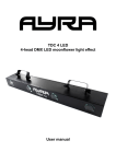
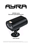
ComPar KIT 1 & 2
DMX LED light set with power outputs
User manual
Any information and illustrations shown in this user manual are subject to change without further notice.
User manual version: 2.0 Creation date + author initials: 30-07-2013 RV Revision date + author initials: 11-02-2014 RV
Introduction
Thank you for purchasing the Ayra ComPar Kit. You have either purchased the ComPar Kit 1 or ComPar Kit
2. This user manual is suitable for both products as the products are almost identical. The main difference is
the used LED light source.
Read this user manual before you set up the system, to become familiar with the product and its
accessories. Also check the box contents for possible damage or missing parts.
If you encounter any problems during use, contact your local dealer for more information and help.
The Ayra ComPar Kit is a versatile lighting system, used for entertainment purposes. It is an ideal system for
mobile DJ's, solo-entertainers and bands who wish to add colourful changing lights to their performance. This
will enhance the mood of your audience.
The ComPar Kit consists of a bar with four projectors mounted, each projector can be individually adjusted
and aimed. It is possible to cross beams, or make a fan shape of all projectors. The options are nearly
limitless.
Each ComPar Kit projector uses a RGB colour mix system. This gives every user the possibility to choose
between thousands of colour tones for each projector. Make use of the built-in features of the system, for
example the sound activated mode or the built-in colour presets. It is also possible to link multiple fixtures in
a master-slave mode. For advanced control, use the DMX mode to control the complete bar or every single
projector with a DMX controller.
The all new ComPar Kit series have built-in power outlets, to pass wall outlet power through to other lighting
effects. Combined with the ability to mount other (third-party) projectors directly onto the system, you are
able to create a unique light setup for almost every venue.
Any information and illustrations shown in this user manual are subject to change without further notice.
User manual version: 2.0 Creation date + author initials: 30-07-2013 RV Revision date + author initials: 11-02-2014 RV
Safety instructions
WARNING!
Always keep this device away from moisture and rain! Hazardous electrical shocks may occur!
WARNING!
Only connect this device to a matching power outlet. This device is intended to work on a
specified AC currency. Connecting this device to power outlets with other voltages may result in
permanent damage and possible hazardous situations, such as fire or electrical shocks!
WARNING!
Be careful with every operation of this device. Touching live wires inside and outside the unit
may cause hazardous electrical shocks!
This unit must be operated by, or under the supervision of an adult. This device is not suitable for children.
Every person involved with the installation, operation and maintenance of this device has to:
- Be qualified
- Follow the instructions of this manual
- Make sure there is no damage caused by transport. If the device seems damaged from the outside, do not
use it and contact your dealer for more information and consultation.
- To make sure the device maintains in perfect condition and for safe operation, it is necessary for the user to
follow the instructions and warning notes of this user manual.
- Damage caused by improper use or modifications to the device are not covered by warranty.
- This device does not have any user-serviceable parts inside. Servicing of this device needs to be done by
qualified technicians.
Important notes regarding safety and health:
- Never let the power cord come in contact with other cables. Handle the power cord and all connectors with
the mains with caution.
- Never remove any warning or informative labels from the unit
- The ground contact always needs to be connected. Do not cover or remove the ground contact.
- Never leave cables lying around
- Do not open the device and do not modify any hard- or software of this unit.
- Do not insert this object into air vents.
- Do not connect this device to a dimmerpack.
- Do not switch the system on and off frequently as this will reduce the lifespan of the device.
- Do not drive the inputs of the fixture with a signal larger than required to work at full performance.
- Only use this device indoor, avoid contact with water, moist or other liquids. Do not place items filled with
liquids on top of the unit.
Any information and illustrations shown in this user manual are subject to change without further notice.
User manual version: 2.0 Creation date + author initials: 30-07-2013 RV Revision date + author initials: 11-02-2014 RV
- Avoid nearby flames or heat sources, do not place this device near flammable liquids, gas or flammable
items.
- Always disconnect the device when it is not in use for a longer period or time, when servicing is needed or
when the device needs cleaning.
- Only handle the power cord by its connectors. Never pull the cable to remove a connector from its socket,
as this could lead to damage and electrical shocks.
- Always operate this device with a stable AC current.
- Always operate this device with the AC ground wire connected to the electrical system's ground.
- Never use other types of cables than specified in the manual, do not use defective or bad functioning
cables. Contact your dealer when the included or required cables do not work properly with this device.
- When the device has been exposed to large temperature differences (for example, transport from outdoor
to indoor), do not connect the device immediately. Do not activate the unit until it has reached room
temperature, as moist might build up inside the unit, which may cause shortcuts and/or electrical shocks.
Guidelines and types of use:
- This device is intended to be used by professionals on stage, in theaters, clubs and other equal venues.
- This device is not suitable for children and always needs to be operated by an adult.
- Only use the device when the environment is suitable and will not cause any damage. Do not use the
product in moist or dusty environments, or where long-term damage may occur such as:
- indoor swimming pools where chlorine is used.
- Beaches, where sand and salt are present.
- Outdoor, without roof protection
- Indoor areas where intense heat sources are present or where the temperature exceeds levels
which are comfortable for humans.
- Only use the included power adapter and only connect the device to a suitable power outlet with the correct
output voltage. Connecting the device to a power outlet with the wrong type of voltage or using the product
with a wrong type of power supply may cause permanent damage to the device.
- Avoid shocks and collision during use and transport. Do not transport the device while in use. Avoid brute
force during the installation and operation of this device.
- Familiarize yourself with the functions of the device before use. Do not allow operation of the device by
unskilled or unqualified people.
- Use of the device in other ways than described in this user manual may cause damage and injury. Ayra
does not take responsibility for any damage or injury caused by improper use.
Storage and transport:
- This device is intended for mobile use. When transported, use the original packaging of the product, or a
fitting flightcase, preferably filled with foam.
- This device is not intended for permanent use. Operation breaks will ensure that the lifespan of the device
remains unchanged.
- If the device is not used for a longer period of time, disconnect it from its power source and store it in its
original packaging, or in a fitting flightcase.
- Store the device indoor, dry and do not expose the device to extreme temperature differences.
Housing:
- Inspect the housing of the device frequently. Severe dents, cracks and missing screws should be avoided
at all costs. Do not use the device when the housing is not in optimal condition. Contact your dealer or a
skilled technician when in doubt about the state of the device
- Check the fixture and screws for corrosion. Corrosion should not be present on the fixture. Contact your
dealer or a skilled technician when corrosion is found on the fixture
- Every power or signal chassis/connector should be mounted tightly. Do not use the device when connectors
are loose.
- Do not use the power cord when the cores are visible. Contact your dealer for a replacement if needed.
- Avoid the buildup of dust and dirt. Clean the exterior of the fixture every month with a dry or damp cloth.
When using the device intensively, the cleaning frequency needs to be increased.
Any information and illustrations shown in this user manual are subject to change without further notice.
User manual version: 2.0 Creation date + author initials: 30-07-2013 RV Revision date + author initials: 11-02-2014 RV
Fuses:
- The main fuse of this device is to be found on the rear of the device. In most cases, directly next to the
power inlet.
- Only replace a fuse for a new one with the same type and rating! Do not use a fuse with a higher or lower
rating.
- Do not bridge the fuse with electrical wires, aluminum foil, as the fuse is used for protection against
electrical shocks and short circuit.
- Always mount the fuse cover back to the fuse compartment.
Any information and illustrations shown in this user manual are subject to change without further notice.
User manual version: 2.0 Creation date + author initials: 30-07-2013 RV Revision date + author initials: 11-02-2014 RV
Light effect guidelines
WARNING!
This lighting device is capable of suddenly producing concentrated light beams, which might
cause disorientation when looking directly into the optical systems on short distance. Do not
look directly into the optical lens from short distance.
WARNING!
This lighting device has a built-in strobe mode, which creates pulsating, bright beams. Do not
use this function continuously in a dark environment as this might cause disorientation.
Any information and illustrations shown in this user manual are subject to change without further notice.
User manual version: 2.0 Creation date + author initials: 30-07-2013 RV Revision date + author initials: 11-02-2014 RV
Box contents
Box contents
1x Ayra ComPar Kit 1 or 2
1x lighting stand
1x foot controller with connection cable
1x padded case for ComPar Kit 1 or 2
1x lighting stand bag
1x power cable (IEC – Schuko)
1x signal cable for foot controller (5P XLR – 5P XLR)
Unit and accessory inspection
- Always use the supplied power cable to connect the unit to a power supply. If the cable appears broken or
has visible damage, do not use it.
- If the unit is not going to be used for a longer period of time, disconnect it from the power supply and store it
in a dust-free environment.
- Always check the unit for possible damage before use. If you suspect that something is wrong with the unit,
do not connect it to a power source! When you suspect that your unit is broken or damaged, contact your
local dealer or a certified technician to inspect the unit.
Any information and illustrations shown in this user manual are subject to change without further notice.
User manual version: 2.0 Creation date + author initials: 30-07-2013 RV Revision date + author initials: 11-02-2014 RV
Device overview
2
2
2
2
3
1
4
1
1
1
5
6
7
8
9
1. Beam output
2. Tightening knob (for hooks, light effect mounting, etc.)
3. Stand mounting adapter with tightening knobs, for placement on the included standard
4. Double braced lighting stand with extension tube, safety pin and tightening knobs
5. Storage and transport bag for ComPar Kit fixture, foot controller and cables
6. Foot controller
7. Suspend button (blackout)
8. Menu button (select working mode)
9. Up button (select colour or show)
10. Full button (Full output white blinder fade function)
Any information and illustrations shown in this user manual are subject to change without further notice.
User manual version: 2.0 Creation date + author initials: 30-07-2013 RV Revision date + author initials: 11-02-2014 RV
10
12
11
14
15
16
17
18
19
13
11
11. AC power output 110-230V AC, 50/60 Hz (to power other lighting fixtures during use on a stand or in a
truss construction)
12. LED display with menu buttons
13. ComPar Kit fuse (fuse for the ComPar Kit itself)
14. AC power input 110-230V AC, 50/60 Hz (to power the fixture and if connected, other lighting fixtures
15. Power output fuse (fuse for the ComPar Kit power outputs)
16. DMX input with 3P XLR
17. DMX output with 3P XLR
18. Foot connector connector, 5P XLR
19. Built-in microphone for sound activated mode
Important notice!
Power inputs & outputs
The ComPar Kit fixtures have independent fuses for the bar itself and the power outputs. They
are directly connected to the AC power input which they share. The internal wiring of the fixture
is built to withstand a load of 16A max. total.
The ComPar Kit fixture electronics are equipped with a F3A 20mm fuse.
The Power outputs are equipped with a F7A 20mm main fuse, which bears the total load for the
power outputs. Every power output is capable of being loaded with 7A max., but the combined
load for both output can not exceed 7A. Doing so will result in blowing the internal fuse. Even
though the bar may withstand a larger load, the 7A fuse is chosen for safety reasons. No
problems will occur when connecting one, two or several LED lighting fixtures. Connecting
fixtures with a high power consumption (such as fog machines) is not recommended by Ayra.
Any load greater than 16A total on the power outputs will also cause the 7A fuse to blow. But in
addition to that, chances are high that the circuit breaker of your power circuit may also cut the
power, causing other fixtures connected to the circuit to deactivate due to the loss of power.
The fuses inside the ComPar Kit act independent of each other. Therefore, any power issues with
connected lighting fixtures that cause the output fuse to blow, will not result in problems for the
bar itself, so it will keep running and prevent total blackout.
Fuses and ratings are identical for the ComPar Kit 1 and 2. This means that it is theoretically
possible to connect a total of 20 ComPar Kit fixtures in a single line, without power problems (As
the maximum power capacity of the power outputs combined is 1610W).
Any information and illustrations shown in this user manual are subject to change without further notice.
User manual version: 2.0 Creation date + author initials: 30-07-2013 RV Revision date + author initials: 11-02-2014 RV
Setting up the unit
The ComPar KIT series comes with a practical lighting tripod stand. Extract the feet of the stands until they
are fully extended. Pull the distance tube out until you reach a proper install height and tighten the knob. Use
the included safety pin to ensure that the stand will not be able to slide down. Place the ComPar KIT bar on
the stand. To activate the unit, connect the included power supply to the unit and a suitable 230V, 50 Hz
power outlet. The unit will activate directly after it is plugged in to a wall outlet or other power source.
The status of the fixture is shown on the display. Certain values determine the current status and will change
when you push buttons on the control panel. The buttons each have their own function, for easy navigation in
the control panel.
Display codes:
display
Mode
ADDR
DMX address setting
Function
A001-A512
CHND
Channel mode
1 channel mode
3 channel mode
7 channel mode
12 channel mode
16 channel mode
SLND
Slave mode
Slave 1, Slave 2
SHND
Show mode
Show 1 - Show 8
SOUN
Sound mode
Sound on/off
SENE
Sound sense
Sound sense 0-100
BLND
Black out mode
LED mode, YES – NO
DISP
Display inversion
Display Inversion,Idsp-dspI
TEST
Test mode
Self test
Hour
Using time of light
Fixture hours,0 ~ 9999
Description
Set the DMX start address
by choosing a value
between 1 and 512.
Select the DMX channel
mode, which will determine
how many channels the unit
will fill on your DMX
controller. More channels =
more specific functionality
NOTE: Only possible by
connecting two ComPar KIT
units with each other by 3p
XLR cable.
Set the unit to Slave 1 (sync)
or Slave 2 (mirrored) mode
Select any internal automatic
show for stand-alone
applications
Activate or deactivate the
internal microphone and the
music-controlled mode
Select the sensitivity of the
internal microphone, for the
sound-active mode
Activates or deactivates the
beam output for the LED
projectors
Inverts the display, when the
unit is used upside-down as
large floorspot with floor
stands. This makes it easier
to read certain display
statuses.
Self-test program, projects
all colours separately. This
makes it possible to check if
there are defect LED
modules.
Displays the run time of the
fixture. Used by rental
companies to determine
Any information and illustrations shown in this user manual are subject to change without further notice.
User manual version: 2.0 Creation date + author initials: 30-07-2013 RV Revision date + author initials: 11-02-2014 RV
UERS
version
Software version,Ver XXX
service/maintenance
intervals.
Firmware software version,
not upgradeable by users
Foot controller features:
Blackout
Blackout the unit
1.
2.
3.
Strobe
Synchronous strobe in white
Sound strobe in white
Sound strobe in color
Function
Mode
Sound (LED OFF)
-
Select color
Red
Green
Blue
Red + Green
Red + Blue
Green + Blue
Red + Green + Blue
Color
change
by
sound
Manual Color (LED ON)
Select Show
1–8
Show (LED slow blinking)
Working modes:
Stand-alone (automatic): Select one of the internal programs, which will activate and run in a continuous
loop.
Music controlled mode (sound-active): Activate the internal microphone by using the display and set the
right sensitivity for optimal music-controlled shows. Select one of the predefined shows. The show will
change step by step when sound is detected.
Master/slave mode (sync-mode): Connect two or multiple ComPar KIT systems with a standard 3p male to
3p female XLR cable. The first system will act as a master fixture, the second system will mimic the actions
of the first system, thus creating synchronized effects.
To ensure that this function works properly, use the DMX OUT connector of the first system and the DMX IN
connector of the second system. Set the second system to Slave 1 or Slave 2 mode (synchronized or
mirrored mode). Connecting more than 1 slave is possible, with a maximum of 16 units.
The Master/slave mode also works when using the included foot controller. Connect the foot controller to the
first fixture with the 5P connector, then feed the signal through from fixture to fixture with the DMX in- and
outputs.
DMX mode: The most extended working mode, as this function gives you the ability to control the system
with a standard DMX-512 controller, using the 3p DMX in- and outputs. Select one of the several channel
modes and set the right starting address. After this, you have full control over the system with your DMX
controller.
This unit has the following DMX-channels and DMX-values:
1 Channel Mode
CH1
Chase
000-007 Blackout
008-037 Show 01
038-067 Show 02
068-097 Show 03
098-127 Show 04
128-157 Show 05
Any information and illustrations shown in this user manual are subject to change without further notice.
User manual version: 2.0 Creation date + author initials: 30-07-2013 RV Revision date + author initials: 11-02-2014 RV
158-187 Show 06
188-217 Show 07
218-247 Show 08
248-255 Random Show 01-08
3 Channel Mode
CH1
CH2
CH3
7 Channel Mode
CH1
CH2
CH3
CH4
CH5
Red
Green
Blue
000-255 Dimmer 0-100%
000-255 Dimmer 0-100%
000-255 Dimmer 0-100%
Red
Green
Blue
Dimmer
000-255 Dimmer 0-100%
000-255 Dimmer 0-100%
000-255 Dimmer 0-100%
000-255 Dimmer 0-100%
000-007 No function
008-247 Strobe slow to fast
248-255 Sound strobe
000-007 Manual
008-022 Color chase 1
023-037 Color chase 2
038-052 Color chase 3
053-067 Color chase 4
068-082 Color chase 5
083-097 Color chase 6
098-112 Color chase 7
113-127 Color chase 8
128-142 Color chase 9
143-157 Color chase 10
158-172 Color chase 11
173-187 Color chase 12
188-202 Color chase 13
203-217 Color chase 14
218-232 Color chase 15
233-247 Color chase 16
248-255 Stand alone
000-007 Hold
008-255 Speed slow to fast
Strobe
CH6
Color chase
CH7
12Channel Mode
CH1
CH2
CH3
CH4
CH5
CH6
CH7
CH8
CH9
CH10
CH11
CH12
Speed
Red 1
Green 1
Blue 1
Red 2
Green 2
Blue 2
Red 3
Green 3
Blue 3
Red 4
Green 4
Blue 4
000-255 Dimmer 0-100%
000-255 Dimmer 0-100%
000-255 Dimmer 0-100%
000-255 Dimmer 0-100%
000-255 Dimmer 0-100%
000-255 Dimmer 0-100%
000-255 Dimmer 0-100%
000-255 Dimmer 0-100%
000-255 Dimmer 0-100%
000-255 Dimmer 0-100%
000-255 Dimmer 0-100%
000-255 Dimmer 0-100%
Any information and illustrations shown in this user manual are subject to change without further notice.
User manual version: 2.0 Creation date + author initials: 30-07-2013 RV Revision date + author initials: 11-02-2014 RV
16 Channel Mode
CH1
CH2
CH3
CH4
CH5
CH6
CH7
CH8
CH9
CH10
CH11
CH12
CH13
CH14
Red 1
Green 1
Blue 1
Red 2
Green 2
Blue 2
Red 3
Green 3
Blue 3
Red 4
Green 4
Blue 4
Dimmer
Strobe
CH15
Color chase
CH16
Speed
000-255 Dimmer 0-100%
000-255 Dimmer 0-100%
000-255 Dimmer 0-100%
000-255 Dimmer 0-100%
000-255 Dimmer 0-100%
000-255 Dimmer 0-100%
000-255 Dimmer 0-100%
000-255 Dimmer 0-100%
000-255 Dimmer 0-100%
000-255 Dimmer 0-100%
000-255 Dimmer 0-100%
000-255 Dimmer 0-100%
000-255 Dimmer 0-100%
000-007 No function
008-247 Strobe slow to fast
248-255 Sound strobe
000-007 Manual
008-022 Color chase 1
023-037 Color chase 2
038-052 Color chase 3
053-067 Color chase 4
068-082 Color chase 5
083-097 Color chase 6
098-112 Color chase 7
113-127 Color chase 8
128-142 Color chase 9
143-157 Color chase 10
158-172 Color chase 11
173-187 Color chase 12
188-202 Color chase 13
203-217 Color chase 14
218-232 Color chase 15
233-247 Color chase 16
248-255 Stand alone
000-007 Hold
008-255 Speed slow to fast
Any information and illustrations shown in this user manual are subject to change without further notice.
User manual version: 2.0 Creation date + author initials: 30-07-2013 RV Revision date + author initials: 11-02-2014 RV
Installation and maintenance
Installing the system in a standing position (right side up)
The ComPar KIT 1 and 2 are equipped with a 35 mm stand adapter, which
makes it possible to position the system on a standard loudspeaker or
lighting stand. A screw knob is attached to the adapter, used to tighten the
system so it is unable to turn around. This also prevents unwanted rattle
noise caused by speaker vibrations, and possible instability as tube
diameters of stands may always vary slightly.
Installing the fixture in a standing position (inverted)
It is possible to use the LED projectors as a floor spot system, for example
when you want to use them for uplighting purposes. For this feature, use the
screw knobs at the top of the system and mount a floor stand on each side (floor
stand not included). Invert the display status by using the menu option, for easy
reading of values. After this, flip the system and position the bar as you wish.
NOTE: You may need to replace the screw knobs for standard bolts, as the
height of floor stands may vary.
Installing the fixture in a hanging position
When installing the system in a hanging position (for example, on a truss
construction), detach the screw knobs and install proper G-clamps or half couplers (not included).
NOTE: When installing the system in a hanging position, the following list of safety precautions must be met:
- Use at least two hanging points (clamps), for optimal stability and safety.
- Use at least one (recommended amount: 2) safety cable(s), capable of holding 3x the weight of the system.
Safety cables must be installed in such a way that it is impossible for the system to fall down when one of the
two mounting points breaks.
- It is prohibited to install the system by using only safety cables or chains!
Warranty is void when any of the above safety precautions are not met. Ayra can not be held responsible if
any damage or injury occurs due to improper use of the system.
Transport
When using this fixture in mobile setups, provide sufficient protection during transport. Always use the
provided transport bags to protect the system and included lighting stand.
Replacing the internal fuses
First check whether a failing power supply may be the cause of malfunction. When you suspect that one of
the internal fuses is broken, the fuse can be replaced by removing the fuse cover, located on the rear of the
fixture, near the power inputs, outputs and control menu.
WARNING: Before checking the fuse, always disconnect the fixture from your wall outlet or any other power
supply to prevent electric shocks.
Always replace a broken fuse with a fuse that has the same type and rating. After the fuse has been
replaced, always close the fuse-cover. Reconnect the fixture to your power supply and check whether the
problem is solved. When this does not solve your problem, contact your local dealer for help.
Spare parts
This unit has no user serviceable parts inside. When any damage to internal components occurs, contact
your local dealer or a specialized technician in order to repair the fixture.
Cleaning:
Clean the housing of the fixture frequently with a damp cloth, to remove dust and/or dirt.
WARNING: Always disconnect the fixture from your wall outlet or other power supply and let the fixture dry
before reconnecting it. This prevents possible electrical shocks.
Any information and illustrations shown in this user manual are subject to change without further notice.
User manual version: 2.0 Creation date + author initials: 30-07-2013 RV Revision date + author initials: 11-02-2014 RV
The lenses can be cleaned with a non-aggressive glass cleaning solution, but is not recommended. Ayra
recommends to clean the mirror and lens with a fine brush, while removing dust and/or dirt with a vacuum
cleaner. Avoid touching the lenses with your bare fingers, to prevent fingerprints on the optics.
Checkup
To prevent dangerous situations, make sure your fixture is in optimal condition before using it. Check your
fixture frequently by using the following checklist:
- All screws must be mounted tightly.
- Check all screws and metal parts for corrosion. No visible corrosion may be present.
- The exterior of your fixture must be in optimal condition. Check your fixture for dents, cracks or missing
parts.
- Your installation spot must be in optimal condition. Check your installation spot for corrosion, cracks, dents
and strength.
- Electrical components (connectors and cables) must be in optimal condition. Any form of damage (cuts,
exposed wire cores or any other visual deformities should not be present.
If any visual or mechanical damage is detected, contact your local dealer or a specialized technician. Do not
use a damaged or failing fixture.
Connectors and wiring schematics:
DMX-connections:
Electrical wiring:
Any information and illustrations shown in this user manual are subject to change without further notice.
User manual version: 2.0 Creation date + author initials: 30-07-2013 RV Revision date + author initials: 11-02-2014 RV
DMX lighting troubleshooting
If you have any problems with DMX lighting, consult this troubleshooting section to solve any difficulties with
your product. If this troubleshooting section does not solve your problem, contact your dealer for more
information and help.
This troubleshooting section contains the most frequent problems and is not a complete collection of possible
faults, defects and solutions. The troubleshooting section applies for DMX controllers, DMX cabling and DMX
lighting fixtures. It is possible that not all described problems, causes and solutions apply to your situation as
product details may vary from product to product.
Problem
Possible Cause
Solution
The fixture does not activate itself
Blown fuse
Check the fuse compartiment for
blown fuses and replace it if
necessary.
No power cable plugged in
Plug in the power supply to a
matching power outlet
Power switch is not in the ON
position
Turn on the device by switching
the ON/OFF switch to the ON
position, if available
Wrong DMX address
Set the DMX address to the right
value
DMX controller blackout function
activated
Deactivate the blackout function of
your DMX controller
Faulty positioning of the DMX
polarity switch on the controller
flip the polarity switch on your
DMX controller
No response or DMX activity
signal LEDs active
Check your DMX cables for
possible connection breaks and
replace them if necessary.
Wrong working mode selected.
Check if the sound activated mode
of the fixture is activated.
Microphone sensitivity level is set
too low
Increase the microphone
sensitivity of the built-in
microphone
Speaker placed too far away or
lack of bass
Place your lighting effect closer to
your speakers (or vice versa)
and/or increase low frequency
volumes. The microphone will not
be triggered with high pitched
sounds.
Dirty/dusty optics
Clean the lens and/or other optics
with a dry or damp cloth
Dimmer is not set to full output
Set all dimmer levels to 100% on
your DMX console
Faulty/broken DMX cables
Check your DMX cables for
possible connection breaks and
replace them if necessary.
Power cable interference on your
Avoid installing the DMX and
The fixture does not respond to
DMX signals
The fixture does not respond to
sound
The beam output is very low
Sometimes the DMX signal is lost
and/or some fixtures are
flickering / behaving odd
sometimes
Any information and illustrations shown in this user manual are subject to change without further notice.
User manual version: 2.0 Creation date + author initials: 30-07-2013 RV Revision date + author initials: 11-02-2014 RV
DMX signal
(high) power cables parallel to
each other.
No DMX terminator
Apply a DMX terminator at the end
of your DMX-chain
Signal loss or distortion in DMX
values
Apply a DMX booster in your DMX
chain after 32 fixtures or less. After
a maximum of 32 fixtures the DMX
signal needs to be refreshed.
Moving parts are not functioning
well, values do not match and/or
rattling sounds are noticed
Faulty stepping motor positioning
Possible value loss of stepping
motors. Activate the reset function,
or unplug the power supply and
plug it back in to activate the reset
program. This will reset all values
to the original 0-point.
The fixture does not respond fast
enough to the set speed on my
DMX controller
Moving parts can not keep up with Decrease the chase speed of your
the set speed
DMX controller, as the stepping
motors of your fixture need some
time to move from one point to
another.
The fixture does not respond to all Wrong DMX channel mode
DMX-channels
Check the DMX channel mode of
the fixture. If the wrong value is
set, change the channel mode to a
different setting and try again.
Any information and illustrations shown in this user manual are subject to change without further notice.
User manual version: 2.0 Creation date + author initials: 30-07-2013 RV Revision date + author initials: 11-02-2014 RV
Technical specifications
-
Compact lighting system
Equipped with four projectors
Projectors individually adjustable
Colourful light effects thanks to RGB LED light source
Automatic, sound active, master-slave and DMX working modes
Two selectable ‘Slave’ modes
Microphone sensitivity digitally adjustable for sound active mode
Several DMX channel modes (1, 3, 7, 12 or 16 channels)
LED-display with menu buttons
Display invert
IEC power inlet
Screw knobs at the top
Integrated stand adapter with screw knob
Included foot control, for easy light show control by musicians and DJ’s
Included lighting stand, for easy plug-and-play setups
Included transport bag for the system + lighting stand for optimal safety and convenience during
transport and storage
Power requirements: 110 – 230V AC, 50/60 Hz
Power consumption: 80W
Two power outputs, suitable for powering other ComPar kits, ComPar fixtures or (LED) lighting
fixtures
ComPar Kit fuse: F3A, 20 mm glass
Power outputs fuse: F7A, 20 mm glass
Total weight: 10.5 kg
LED Light source:
- ComPar KIT 1: 145x 10mm LED (49R,48G,48B) for each projector (50.000h estimated lifespan)
- ComPar KIT 2: 7x 9W Tri-Color RGB LED modules for each projector (50.000h estimated lifespan)
Projector features:
- Four separate projectors on each system
- equipped with ventilation slots for optimal cooling and long lifespan
- wide angle manual pan and tilt for each projector individually, for optimal beam adjustment
- solid cable from every projector to the main bar
Connectors:
- DMX: 3p XLR male and female
- Power: IEC power connector
- Foot controller: 5p XLR
Included accessories:
1x lighting stand (max. height 2.8m)
1x foot controller with connection cable
1x padded case for ComPar Kit 1 or 2
1x lighting stand case
1x power cable (IEC – Schuko)
1x signal cable for foot controller (5P XLR – 5P XLR)
Any information and illustrations shown in this user manual are subject to change without further notice.
User manual version: 2.0 Creation date + author initials: 30-07-2013 RV Revision date + author initials: 11-02-2014 RV