1
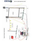
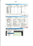
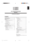
72× 40mm () 4R - 10 USER MANUAL Table of content 1.Ooen the box and checking┄┄┄┄┄┄┄┄┄┄┄┄┄┄ 1 2.Safety instructions┄┄┄┄┄┄┄┄┄┄┄┄┄┄┄┄┄┄ 1 3.Operatingdeterminations┄┄┄┄┄┄┄┄┄┄┄┄┄┄┄ 2 4.Rigging the fixture┄┄┄┄┄┄┄┄┄┄┄┄┄┄┄┄┄┄ 3 5.Description of the device┄┄┄┄┄┄┄┄┄┄┄┄┄┄┄ 5 6.Dimension┄┄┄┄┄┄┄┄┄┄┄┄┄┄┄┄┄┄┄┄┄┄ 6 7.DMX-512 connection┄┄┄┄┄┄┄┄┄┄┄┄┄┄┄┄┄ 7 8.DMX protocol ┄┄┄┄┄┄┄┄┄┄┄┄┄┄┄┄┄┄┄┄ 8 9. Control menu map ┄┄┄┄┄┄┄┄┄┄┄┄┄┄┄┄┄┄ 14 10.Error and information messages┄┄┄┄┄┄┄┄┄┄┄┄ 18 11.Technical specifications┄┄┄┄┄┄┄┄┄┄┄┄┄┄┄┄ 22 12. Maintenance and cleaning┄┄┄┄┄┄┄┄┄┄┄┄┄┄┄ 25 1. Open the box and checking Congratulations on choosing our products! Please carefully read this instruction m anual in its entirety and keep it well for using reference. This m anual contained about the installation and the relative using information of this products. Please according to this m anual's relative speaking when using this equipm ent. This equipm ent was made of new style, high intensity plastic . It fully shows the m odem times light characteristic with beauty structure. And it was made according to CE standard. Fully up the international standard of DM X512 agreem ent. M aster or slave in phase control.Can be use in large entertainm ent, theater, performing and playing hall, etc. This product uses Philips MSR Gol d 1200 F ast F IT ,750 ho u rs . When receiving this product please carefully bring and put; and check that whether this equipm ent has been dam aged or not during transportation. And please also check the following thing was enclosed: Signal line ------------------- one piece User M anual ------------------ one set Safety string ------------------one piece 2. Safety instructions Every person involved with installation and maintenance of this device have to: - be qualilfied - follow the instructions of this manual CAUTION! Be careful with your operations. With a high voltage you can suffer a dangerous electric shock when touching the wires! This device has left our premises in absolutely perfect condition. In order to maintain this condition and to en-sure a safe operation, it is absolutely necessary for the user to follow the safety instructions and warning notes written in this manual. Important: ◆The manufacturer will not accept liability for any resulting damages caused by the non-observance of this manual or any unauthorized modification to the device. ◆Please consider that damages caused by manual modifications to the device are not subject to warranty. ◆Never let the power-cord come into contact with other cables! Handle the power cord and all connections with the mains with particular caution! ◆Make sure that the available voltage is not higher than stated on the rear panel. ◆Always plug in the power plug least. Make sure that the power-switch is set to off-position before you connect the device to the mains. The power plug has to be accessable after installing the device. ◆Make sure that the power-cord is never crimped or damaged by sharp edges. Check the device and the power-cord from time to time. .1. ◆Always disconnect from the mains, when the device is not in use or before cleaning it. ◆Only handle the power-cord by the plug. Never pull out the plug by tugging the power cord. ◆ This device falls under protection class I. Therefore it is essential to connect the yellow/green conductor to earth. ◆ The electric connection, repairs and servicing must be carried out by a qualified employee. ◆Do not connect this device to a dimmer pack. ◆Do not switch the fixture on and off in short intervals as this would reduce the lamp’s life. ◆During the initial start-up some smoke or smell may arise. This is a normal process and does not necessarily mean that the device is defective. ◆Do not touch the device’s housing bare hands during its operation (housing becomes hot)! ◆For replacement use lamps and fuses of same type and rating only. CAUTION ! EYEDAMAGES ! Avoid looking directly into the light source (meant especially for epileptics) ! 3. Operating determinations ◆This device is a moving-head for creating decorative effects and was designed for indoor use only. ◆ If the device has been exposed to drastic temperature fluctuation (e.g. after transportation), do not switch it on immediately. The arising condensation water might damage your device. Leave the device switched off until it has reached room temperature. ◆Never run the device without lamp! ◆Do not shake the device. Avoid brute force when installing or operating the device. ◆Never lift the fixture by holding it at the projector-head, as the mechanics may be damaged. Always hold the fixture at the transport handles. ◆When choosing the installation-spot, please make sure that the device is not exposed to heat, moisture or dust. There should not be any cables lying around. You endanger your own and the safety of others! ◆The minimum distance between light output and the illuminated surface must be more than 1.5 meters. ◆Make sure that the area below the installation place is blocked when rigging, derigging or servicing the fix-ture. ◆Always fix the fixture with an appropriate safety rope. Fix the safety rope at the correct holes only. ◆operate the fixture after having checked that the housing is firmly closed and all screws are tightly fas-tened. ◆The lamp must never be ignited if the objective-lens or any housing-cover is open, as discharge lamps may explose and emit a high ultraviolet radiation, which may cause burns. .2. ◆The maximum ambient temperature 40°C must never be exceeded. ◆Operate the device only after having familiarized with its functions. Do not permit operation by persons not qualified for operating the device. Most damages are the result of unprofessional operation! ◆Please use the original packaging if the device is to be transported. ◆Please consider that unauthorized modifications on the device are forbidden due to safety reasons! ◆If this device will be operated in any way different to the one described in this manual, the product may suffer damages and the guarantee becomes void. Furthermore, any other operation may lead to dangers like short-circuit, burns, electric shock, burns due to ultraviolet radiation, lamp explosion, crash etc. The lamp used in this projector is a discharge lamp.After switching off don't attempt to restart the projector until la mp has cooled,this will require approx 15 minutes.Switc hing the lamp on and off at short intervals will reduce the life of both the lamp and the projector.But occasional bre aks will prolong the lamp and projector. 4.Rigging the fixture DANG ER TO LIFE Please consider the respective national norm s during the Installation! The installation must only be carried out by an authorized dealer! Ø The installation of the projector has to be built and constructed in a way that it can hold 10 times the weight for 1 hour without any harming deformation. Ø The installation must always be secured with a secondary safety attachment, e.g. An appropriate catch net. This secondary safety attachment must be constructed in a way that no part of the installation can fall n if the main attachment fails. ØW hen rigging, derigging or servicing the fixture staying in the area below the installation place, on bridges, under high working places and other endangered areas is forbidden. Ø The operator has to make sure that safety-relating and machine-technical installations are approved by an expert before taking into operation for the first time and after changes before taking into operation another time. .3. Ø The operator has to make sure that safety-relating and machine-technical installations are approved by an expert after every four year in the course of an acceptance test. Ø The operator has to make sure that safety-relating and machine-technical installations are approved by a skilled person once a year. Ø The projector should be installed outside areas where persons m ay walk by or be seated. Ø IM PO R TA N T! OVERHEAD RIGGING REQUIRES EX TEN SIV E EX PERIEN CE, including (but not limited to)calculating working load limits, installation material being used, and periodic safety inspection of all installation material and the projector. If you lack these qualifications, do not attempt the installation yourself, but instead use a professional structural rigger. Improper installation can result in bodily injury and or damage to property. Ø The projector has to be installed out of the reach of people. Ø If the projector shall be lowered from the ceiling or high joists, professional trussing system s have to be used. The projector must never be fixed swinging freely in the room . Ø Caution Projectors may cause severe injuries when crashing down! If you have doubts concerning the safety of a possible installation, do NOT install the projector! Ø Before rigging make sure that the installation area can hold a minim um point load of 10 times the projector s weight. Ø The projector can be placed directly on the stage floor or rigged in any orientation on a truss without altering its operation characteristics. Ø For overhead use, always install a safety-rope that can hold at least 10 times the weight of the fixture. You must only use safety-ropes with screw –on carabines. Pull the safety-rope through the two apertures on the bottom of the base and over the trussing system etc. Insert the end in the carabine and tighten the fixation screw . .4. 5.Description of the device 1. power switch 2. Insurance seat 3. power-in 4. Insurance seat 5. 3-pin XLR female 6. 3-pin XLR male 7. 5-pin XLR male 8. 5-pin XLR female 1 2 1.LED 2.UP 3.DOWN 3 .5. 6. Dimension .6. 7.DMX-512 connection If you wish to change the power supply settings, see the chapter Appendix. Connect the fixture to the mains with the enclosed power cable and plug. The earth has to be connected! Cable(UE) Cable(US)-208V Pin International Brown Black Live L Liht blue white Neutral N Yellow/Green Green Earth DM X-512 connection/connection between fixtures Only use a stereo shielded cable and 3-pin XLR-plugs and connectors in order to connect the controller with the fixture or one fixture with another. DMX-OUTPUT ~ ~ DMX512 DMX-INPUT 3 3 2 1 1 2 Caution: A t the last fixture, the DM X-cable has to be terminated with a terminator. Solder a 120 resistor between Signal (-) and Signal (+) into a 3-pin XLR-plug and plug it in the DMX-output of the last fixture. ~ 5å ( ) Pin 1:GND(SCREEN) Pin 2:Signal(-) Pin 3:signal(+) Pin 4:N/C Pin 5:N/C ~ 3å ( ) Pin 1:GND(SCREEN) Pin 2:Signal(-) Pin 3:signal(+) .7. 3å (N) Pin 1:GND(SCREEN) Pin 2:Signal(-) Pin 3:signal(+) 5å (N) Pin 1:GND(SCREEN) Pin 2:Signal(-) Pin 3:signal(+) Pin 4:N/C Pin 5:N/C 8、Colorsp o t 1 2 0 0 E F - D M X P R O T O C O L .8. .9. .10. .11. .12. .13. 9.Control menu map Def ault settings=Bold print Def ault settings=Bol d pri nt Fixture Address DMX Address 001 : 512 Eth ernet s ettin gs S et e the r ne t Mod e Disable Etherne Ethernet Et h er net /DMX S et I P A ddr ess Default IP Address C ust o m IP Adr ess S e t Ar t Ne t Uni ve rse (0-255): Fix urte information Powe r On Time Tot a l Ho ur s Re s et ab le ho u rs Lam p On time To ta l Hou rs: Reset able Ho u rs: Lam p Strik es: To tal S tr ik es: Rese st a ble St rk es Air filter s Se t A le rt p e riod( 10 ...50 ... 300 ho ur s ) Elapse d tim e[hour s] F ix ture Te mpe r atu res Cu rr ent: Am b ie nt T emp .[℃] Bo a rd T emp .[℃] H ea d T em p.[℃] Maximum N o n re set a b le: Am b ient T e mp. [℃]: Bo ard Te mp. [℃] Hea d T emp. [℃] Ma ximum R ese ta bl e: Am bie nt T emp .[℃]: Bo a rd T em p .[℃] H ea d Tem p.[℃] DMX Values 001 512 Softwar e V e rsion I C1 M B I C2 M B Produ ct Id s IC 1 DS I C 2 DS M ac A dr RDM UID .14. Personality User Mode User User Us e r DMX P resetting: Mo de A Se ttin gs B Settin gs C Se ttin gs 1: Ch .1 P an : Ch .36 Dimm er F in e S et Acti v e: Mod e 2: Ch .1 P an : Ch .28 Dimm e r Set Acti ve: Mode 3: Ch .1 P an : Ch .34 Dimm er S et Acti v e: Mo de 4: Ch .1 P an : Ch .26 Dimm er Se t Acti v e: Mode 5: Ch .1 Sh utte r/ St rob e: : Ch . 31 S pec ia l fun cti ons Se t Acti v e: Pan Re vers e(On,Off ) Tilt Reve rse (On, Off ): Lam p P r ese tting La m p On/P ow er On ( On , Off) La mp Off via DMX (On ,O FF ) La mp On if DMX P res ent (On , Off Lam p Off if n o t DMX (On ,Off ): La mp leniti on de la y( 0 .. 1 .. 90)s Lamp Low Pow e r del ay( 10 s -600 s Gr een E ne r gy mod e (On , Off ): L amp Lig ht Se nsor( On ,Off Display Adjusti ng:LCD Dis play Per ma nent On (On ,Off ): Dis pla y Int ensit y( 1.. 10): Dis pla y Ba ckli g ht( 1.. 5.. 10): Di sp lay Turn ed( On , Off ): B la ckout d.M.C(On ,Off Pan / Tilt F eedba ck( On ,Off ): Mi crophone Se ns iti vity( 1 .. 10 .. 20): Fan M odes: At uo coo lin g Hi g h Coo lin g Pan /Tilt mode( Tim e m ode, S pee d M od e) Active Bla ckout Wh ile: Pan /Tilt M ovin g( On , Off ) Color Wh ee ls M ov in g(On , Off ): Gobo Wh eels M ov in g (On ,Off): Dimmer C urve (C urv e 1 ,Cu rv e 2 ) IR Sensor(On, Of f): Init Effec t Positi ons Pan (0-225) .15. : Dimmer(0-255) Dimmer fi ne ( 0-255): Save Tempera ture Unit(℃, F) Default Setting: La mp On/Off ( On, Off) o Test seq ue nces M ode 1: Pan( 0-255 ) Tilt(0-25 5) Zoom (0-255) Run Test P ro g r am Mode 2: Manu al Mode P re set Effcet Control Pan( Positio n 1,... ,P ositi on 7) : Dimmer(P ositi on 1,... ,P o siti o n 6): M a nual Effec t Control Pan( 0-255) : Dimmer Fin e ( 0-255): Stand-alone se ttin Music Tr igger(On,Off): P res etting Play b ack Disa bled Test prog r a m Prog ram 1 Prog ra m 2 Prog ram 3 Pl a ying P rogram T est Progra m I n Loop Prog ram 1 In Loop Prog ram 2 In Loop Program 3 In Loop E diting P rog r am: Progr am 1 Progra m 2 Progr am 3 E d it St ep s St ep 1 : St e p 99 Pa n(0-255) : Dimm er fine( 0-255): St e p Time (0 . 1-25 .5 s): S a ve Sa ve and copy: St ar t S tep( 1-99): End St e p( 1-99): .16. R es et functio n Rese t All Pan /Tilt : Zoom re set Sp ec ial functions Lamp Adjustment Pan( 0-255) Tilt( 0-255): Zoom ( 0-255) Effect A djustment: DMX V alu es Pa n (0-255) : Dimm e r fin e( 0-255): C alibr at e Va lue s Co lour W hee l(0-255): : Me ch .d imm e r 2(0-255) S ave and Res et Lo a d D efa ult Va lu e s: Upda ting Softwa re: .17. 10 Error and information messages Occured errors during fixture operation are signaled by warning icon on the display: Press [ESC] to see the current error messages. Description of error messages: Active Lamp Timer This message appears if you try to switch on the lamp within 5 minutes after having switched it off (the lamp is too hot). The message will appear on the display if the lamp doesn’t ignite within 28 seconds. The ColorSpot 700E AT will store this information and automatically ignite the lamp when the 5 minutes period has expired. Caution: The message is disabled if the lamp light sensor (function “Lamp Sensor”in menu Personality) is switched Off. Lamp Error The ignition of the lamp is seven times unsuccessful (the “Active Lamp Timer” message appeared six times before), and the display shows “Lamp Error”, meaning that the lamp could be damaged or even missed or there could be a failure on the ignitor or ballast. Please place or replace the lamp and contact your dealer if the situation was not caused by the lamp. Caution: The message is disabled if the lamp light sensor (function “Lamp Sensor” in menu Personality) is switched off. Lamp Sensor Error This message informs the lamp light sensor is failed. Caution: The message is disabled if the lamp sensor (function Lamp Sensor in menu Personality) is switched Off. Overheated-Lamp Off This message informs that the fixture head had been overheated and the lamp was switched off by head temperature sensor. Overheated-Lamp Low This message informs that the fixture head has been overheated and the lamp power is reduced. Short Power Error This message will appear if the fixture was shortly disconnect from the main. Supply Frequency Error This message will appear if the frequency of the main is not standard 50 or 60 Hz.This message can appear as a result of the interference during the lamp starting (if the lamp or igniter is old) or as a result of the interference by neighbouring devices. In these cases the message does not affect the fixture operating! .18. Temper.Sensor Error The message informs you that the communication betwen the head and the main board in the fixture base was cut off (or the head temperature sensor is defective) and the lamp was automatically switched off. Power down mode This message will appear if the fixture is switched to the "Power down mode" (e.g. fixture head is overheated). The following error messages are separated into 2 groups: xxxx xxxx Error 1 (e.g.Colour Wheel Error 1 ) xxxx xxxx Error 2 (e.g.Colour Wheel Error 2 ) There are some possible reasons of faults: Characteristic fault Message xxxx xxxx Error 1 Magnetic sensor is permanently On (e.g. leading wire is shortcirculated,defective stepping motor, defective control circuit on the PCB) xxxx xxxx Error 1/xxxx xxxx Error 2 Magnetic sensor is permanently Off(e.g.leading wire is disconnected, defective magnetic sensor,missing magnet),defective stepping motor Colour Wheel Error 1 (Colour Error 2 ) The messsages will appear after the reset of the colour wheel if this wheel is not located in the default position. Cyan Lamella Error 1 (Cyan Error 2 ) The messsages will appear after the reset of the cyan flag if the flag is not located in the default position. Magenta Lamella Error 1 (Magenta Error 2 ) The messsages will appear after the reset of the magenta flags if the flag is not located in the default position. Yellow Lamella Error 1 (Yelow Error 2 ) The messsages will appear after the reset of the yellow flags if the flag is not located in the default position. CTO Lamella Error 1 (CTO Lamella Error 2) The messsages will appear after the reset of the CTO flag if the flag is not located in the default position. Strobe 1 Error 1 (Strobe 1 Error 2 ) The messsages will appear after the reset of the dimmer/strobe module if the strobe lamella1 is not located in the default position. Strobe 2 Error 1 (Strobe 2 Error 2 ) The messsages will appear after the reset of the dimmer/strobe module if the strobe lamella 2 is not located in the default position. Prism Error 1 (Prism Error 2 ) The messages will appear after the reset of the prism wheel if this wheel is not located in the default position. .19. Prism Rot. Error 1 (Effect Rot. Error 2 ) The messages will appear after the reset of the prism wheel if the prism is not located in the default position. Zoom Error 1 (Zoom Error 2 ) The messsages will appear after the reset of the zoom module if the zoom lens is not located in the default position. Focus Error 1 (Focus Error 2 ) The messsages will appear after the reset of the focus module if the focus lens is not located in the default position. Gobo Wheel Error 1 (Rot.Gobo Wheel Error 2 ) The messages will appear after the reset of the rotating gobo wheel if this wheel is not located in the default position. Gobo Index. Error 1 (Rot. Gobo Index. Error 2 ) The messages will appear after the reset of the rotating gobo wheel if the rotating gobos are not located in the default positions. Static Gobo Error 1 (Static Gobo Wheel Error 2 ) The messages will appear after the reset of the static gobo wheel if this wheel is not located in the default position. Animate wheel Error 1 (Animate Error 2 ) The messages will appear after the reset of the animation wheel if this wheel is not located in the default position Iris Error 1 (Iris Error 2) The messages will appear after the reset of the iris if the iris lamellas are not located in the default positions. Pan Error 1 (Pan Error 2) The messages will appear after the reset of the yoke if the yoke is not located in the default position. Tilt Error 1 (Tilt Error 2) The messages will appear after the reset of the head if the head is not located in the default position. .20. Gobo Wheel Error 1 (Rot.Gobo Wheel Error 2 ) The messages will appear after the reset of the rotating gobo wheel if this wheel is not located in the default position. Gobo Index. Error 1 (Rot. Gobo Index. Error 2 ) The messages will appear after the reset of the rotating gobo wheel if the rotating gobos are not located in the default positions. Static Gobo Error 1 (Static Gobo Wheel Error 2 ) The messages will appear after the reset of the static gobo wheel if this wheel is not located in the default position. Animate wheel Error 1 (Animate Error 2 ) The messages will appear after the reset of the animation wheel if this wheel is not located in the default position Iris Error 1 (Iris Error 2) The messages will appear after the reset of the iris if the iris lamellas are not located in the default positions. Pan Error 1 (Pan Error 2) The messages will appear after the reset of the yoke if the yoke is not located in the default position. Tilt Error 1 (Tilt Error 2) The messages will appear after the reset of the head if the head is not located in the default position. .21. 11、T e ch nic al s p e ci f i c a t i on s Electrical: P ower supply:.................. ..... e l ec tro ni c aut o- rangin In put voltage ra nge:.............. 100-240 V AC,50 /60 Hz Live Fuse : 20A N eutr al F use: 20A L am p : SPOT 700 PF Approved model:Philips MSR Gold 700 FastFit,750 hours Philips MSR Gold 700 FastFIT,750 hours SPOT 1200 EF A pprov e d m ode l:Philip s MSR Gol d 1200 F a stFit ,750 ho u rs P hili ps MSR Gold 1200 F astF IT,75 0 hou rs B as : PGJX50 Ballast: CCI Model:GDR1200M5ZC 250V 8A 50/60HZ OUTPUT 100V 1200W O pt i c a l S y stem: H igh luminous-effici e ncy gl ass r e ect or . Zoo m range:15 - 51 C ol o u r w h e e l: 7 repla ceable ‘SLOT& LOCK’dichr oic filt er s(in clu d in g U V filt er ) C MY c o l o u r m ixing module Sm ooth C MY colou r mixing system Colou r t e mper ature corre ction filt e r low e r s th e co l our tem pe ratu re to 3200 K 30 colour ma cros S ta t i c g o b o wheel: 9 repla ceable‘SLOT& LOC K’me t al gobo s plus an op e n po siti on,outsi de d iam ete r= 26.9mm,im age dia mete r=22.5mm,al uminium ,t h ick ness = 0 .5 mm R ot a t i n g g o bo wheel 7 g lass g obos (4 black a nd white,2 multi col ou r ,1 e ff e ct glass )c a n be in d exed and rotated in both di rec tions a t diff e rent s pee ds Gobo whee l co ntinu ousl y r ot a t i o n Gl ass g obo s :outside dia mete r=26. 8mm,max.t hi ck n e ss =4 mm ,h igh tem p er atu re boro o a t or bette r gla ss “Sl ot& Lock”s y stem for eas y r epl ace m ent o f gobos A n i m a t i o n w heel: Var i ab le ro t ati on an g le, con t i n u o u s r o ta t i on ,i n de xi n g , Easy re pl ac e a ble Prism: R ot at i n g 3- f ace t pr ism , i de x ab le 3 6 0 w i t h c on t i n u ou s r o ta t i on I r i s :M oto rize d(st e ple ssl y adju s t ab le ) iri s f o r d i f f e ren t b e a m d iam eter s Frost filter Sep a ra t e ,va riab le fro st fil t e r Z o om : L i ne ar mo tor ized zoo m .22. Strobe: S tr o b e e ffe ct with v ari abl e s pe e d ( m ax . 1 5 a s he s p er s ec o nd) Dimmer: Smooth dimmer f rom 0-100% E l e c t r o nics: Control via graphic LCD d isp lay an d rob e na v iga ti o n sy st e m. Readout fixtur e and la m p usa ge, re ce iv in g DMX va lu es ,t e mpe ra tu re,etc B uilt -in a n alyzer f or aes y fault fin d in g,error me ss ages R em otely s witching o n/off the la m p Bilt -in demo se quen ces B la ck-out while head m oving or co l or ch a n gin g Sli e nt fa ns cooling Self-r e se t abl e therm o-fuse Eth er n et ope ration (Ar t-N et co mmuni ca ti o n pro toco l) Sta nd -alo ne oper atio n R eady for RDM( Remot e Dev ic e Ma n age me nt ) pro t ocol P rotocol USITT DMX 512 5 DMX m ode s(26,28,31,34 or 36 co ntro l cha nn els ) Pan/Tilt Pan movement range 530 Tilt movement ra nge 280 16 b it m ovement r eso lution Aut om atic Pan/Tilt positio n corr ec ti on R em otel y controllabl e sp eed o f p a n/ tilt m ov em ent f or ea s y pro gr ammin g Movement control:tracking a nd ve ctor Pan/ tilt- l ock mechanism Rigging Mounting points:4 p air s of 1/4-tu r n lock s Mou n t i ng hor i zo nta ll y or v e r t i c al l y v ia 2 O m e g a b r a c k et s Sate ty chain/cord a ttachmen t point .23. T e m p e r atures Maximum ambi ent te mpera tur e:40℃ Maximum housing te mpera ture :120℃ M i n i m u m distances Min. distance f rom ammabl e sur fa ces :1m Min. distance to lig hte d objec t : 1. 5m W e i g h t (net):32Kg B e a m P a th 178 1920 5 1.3 10 2.6 15 4.0 Beam angle 15 100Foot- c a n d l e s ( c e n t e r ) 1080 LUX ( c e n t e r ) 20Distan c e ( m ) 5.3Diame t e r ( m ) 5 4 3 2 1 0 1 2 3 4 5 265 2850 5 3.3 Beam angle 51 51 550 23 245 10 8 6 4 2 0 2 4 6 8 10 10 9.5 15 14.3 10 6.7 15 10 20 Dista n c e ( m ) 19.1 Dia m e t e r ( m ) 75 810 5 8.1 .24. 17 Foot-candles(center) 180 LUX(center) 20 Distance(m) 13.4 Diameter(m) with frost 19 203 8 90 10 16.2 15 24.3 5 Fo o t - c a n d l e s ( c e n t e r ) 5 1 L U X ( c en t e r ) 78 51 5 4.8 30 317 Beam angle 51 13Foot-c a n d l e s ( c e n t e r ) 138 LUX( c e n t e r ) Beam opening(m) 204 2200 Beam opening(m) 10 8 6 4 2 0 2 4 6 8 10 -Max.zoom sith frost 66 715 37 402 4330 Beam opening(m) 4 3 2 1 0 1 2 3 4 -Min.zoom 1607 17300 15 Beam opening(m) Beam agle 15 2 0 D i s t a nc e ( m ) 3 2 . 4 D i a me t e r ( m ) 12.Maintenance and cleaning It is absolutely essential that the fixture is kept clean and that dust, dirt and smoke-fluid residues must not buildup on or within the fixture. Otherwise, the fixtures light-output will be significantly reduced. Regular cleaning will not only ensure the maxim um light-output, but will also allow the fixture to function reliably throughout its life. A soft lint-free cloth moistened with any good glass cleaning fluid is recommended, under no circum stances should alcohol or solvents be used! DANG ER : Disconnect from the mains before starting any maintenance work The front objective lens will require weekly cleaning as smoke-fluid tends to building up residues, reducing the light-output very quickly. The cooling-fans should be cleaned monthly. The gobos m ay be cleaned with a soft brush. The interior of the fixture should be cleaned at least annually usinga vacuum -cleaner or an air-jet. The dichroic colour-filters, the gobo-w heel and the internal lenses should be cleaned monthly. To ensure a proper function of the gobo-w heel , we recom m end lubrication in six month intervals. The quantity of oil must not be excessive in order to avoid that oil runs out when the gobo-w heel rotates. There are no serviceable parts inside the device except for the lam p and the fuse. Please refer to the instructions under "Fitting/Exchanging the lamp ".Maintenance and service operations are only to be carried out by authorized dealers. Replacing the fuse If the lam p burns out, the fine-w ire fuse of the device might fuse, too. Only replace the fuse by a fuse of same type and rating. Before replacing the fuse, unplug mains lead. .25.