1
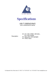
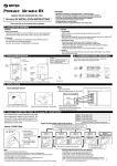
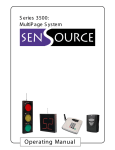
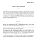
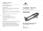
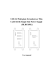
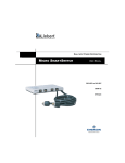
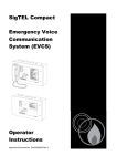
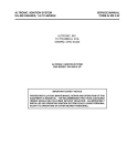
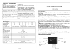
3890 Oakwood Ave.
Youngstown, OH 44515-3033
Phone: (800) 239-1226
Fax: (877) 517-2586
Commercial: www.SenSourceInc.com
Industrial: www.SenSource.biz
SS-RC10 Installation Guide & User’s Manual
GETTING STARTED: PLEASE READ THIS MANUAL CAREFULLY BEFORE INSTALLATION
Function:
•
•
Switch 1 – Activating “Learn Mode” and “Output Duration Mode”
Switch 2 – Activating “Volume Adjustment Mode” and making Selection
INSTALLATION METHODS
Mounting On A Wall – Using the mounting screw,
leave some length out of the wall for the mounting
hole of the SS-RC10.
Desk Top – Pull out the stand on the back of the
SS-RC10 and place it on any surface.
POWER CONNECTIONS
Use only the AC power adaptor supplied with the SS-RC10.
Page 1 of 4
TEACH TRANSMITTER CODES TO RECEIVER
Each transmitter has a unique transmission code which can be automatically “learned” by the SSRC10. The SS-RC10’s zones must be taught to respond to the appropriate transmitter. Zone
characteristics can be programmed as shown below.
Regular Mode
Zone 1: Chime tone 1 (optional timed utility output)
Zone 2: Chime tone 2 (optional timed utility output)
Zone 3: Chime tone 3 (optional timed utility output)
Zone 4: Continuous tone and terminal output (latches
until switch 2 is pressed to deactivate)
Activate “LEARN” Mode
Utility Output Mode
Zone 1: Chime tone 1 only
Zone 2: Chime tone 2 only
Zone 3: Timed relay output only (5 sec)
Zone 4: Continuous tone and terminal output (latches
until switch 2 is pressed to deactivate)
Note:
•
Return to normal operation status before use.
•
Verify that each transmitter has been learned by the
SS-RC10 by triggering them.
•
Each zone can accept a maximum of 3 transmitters, and
zone indicator shows the activated transmitter by the
number of flashes. eg. (If transmitter 2 in zone 1 is
activated, zone 1 indicator flashes twice)
•
Single transmitter cannot be learned by multiple zones.
•
Turning off the devices, or losing power, will not affect
transmitter or the SS-RC10’s code memory.
Erasing Codes from Receiver’s Memory
1. Hold down Switch 1 until the power indicator starts to flash.
2. Press Switch 2 until appropriate zone indicator is lit.
3. Press Switch 1 to erase. Zone indicator will start to flash.
(Note: All programming in that particular zone will be erased.)
4. Press Switch 2 a few times until the power indicator stops flashing and remains lit.
Note: To erase all programming and return to factory settings, turn on power while holding Switch 1.
LOW BATTERY INDICATION
Zone indicators start flashing whenever corresponding transmitters have a low battery. The receiver
will sound a chime followed by 2 beeps. Slow flashing of indicators will last until 1) batteries of
transmitters are replaced or 2) Switch 2 is pressed. In this case, replace transmitter batteries even if
they are less than 2 years old. You can not activate various adjustment modes in this state, unless
Switch 2 is pressed (indicators stop flashing). There is no need to go through adjustments again after
replacing batteries.
Checking the status indicator of transmitters at that particular zone is
recommended to identify the low battery transmitter.
Page 2 of 4
VOLUME ADJUSTMENT
Chime volume for zones 1–3 can only be set as a group. There are 5 volume settings.
After 5 seconds, the receiver will automatically return to normal
operation status (zone indicators will go off and power indicator
will remain lit).
Note: Hold down Switch 2 five seconds
for zone 4 (power indicator goes off and
zone indicator displays the current
setting).
TERMINAL CONNECTION
The terminal connection on the SS-RC10 could be used for external SenSource devices, such as the
PC-DISPLAY, PCDL-1000 and PCW-PC4. If provided, use the 2-lead BLK/WHT jacketed cable to
connect these devices. Connect the black lead to the COM terminal and the corresponding white lead
to the N.O. terminal.
ADJUSTING THE TERMINAL OUTPUT DURATION
•
•
•
•
In Regular Mode: Terminal output duration can be set for zones 1–3 only as a group.
Zone 4 always latches until it is reset by pressing Switch 2.
In Utility Output Mode: Terminal output (5 sec) is only for zone 3. Zone 1 and 2 will
chime only and zone 4 will latch until it is reset by pressing Switch 2.
Press Switch 1 twice within 2 seconds to activate terminal output duration mode (zone
indicators display the current settings).
After 5 seconds, the SS-RC10 will automatically return to normal operation status
(zone indicators will go off and power indicator will remain lit).
Page 3 of 4
DIMENSIONS:
UNITS – INCHES (mm)
SPECIFICATIONS
Model
Description
Power Source
Chime Tone
Volume
Status Indicator
Relay Output
Output Timer
Frequency
Operating Temperature
Installation Location
Accessories
Weight
SS-RC10
Wireless Receiver
DC 9V (Exclusive AC Adaptor): Standby – 1W / Operating – 2W
3 Tone & Continue Zone (Selectable)
Adjustable: 0 – 80dB/ 5 levels
Maximum Volume (Continue Zone)
Power Indicator: Green
Zone Indicator: Red X 3
Form “C” MAX 1A/50VAC · DC24VAC
Selectable: Off/1/5/30/60sec/ Utility Output Mode
418 MHz
15° F – 104° F (-10° C – +40° C)
Indoor
Mounting Screw X 1, AC Adaptor X 1
6.0 oz (170g)
TROUBLESHOOTING YOUR SS-RC10
Is the power indictor of the SS-RC10 lit?
Have all the transmitter codes been
taught correctly?
Is the volume setting correct?
Are there other high power appliances
using the same electrical power outlet?
Is there anything blocking the SS-RC10?
The zone indictor of the SS-RC10 is on,
but nothing happens.
Are zone indictors flashing slowly?
The SS-RC10 does not learn transmitter
codes.
The SS-RC10 gets reception in a wrong
zone.
The SS-RC10 does not respond to some
of the transmitters.
Æ
Æ
Æ
Æ
Is the receiver on? Check the wiring and connection.
Teach the transmitter codes correctly. The system will not
operate without this process.
Is the volume set to “0?” If so, readjust the volume.
Connect the SS-RC10 to another outlet.
Æ
Relocate the SS-RC10 to another location.
Check to see whether the terminal is properly connected to
Æ
other devices.
Æ Follow directions in “Low Battery Indication.”
Check if the transmitter code is not already “learned” in a
Æ
different zone. If it is, erase memory and teach again.
Erase memory in the zone the SS-RC10 responds and teach
Æ
in the correct zone.
You may have taught multiple transmitter codes in a same
Æ zone. Teach the transmitter code that has no response using
an empty zone.
Certain zone seems to malfunction.
Check the transmitter that corresponds to that zone. This is
Æ
probably caused by the transmitter.
Before contracting the supplier…
Go through the setups again after Turning on the power while
Æ
holding down the Switch 1.
• For further help, contact SenSource at 1-800-239-1226 or at info.SenSourceInc.com.
Page 4 of 4