1
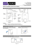
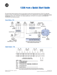
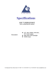
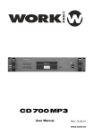
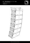
1257 Salt Springs Rd.
Youngstown, OH 44509-1612
Phone: (800) 239-1226
Fax: (877) 517-2586
Commercial: www.SenSourceInc.com
Industrial: www.SenSource.biz
PC-BX05 People Counter Installation Guide & User’s Manual
GETTING STARTED: PLEASE READ THIS MANUAL CAREFULLY BEFORE INSTALLATION
When installed as explained below, the photoelectric sensor emits an invisible beam of light that
travels across a maximum distance of 5 meters (~16ft) between sensor and the reflector. When a
person crosses this beam a digital signal is sent to the counter incrementing its display by +1. This unit
counts up regardless of the direction of traffic (entering or exiting). Removal of power to the display
does not reset the counter. It will maintain its count until the reset button on the display is depressed.
This system operates with a safe low voltage 12V DC supply (included).
Components:
• Counter Display
• Retroreflective Photoelectric Sensor
With 10ft Cable (W25xH65xL75mm)
• MS-4 Round Reflector (80mm diameter)
• 12V DC Power Supply With 10ft Cable
Optional Components:
• Count Recorder
• Chime
• Magnetic Reset
INSTALLATION
By following the simple guidelines below your people counter will be operating within a few minutes.
1. Adding Cable Length (Skip this step if you plan on using the standard 10ft cable provided)
1.1. You may use your own cable (according to the specifications listed in figure 2) if you wish to
extend the distance from the components (up to 1000ft with shielded cable). To remove the
sensor cover, loosen the screw on the sensor housing and pull the cover off exposing the wire
terminals. (Refer to Figures 1 and 2)
2. Mounting Components
2.1. Sensor: The sensor should be installed securely using the mounting brackets supplied with the
sensor at a level that people will break the beam (mounting screws not included). The sensor
is most effective when mounted about 3-4ft above the ground (aim at the torso section), or 4-5ft
to ignore children in counts. Plan to mount the reflector directly across from the sensor at a
distance no greater than 5 meters (16ft), but DO NOT PERMANENTLY MOUNT THE
REFLECTOR UNTIL STEP 4. Mounting suggestions are located in figure 4. (Refer to Figures
3 and 4)
2.2. Display and/or Chime: The display or chime can be set in any convenient indoor location or
mounted to a secure surface using the mounting flanges.
2.3. Count Recorder: If your system is equip with a PCDL-1000 Count Recorder, it is suggested to
mount the Count Recorder using Velcro (soft side applied to Count Recorder) in an area with
easy access but is limited to personnel only.
Page 1 of 4
3. Wiring Components
3.1. Power Supply/Transformer: Your system comes with a 2-conductor (red/blk) cable with fork
connectors on one end. Connect the fork terminals to the white power supply (CHECK
POLARITY) (Refer to Figure 2)
3.2. Display: Connect the wires from the sensor, power supply, Count Recorder1 and chime1 to the
back of the display according to the wiring diagram, while adhering to the wiring codes
established for your state and locality. Excess wire length can be trimmed. If a Count Recorder
is being used please follow the included instructions with the Count Recorder along with the
wiring guide in figure 2.
4. Aligning and Mounting Reflector
4.1. After the sensor, display and optional components have been mounted and wired, connect the
power supply to a 120V AC outlet and take note of the lights on the sensor. Focus your
attention on the yellow light.
4.2. The sensor and reflector should be aligned so that the yellow light is NOT illuminated when
nothing is blocking the path between the sensor and the reflector (the green light may or may
not be on). If the yellow light is illuminated, adjustments to the alignment of the reflector need
to be made until the yellow light remains off with nothing blocking the beam. Further
adjustments to the sensor alignment can be accomplished by loosening the screws on the
sensor bracket in order to point the sensor up or down or side to side.
4.3. Once aligned properly the yellow light will NOT be illuminated. When the beam is broken, the
yellow light will illuminate and the count will be incremented by +1. Make sure to secure the
reflector and sensor in order to maintain alignment.
4.4. The photoelectric sensor includes adjustments for both sensitivity and signal-delay2 located
under the sensor cover. These settings are factory set and should not require adjustment. If
adjustment becomes necessary due to unforeseen conditions, the time delay or sensitivity can
be increased or decreased by rotating the appropriate adjustment using the small blue
screwdriver provided. Turning clockwise will increase and counterclockwise will decrease.
Increasing the time delay is generally used to count groups of people as one count.
5. Your Counting System Is Ready For Operation
5.1. Resetting the Display: Pressing the black button to the right of the display will reset the counter
back to zero. If system is equipped with magnetic reset, apply supplied magnet to the area
labeled reset3. 1Optional component, 2Not available on all systems, 3Location may vary
WIRING DIAGRAMS
Yellow & Green LEDs
Reflector
Cable
Aim Sensor Face
At Reflector
Wire Holder
Sensor
Washer & Grommet
Mounting
Bracket
WARNING: DO NOT AIM YELLOW
LED AT THE REFLECTOR, SYSTEM
WILL NOT OPERATE.
Figure 1
Page 2 of 4
COUNTER DISPLAY (FRONT)
COUNTER DISPLAY (BACK)
_
+
12V DC
Power Supply
RESET AREA
RED
22AWG-2 Conductor
BLACK
+
RED
BLACK
_
IN
BX05 Sensor
STAB
OUT
(Green) (Yellow)
22AWG-3 Conductor
RED (3)
WHITE (1)
BLACK (5)
Dip Switches
RED
WHITE
BLACK
L-ON
1 4
25
3
D-ON
22AWG-2 Conductor
WHITE
MAX
SENS.
BLACK
COUNT RECORDER (OPTIONAL)
WHITE
+
_
BLACK
MIN
Yellow Light
PCDL-1000
CHIME (OPTIONAL)
IN
RED
WHITE
BLACK
22AWG-3 Conductor
_ +
RED
WHITE
BLACK
Figure 2
3.3
Sensing Area
Max Dist. = 5 Meters (16ft)
1.2
3.3
3.3
Display
Dimensions
Sensor
Reflector
12V DC
Supply
120 VAC
Outlet
Display
Figure 3
Page 3 of 4
SENSOR / REFLECTOR MOUNTING & ALIGNMENT
Top View of Entry
(Typical Installations)
Reflector
Reflector
20º max
Reflector
16ft Max
Option 1
Option 2
Option 3
Sensor
Sensor
Sensor
Front View of Entry
Sensor
Reflecto
Sensor should be mounted at
about 3 – 4ft above ground level
(aim at the torso or higher) or 4 –
5ft to ignore children in counts.
Figure 4
Page 4 of 4