1
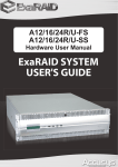
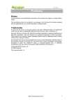
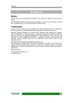
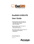
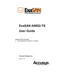
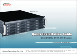
A12/16/24R/U-FS
A12/16/24R/U-SS
Quick Start Guide
ExaRAID SYSTEM
USER'S GUIDE
A12/16/24R/U-FS
A12/16/24R/U-SS
Quick Start Guide
42-33000-5028
ExaRAID SYSTEM
Version:1.1
Accusys A12R/U-FS&SS / A16R/U-FS&SS / A24R/U-FS&SS
Accusys RAID System Task List
Step 1. Unpacking the Accusys RAID System.
Step 2. Installing Disk Drives.
Step 3. System Connections and Management.
Step 4. Setting Up LAN Connections.
Step 5. Connecting the Power.
Step 6. Setting the RAID IP Address.
Step 7. Disk Array Configuration.
Step 8. Host Configuration.
Step 1. Unpacking the Accusys RAID System
The box contains the following items:
1
1. Hard disk tray: A12R/U-FS&SS x 12
A16R/U-FS&SS x 16
A24R/U-FS&SS x 24
2. External SAS (For SAS controllers only)
3. Front panel key x 2
8
9
10
11
12
13
2
4. RS-232 cable x 2
3
5. Power cable: A12/16R/U-FS&SS x 2
A24R/U-FS&SS x 3
4
6. CD x 1
5
Quick Start
Guide
6
7
14
Power
P/S Fail
Access
Enter
ESC
7. User manuals
8. M5 fix screw x 2 packs
9. M6 fix screw x 2 packs
10. UNC # 10-32 fix screw x 2 packs
11. Screw pack
12. Rail x 1 set
13. Rail extender x 1 set
14. RAID system
1
Accusys A12R/U-FS&SS / A16R/U-FS&SS / A24R/U-FS&SS
Step 2. Installing Disk Drives
Installing the Hard Disks
The RAID system supports SAS or SATA interface hard drives.
Caution
It is recommended to mount the RAID system to the rack cabinet
first before installing the hard drives and the drive trays. If the hard
drives are installed first, the RAID system may be too heavy to lift or
handle. And the possible impact during installation may damage the
drives.
Follow the procedures below to install hard drives:
1. Insert the SAS hard drive into the hard disk tray. Screw the sides to
secure the hard disk. Repeat this procedure to install more hard disks.
2. Insert the key to the key slot and turn to unlock the front panel door.
Enter
Power P/S Fail
ESC
Access
Enter
ESC
Fail Access
Power P/S
A16R/U-FS&SS
A12/24R/U-FS&SS
2
Accusys A12R/U-FS&SS / A16R/U-FS&SS / A24R/U-FS&SS
3. Pull open the front panel door.
4. Insert the hard disk trays into the empty slots.
5. Push down the tray handle to secure the hard disk tray into place.
6. Repeat steps 4 to 5 until all the required disks have been installed.
7. Close the front panel door, then lock it.
3
Accusys A12R/U-FS&SS / A16R/U-FS&SS / A24R/U-FS&SS
SATA hard disks
SATA hard drive installation requires an AA-MUX adapter to be installed
on the hard disk tray first before installing the SATA hard disk.
Note
AA-MUX is an optional accessory and is sold separately. Contact your
supplier to purchase one.
Follow the procedures below to install SATA hard disks:
1. Place the AA-MUX adapter on the hard disk tray and attach the four
screws as shown.
2. Place the hard disk into the hard disk tray with the drive connectors
facing the AA-MUX adapter.
4
Accusys A12R/U-FS&SS / A16R/U-FS&SS / A24R/U-FS&SS
3. Slide the hard disk towards the AA-MUX adapter and connect the
power and data connectors.
4. Attach the screws to secure the hard disk.
5
Accusys A12R/U-FS&SS / A16R/U-FS&SS / A24R/U-FS&SS
Mounting the RAID system
The RAID system/Rail Extenders can be installed in a standard 19-inch
rack. Follow the procedures below:
1. Attack eight rack nuts into the rack,
making sure that they correspond with
the mounting points on the rails.
2. Adjust the length of the rails as
needed.
3. Secure the rails using two nuts and
bolts on both the front and back posts
of the rack then tighten the locking
screws.
4. When necessary, install the rail
extenders by attaching the screws to
secure them.
5. Slide the RAID system into the rack
and secure it into place using the
fixing screws.
Power P/S Fail Access
Enter
ESC
6
Accusys A12R/U-FS&SS / A16R/U-FS&SS / A24R/U-FS&SS
Installing the Rail Extenders
Follow the procedures below to install the rail extenders:
1. Install the rail extenders and attach the
screws to secure them.
2. Slide the RAID system into the rack and
secure it into place using the fixing
screws.
Power P/S Fail Access
7
Enter
ESC
Accusys A12R/U-FS&SS / A16R/U-FS&SS / A24R/U-FS&SS
Step 3. System Connections and Management
Connecting to the Host
Connecting Fiber RAID System Controller to the Host
A12R/U-FS, A16R/U-FS, and A24R/U-FS have dual 4G fiber channel
interfaces on each controller. Each channel interface can be
connected using an optical or copper transceivers and cables.
To connect an optical cable, simply insert the cable to the CH1 port.
You can configure your RAID system for:
• Storage Area Network (SAN)
• Direct Attached Storage (DAS)
• JBOD Expansion using a SAS data connection
To connect an LC optical SFP transceiver, follow the procedures below:
1. Insert the SFP transceiver into the CH1 port.
2. Then connect the optical cable to the SFP transceiver.
1
2
3. Connect the other end of the optical cable to the HBA connector of
the host server.
Configuring a Storage Area Network
A storage area network (SAN) requires:
• A Fibre Channel switch
• A Fibre Channel HBA card in each Host PC/Server
• A network switch
• A network interface card (NIC) in each Host PC/Server
8
Accusys A12R/U-FS&SS / A16R/U-FS&SS / A24R/U-FS&SS
To establish the data path:
1. Connect one of the Fibre Channel data ports on the RAID system’s
controller to your Fibre Channel switch.
2. Connect each Host PC’s or Server’s standard NIC to your network
switch.
Host Group 1
HOST SERVER
Host Group 2
HOST SERVER
LAN Switch
FC Switch
Loop1
Loop2
Host 2
Host 3
Host 1
Host 4
Fibre Card A
1
Na
WP
WW
Nb1
WP
WW
FCPa2
Fibre Card B
W
W
W
PN
a2
FCPa1
FCPb2
WW
WP
Nb
2
FCPb1
Controller B
12
45 6
78
3
Controller A
90
Configuring Direct Attached Storage
Direct attached storage (DAS) requires:
• Two Fibre Channel HBA cards in the Host PC or Server
• A network switch
• A network interface card (NIC) in the Host PC or Server
To establish the data path:
Connect one of the Fibre Channel data ports on the RAID system
controller to your Fibre Channel switch.
9
Accusys A12R/U-FS&SS / A16R/U-FS&SS / A24R/U-FS&SS
To establish the management path:
1. Connect the Management port on the RAID system controller to your
network switch.
2. Connect the Host PC’s or Server’s standard NIC to your network switch.
LAN Switch
Fibre Card
Fibre Card
FCPa2
FCPa1
FCPb2
FCPb1
Controller B
8
12
45
67
3
Controller A
10
90
Accusys A12R/U-FS&SS / A16R/U-FS&SS / A24R/U-FS&SS
Connecting SAS RAID System Controller to the Host (SAS HBA
Card required)
1. Insert the SAS cable into the CH1 port.
2. Insert the other end to the HBA connector of the host server.
Note
The illustration above shows A16R-SS. Same procedures apply to
A12R/U-FS&SS, A16R/U-FS, and A24R/U-FS&SS.
Connecting the CLI Management Port
The RAID system can be managed using the CLI.
To connect the CLI port, follow the procedures below:
1. Insert the RS-232 cable into the COM port.
A16R-FS COM port connection
11
Accusys A12R/U-FS&SS / A16R/U-FS&SS / A24R/U-FS&SS
2. Insert the other end to the computer’s COM port.
Note
• Same procedures apply to A12R/U-FS&SS, A16R/U-SS, and A24R/
U-FS&SS.
• Please refer to the software user manual for more information on
CLI management.
Connecting JBOD (Sold separately)
Follow the procedures below to connect to A12R/U-SJ, A16R/U-SJ, or
A24R/U-SJ (JBOD).
1. Insert a SAS connector to the EXP port on the controller.
JBOD expansion on A16R-FS
2. Connect the other end to the CH1 port of the JBOD system.
3. Power/Fan/Temp/HDD LED on JBOD lights up green and IO1&2 LED
flashes when the connections are set up properly.
12
Accusys A12R/U-FS&SS / A16R/U-FS&SS / A24R/U-FS&SS
Step 4. Setting Up LAN Connections
LAN communication enables the Command Line Interface (CLI) and
Graphic User Interface (GUI) on your PC to monitor and control the RAID
system to easily monitor and configure the RAID system.
A LAN/WAN connection is required. Follow the procedures below:
To set up a LAN cable connection:
1. Attach one end of the ethernet cable to the LAN port on one of the
Controller board.
2. Attach the other end of the ethernet cable to a LAN switch or directly
to a LAN port on the Host PC or Server using a crossover cable.
13
Accusys A12R/U-FS&SS / A16R/U-FS&SS / A24R/U-FS&SS
Step 5. Connecting the Power
Once all of the components have been installed into the RAID system,
and the management interfaces have been connected, the RAID
system can now be powered on.
Power on:
1. Plug one power cable into the AC power port.
A12R/U
1
A
A16R/U
P/ S 2
Co nt ra
lle r A
P/ S 1
A24R/U
2. Plug the second power cable into the other AC power port.
3. Turn on the power switch.
14
Accusys A12R/U-FS&SS / A16R/U-FS&SS / A24R/U-FS&SS
Power off:
Before you power off the system, make sure all the running process are
completed on the host computer.
Please follow the following procedure to shut down your system properly.
By LCD
1. Log in from the LCD panel by inputting the password. The default
password is “0000”. See Set up through LCD on page 16 for instructions
on using the LCD panel.
2. Select System Setup > Shutdown > Yes to power off the system.
By GUI
1. Open a browser and enter the RAID system’s IP address in the address
field. (The default IP address is 192.168.0.1)
2. Log in from GUI to open the Config Mode. The default username and
password are “admin” and “0000”.
3. Click System Management > Restart/Halt to open the Restart/Halt
page.
4. Select Both Controllers from the Controller ID drop down menu and
select Halt from the Action drop down menu and click Apply.
5. Click Confirm to confirm and shut down the system.
6. Turn the power off when the LCD displays “Ready to power off!”.
15
Accusys A12R/U-FS&SS / A16R/U-FS&SS / A24R/U-FS&SS
Step 6. Setting the RAID IP Address
Choosing DHCP or a Static IP Address
When you setup your RAID system, you have the option of:
• Enabling DHCP and letting your DHCP server assign the IP address to
the
RAID system’s virtual management port.
• Specifying a static IP address for the RAID system’s virtual management
port.
If you choose to enable DHCP, have your Network Administrator
dedicate an IP address for the RAID system, linked to the RAID system’s
GUI.
Set up through LCD
The RAID system has a front LCD panel which supports a quick
configuration and RAID monitoring. You can use the four buttons on the
LCD panel to manipulate the LCD configuration utility.
• UP/DOWN: Use to select the numbers 0 to 9, characters “a” to “z”, or scroll
through menu items.
• Enter: Use to enter the selected character, confirm the password if no character
is selected, or select items in the menu.
• ESC: Backspace, or go back to the previous screen.
To set up the IP Address through LCD:
1. Power on the RAID system and wait for the boot up to complete.
2. Input the password using the four buttons to enter the menu. The
default password is “0000”.
3. Go to Ethernet Setup in the menu and select the Controller (CTL A or
CTL B) you want to configure.
4. Select Set DHCP and select Static IP or DHCP depending on your server
settings.
5. Input the necessary information such as IP address, net mask, gateway,
and DNS.
16
Accusys A12R/U-FS&SS / A16R/U-FS&SS / A24R/U-FS&SS
6. Go to System Setup > Save Config > Save to NVRAM > YES in the menu
to save your settings.
Note
When LAN or WAN is not available, use a HUB or crossover LAN
cables to connect to a computer to setup IP then manage the RAID
system by GUI. Set the IP as follows:
Controller A LAN = 192.168.1.1
Controller B LAN = 192.168.0.1
Set up through CLI
The Command Line Interface (CLI) is a set of commands which allows
users to configure or monitor the RAID system by entering lines of text
through a variety of the terminal consoles.
The embedded CLI can be accessed remotely by the Ethernet (TCP/IP)
and locally by the RS232 terminal. And by Ethernet, you may use Telnet
and SSH (Secure Shell).
Telnet client software is available for all operating systems, and you can
download the SSH client software from the following web sites:
SSHWinClient: http://www.ssh.com/
PuTTY: http://www.chiark.greenend.org.uk/~sgtatham/putty/
To set up the IP Address through CLI:
1. Establish LAN communications with the RAID controller. See Step 4.
Setting Up LAN Connections on page 13 for more details.
2. Open your terminal program and log in to CLI using the following
information:
•User name: admin
•Password: 0000
3. Use the following command to set up the IP address.
17
Command
ethsetaddr
Synopsis
ethsetaddr ethx method [-a] ip_addr [-s] net_mask [g] gw_addr [-d] dns_addr [-z] on/off
Description
Set IP address of an Ethernet port
Parameters
method: static or dhcp
[-a]: network address
[-s]: network mask
[-g]: gateway address
[-d]: DNS server address
[-z]: Automatic Private IP Addressing (APIPA)
Accusys A12R/U-FS&SS / A16R/U-FS&SS / A24R/U-FS&SS
For example:
Controller A
CLI> ethsetaddr etha1 static -a 192.168.0.1 -s 255.255.255.0 -g
192.168.0.1 -d 192.168.10.1
Controller B
CLI> ethsetaddr ethb1 static -a 192.168.0.2 -s 255.255.255.0 -g
192.168.0.1 -d 192.168.10.1
Note
Please refer to the software user manual for more information on the
set up.
18
Accusys A12R/U-FS&SS / A16R/U-FS&SS / A24R/U-FS&SS
Step 7. Disk Array Configuration
Quick Setup
Note
Quick setup can be compeleted using the LCD or GUI. Please refer to
the following settings for reference.
To perform quick setup, all hard disks must be on-line and unused. For an
easy configuration, users can specify the RAID level, number of spare
disks, and initialization option. Refer to the table below for details of each
option.
HDD
Information
Shows the number and the minimum size of hard
disks.
RAID Level
RAID 0 / RAID 3 / RAID 5 / RAID 6 / RAID 10 / RAID
30 / RAID 50 / RAID 60
Spare Disks
Select the required number of global spare disks.
Initialization
Option
Background: The controller starts a background
task to initialize the logical disk by synchronizing
the data stored on the member disks of the logical
disk. This option is only available for logical disks
with parity-based and mirroring-based RAID levels.
The logical disk can be accessed immediately
after it is created.
Noinit: No initialization process, and the logical disk
can be accessed immediately after it is created.
There is no fault-tolerance capability even for
parity-based RAID levels.
Two volumes (for raid30, raid50, or raid60) or two logical disks (for other
RAID levels) will be created with the capacity of all disks in the RAID
enclosure. One volume will be based on two disk groups, so there will be
four disk groups in total. The preferred controller of one volume or logical
disk is assigned to controller A and the other is assigned to controller B.
They will be mapped to LUN 0 and LUN 1 of all host ports on both
controllers. All other configurations will remain unchanged, and all RAID
parameters will use the default values.
19
Accusys A12R/U-FS&SS / A16R/U-FS&SS / A24R/U-FS&SS
To set up through GUI
1. Select Quick Setup > Raid Setup.
2. Select the related settings as follows:
• RAID Level = RAID5
• Spare Disks = 0
• Initialization Option: Background
3. Click Apply to start assigining the first 8 hard disks to DG0 and the last 8
hard disks to DG1.
4. Create the logical disk for both disk groups.
5. After creating the logical disk, LUN mapping will automatically be
done.
To setup through LCD
1. Enter the password. The default password is “0000”.
2. From the main menu, select Quick Setup.
3. Select the related settings as follows:
• RAID Level = 5
• Spare Disks = 0
• Init Method: Background
4. The LCD will display the message “Quick setup OK” to indicate setup
has been carried out.
20
Accusys A12R/U-FS&SS / A16R/U-FS&SS / A24R/U-FS&SS
Simple storage
Simple storage is used in direct attached storage (DAS) environments.
Any computer is allowed to access the LUNs presented by the controller
after gaining access to the host ports of the controller. LUNs are assigned
to each virtual disk in the RAID so the host can address and access the
data in those devices. Follow the steps below to configure simple storage
LAN Switch
Fibre Card
Fibre Card
FCPa2
FCPa1
FCPb2
8
3
12
45
67
90
21
FCPb1
Controller B
Controller A
Accusys A12R/U-FS&SS / A16R/U-FS&SS / A24R/U-FS&SS
Task List for Creating DAS
A. Create Disk Groups
B. Create Logical Disks
C. LUN Mapping
A. Create Disk Groups
By GUI
1. Open a browser and enter the IP address in the address field. (The
default IP address is 192.168.0.1)
The supported browsers are listed as below:
• IE 6.x (Windows)
• IE 7.x (Windows)
• FireFox 1.x (Windows, Linux, and Mac)
• Safari 1.x and 2.x (Mac)
2. The following web page appears when the connection is made. To
login, enter the username and password. The default username and
password are “admin” and “0000”. You can then access the Config
Mode.
22
Accusys A12R/U-FS&SS / A16R/U-FS&SS / A24R/U-FS&SS
3. To make sure the hard disks are unused, click RAID Management from
the Config Mode menu to check the status.
4. Click Disk Groups from the Config Mode menu. The following screen
appears.
5. Click Create to open Create Disk Group screen.
6. Select a DG ID from the drop-down menu.
7. Use the system default name as dgx. ‘x’ is the DG identifier. Or
Uncheck the ‘Use system default name’ box and enter the name in
the Name field. The maximum name length is 63 bytes.
23
Accusys A12R/U-FS&SS / A16R/U-FS&SS / A24R/U-FS&SS
8. Highlight the disks to be grouped in Members and Spares and click
to move them to the Member Disks.
9. Click Apply to create the disk group.
10. Repeat steps 4 to 9 to create other disk groups.
By CLI
Disk Groups can also be created from CLI.
1. At the CLI prompt type in: hddlist all to check the status of the hard disk
and make sure they are unused.
2. Use the following command to create Disk Groups.
Command
dgcreate
Synopsis
dgcreate dgi hddx hddy ... [-n name] [-i par/seq] [-z]
[-s hddz,hdda, ...] [-t capacity]
Description
Create a disk group with member disks
Parameters
[-n name]: the name of a disk group
[-i par/seq]: logical disk initialization mode (parallel or
sequential)
[-z]: write-zero immediately
[-s hddz,hdda, ...]: local spare disks
[-t capacity]: capacity to truncate
For example:
CLI>dgcreate dg0 hdd1 hdd2 hdd3 hdd4 hdd5 hdd6 hdd7 hdd8
CLI>dgcreate dg1 hdd9 hdd10 hdd11 hdd12 hdd13 hdd14 hdd15
hdd16
24
Accusys A12R/U-FS&SS / A16R/U-FS&SS / A24R/U-FS&SS
B. Create Logical Disks
By GUI
1. Click Logical Disks from the Config Mode menu. The following screen
appears.
2. Click Create to open Create Logical Disk screen.
3. Select a DG ID from the drop-down menu. This is the disk group to be
assigned for logical disk setting.
4. Select an LD ID from the drop-down menu.
5. Use the system default name as dgxldy. ‘x’ is the DG identifier and ‘y’ is
the LD identifier. OR Uncheck the ‘Use system default name’ box and
enter the name in the Name field.
6. Select a RAID level for the logical disk. Different logical disks in a disk
group can have different RAID levels. However, when NRAID is
selected, there must be no non-NRAID logical disks in the same disk
group.
25
Accusys A12R/U-FS&SS / A16R/U-FS&SS / A24R/U-FS&SS
7. Enter an appropriate capacity for the logical disk. This determines the
number of sectors a logical disk can provide for data storage.
8. Select the preferred controller to be in charge of managing and
accessing the logical disk.
9. Click Apply to start creating the logical disk.
10. Repeat step 2 to 9 to create more logical disks.
For example:
By CLI
1. At the CLI prompt type in: hddlist all to check the status of the hard
disk.
2. Use the following command to create logical disk.
Command
ldcreate
Synopsis
ldcreate dgxldy capacity raidlevel [-s stripesize]
[-i initopt][-f x] [-o offset] [-n name] [-c ctlx]
Description
Create a logical disk
Parameters
capacity: logical disk capacity
raidlevel: raid0, raid5, raid3, raid1, raid6, raid10, or
nraid
[-s stripesize]: stripe size
[-i initopt]: initialization method
[-f x]: free chunk
[-o sector]: alignment offset
[-n name]: the name of a logical disk
[-c ctlx] (for redundant controller only): the preferred
controller of a logical disk
For example:
CLI>ldcreate dg0ld0 1000gb raid5 -s 128kb -i bkg -c ctla
CLI>ldcreate dg0ld1 1000gb raid5 -s 128kb -i bkg -c ctlb
CLI>ldcreate dg1ld0 1000gb raid5 -s 128kb -i bkg -c ctla
CLI>ldcreate dg0ld1 1000gb raid5 -s 128kb -i bkg -c ctlb
26
Accusys A12R/U-FS&SS / A16R/U-FS&SS / A24R/U-FS&SS
C. LUN Mapping
By GUI
1. Click Storage Provisioning from the Config Mode menu. The following
screen appears.
2. Click Simple method. The following confirmation message is displayed.
Click Confirm to continue.
3. Click Add to open Add LUN to Storage Port screen.
4. Select a HTP ID from the drop-down menu.
27
Accusys A12R/U-FS&SS / A16R/U-FS&SS / A24R/U-FS&SS
5. Select a LUN ID from the drop-down menu.
6. Select a virtual disk from the drop-down menu for LUN mapping.
7. Click Apply to start LUN mapping.
8. Repeat steps2 to 6 until you assigned all the disks.
For example:
9. Click RAID Management to see if the Mapping is correct.
By CLI
10. Use the following command to add a LUN ID to a virtual disk.
Command
htpaddlun
Synopsis
htpaddlun fcpx/sasx jbdy/dgyldz/voly/vvoly [-l lunz] [s
512b/1kb/2kb/4kb] [-g cylinder head sector] [-w wt/
wb]
htpaddlun scpx jbdy/dgyldz/voly/vvoly [-i scsi_id]
[-l lunz] [-s 512b/1kb/2kb/4kb] [-g cylinder head sector] [-w wt/wb]
Description
Add a LUN in a FC port with a virtual disk
Parameters
[-i scsi_id]: SCSI ID
Refer to sgaddlun for other parameters.
For example:
CLI>htpaddlun fcpa1 dg1ld0
CLI>htpaddlun fcpa1 dg0ld0
CLI>htpaddlun fcpa2 dg1ld0
CLI>htpaddlun fcpa2 dg0ld0
CLI>htpaddlun fcpb1 dg1ld0
CLI>htpaddlun fcpb1 dg0ld0
CLI>htpaddlun fcpb2 dg1ld0
CLI>htpaddlun fcpb2 dg0ld0
11. Type htplistlun all to see if the Mapping is correct.
28
Accusys A12R/U-FS&SS / A16R/U-FS&SS / A24R/U-FS&SS
Symmetric storage
Symmetric storage is used in environments where hosts are equipped
with multi-path IO (MPIO) driver or software that can handle multiple
paths (LUNs) to a virtual disk.
(Host1) WWPNb1:0x11111111111111111
(Host2) WWPNa1:0x22222222222222222
Host Group 1
HOST SERVER
(Host3) WWPNb2:0x33333333333333333
(Host4) WWPNa2:0x44444444444444444
Host Group 2
HOST SERVER
LAN Switch
FC Switch
Loop1
Loop2
Host 2
Host 3
Host 1
Host 4
Fibre Card A
1
Na
WP
WW
Nb1
WP
WW
FCPa2
FCPa1
FCPb2
3
78
12
45 6
90
Task List for Creating Small SAN
29
WW
WP
Nb
2
FCPb1
Controller B
Controller A
A. Create Hosts
B. Create Disk Groups
C. Create Logical Disks
D. LUN Mapping
Fibre Card B
W
W
W
PN
a2
Accusys A12R/U-FS&SS / A16R/U-FS&SS / A24R/U-FS&SS
A. Create Hosts
By GUI
1. Open a browser and enter the IP address in the address field. (The
default IP address is 192.168.0.1)
The supported browsers are listed as below:
• IE 6.x (Windows)
• IE 7.x (Windows)
• FireFox 1.x (Windows, Linux, and Mac)
• Safari 1.x and 2.x (Mac)
2. To login, enter the username and password. The default username and
password are “admin” and “0000”. You can then access the Config
Mode.
3. To make sure the hard disks are unused, click RAID Management from
the Config Mode menu to check the status.
4. Click Storage Provisioning from the Config Mode menu to open
submenu.
5. Select Symmetric method. The following confirmation message is
displayed. Click Confirm to continue.
6. Click Host > Add to start creating hosts.
30
Accusys A12R/U-FS&SS / A16R/U-FS&SS / A24R/U-FS&SS
7. Click Host ID and select a Host ID from the drop-down menu. A
maximum of 32 hosts can be added to the controller.
8. Choose each WWPN of Fiber HBA from the ‘Choose from detected
hosts’ box or directly enter the WWPN in this field. Each FC port needs
a WWPN for communicating with other devices in an FC domain.
9. Enter the SAS address. SAS Address is needed for communicating with
other devices in an SAS domain.
10. Enter the Host name. Use the system default name as hostx. ‘x’ is the
Host identifier. OR Uncheck the ‘Use system default name’ box and
enter the name in the Name field. The maximum name length is 63
bytes.
11. Select a Host Group ID (HG ID) from the drop-down menu. You can
select from hg0 to hg31 or No group. This setting is required for
symmetric method.
For example:
12. Repeat steps 6 to 11 to create more hosts.
31
Accusys A12R/U-FS&SS / A16R/U-FS&SS / A24R/U-FS&SS
BY CLI
Hosts can also be created from CLI.
1. Log on to CLI using the following information:
• User name: admin
• Password: 0000
2. At the CLI prompt type in: hddlist all to check the status of the hard disk
and make sure they are unused.
3. Use the following command to create hosts.
Command
hostcreate
Synopsis
hostcreate hostx WWN [-n name]
Description
Create a host with WWN
Parameters
[-n name]: host name
For example:
CLI>hostcreate host1 1111111111111111
CLI>hostcreate host2 2222222222222222
CLI>hostcreate host3 3333333333333333
CLI>hostcreate host4 4444444444444444
4. Use the following command to create host groups.
Command
hgaddhost
Synopsis
hgaddhost hgx hostx hosty ...
Description
Add hosts to a host group
For example:
CLI>hgaddhost hg0 host1 host2
CLI>hgaddhost hg1 host3 host4
5. Type in hostlist all at CLI prompt to check the created hosts.
32
Accusys A12R/U-FS&SS / A16R/U-FS&SS / A24R/U-FS&SS
B. Create Disk Groups
By GUI
1. Click Disk Groups from the Config Mode menu. The following screen
appears.
2. Click Create to open Create Disk Group screen.
3. Select a DG ID from the drop-down menu.
4. Use the system default name as dgx. ‘x’ is the DG identifier. Or
Uncheck the ‘Use system default name’ box and enter the name in
the Name field. The maximum name length is 63 bytes.
5. Highlight the disks to be grouped in Members and Spares and click
to move them to the Member Disks.
6. Click Apply to create the disk group.
7. Repeat steps 2 to 6 to create other disk groups.
33
Accusys A12R/U-FS&SS / A16R/U-FS&SS / A24R/U-FS&SS
By CLI
Disk Groups can also be created from CLI.
1. At the CLI prompt type in: hddlist all to check the status of the hard disk
and make sure they are unused.
2. Use the following command to create Disk Groups.
Command
dgcreate
Synopsis
dgcreate dgi hddx hddy ... [-n name] [-i par/seq] [-z]
[-s hddz,hdda, ...] [-t capacity]
Description
Create a disk group with member disks
Parameters
[-n name]: the name of a disk group
[-i par/seq]: logical disk initialization mode (parallel or
sequential)
[-z]: write-zero immediately
[-s hddz,hdda, ...]: local spare disks
[-t capacity]: capacity to truncate
For example:
CLI>dgcreate dg0 hdd1 hdd2 hdd3 hdd4 hdd5 hdd6 hdd7 hdd8
CLI>dgcreate dg1 hdd9 hdd10 hdd11 hdd12 hdd13 hdd14 hdd15
hdd16
C. Create Logical Disks
By GUI
1. Click Logical Disks from the Config Mode menu. The following screen
appears.
34
Accusys A12R/U-FS&SS / A16R/U-FS&SS / A24R/U-FS&SS
2. Click Create to open Create Logical Disk screen.
3. Select a DG ID from the drop-down menu. This is the disk group to be
assigned for logical disk setting.
4. Select an LD ID from the drop-down menu.
5. Use the system default name as dgxldy. ‘x’ is the DG identifier and ‘y’ is
the LD identifier. OR Uncheck the ‘Use system default name’ box and
enter the name in the Name field.
6. Select a RAID level for the logical disk. Different logical disks in a disk
group can have different RAID levels. However, when NRAID is
selected, there must be no non-NRAID logical disks in the same disk
group.
7. Enter an appropriate capacity for the logical disk. This determines the
number of sectors a logical disk can provide for data storage.
8. Select the preferred controller to be in charge of managing and
accessing the logical disk.
9. Click Apply to start creating the logical disk.
10. Repeat steps 2 to 9 to create more logical disks.
35
Accusys A12R/U-FS&SS / A16R/U-FS&SS / A24R/U-FS&SS
For example:
By CLI
1. At the CLI prompt type in: hddlist all to check the status of the hard
disk.
2. Use the following command to create logical disk.
Command
ldcreate
Synopsis
ldcreate dgxldy capacity raidlevel [-s stripesize]
[-i initopt][-f x] [-o offset] [-n name] [-c ctlx]
Description
Create a logical disk
Parameters
capacity: logical disk capacity
raidlevel: raid0, raid5, raid3, raid1, raid6, raid10, or
nraid
[-s stripesize]: stripe size
[-i initopt]: initialization method
[-f x]: free chunk
[-o sector]: alignment offset
[-n name]: the name of a logical disk
[-c ctlx] (for redundant controller only): the preferred
controller of a logical disk
For example:
CLI>ldcreate dg0ld0 1000gb raid5 -s 128kb -i bkg -c ctla
CLI>ldcreate dg0ld1 1000gb raid5 -s 128kb -i bkg -c ctlb
CLI>ldcreate dg1ld0 1000gb raid5 -s 128kb -i bkg -c ctla
CLI>ldcreate dg0ld1 1000gb raid5 -s 128kb -i bkg -c ctlb
36
Accusys A12R/U-FS&SS / A16R/U-FS&SS / A24R/U-FS&SS
D. LUN Mapping
By GUI
1. Click Storage Provisioning from the Config Mode menu. The following
screen appears.
2. Click Add to open Add LUN to Host screen.
3. Select a Host Group ID from the drop-down menu.
4. Select a LUN ID from the drop-down menu.
5. Select a virtual disk from the drop-down menu for LUN mapping.
6. Click Apply to start LUN mapping.
7. Repeat steps2 to 6 until you assigned all the disks.
37
Accusys A12R/U-FS&SS / A16R/U-FS&SS / A24R/U-FS&SS
8. Click RAID Management to see if the Mapping is correct.
By CLI
1. Use the following command to add a LUN ID to a virtual disk.
Command
hgaddlun
Synopsis
hgaddlun hgx jbdy/dgyldz/voly/vvoly [-l lunz] [-s
512b/1kb/2kb/4kb] [-g cylinder head sector] [-w wt/
wb]
Description
Add a LUN in a host group with a virtual disk
Parameters
Refer to sgaddlun for all parameters
For example:
CLI>hgaddlun hg0 dg0ld0
CLI>hgaddlun hg0 dg0ld1
CLI>hgaddlun hg1 dg1ld0
CLI>hgaddlun hg1 dg0ld1
2. Type htplistlun all to see if the Mapping is correct.
38
Accusys A12R/U-FS&SS / A16R/U-FS&SS / A24R/U-FS&SS
Step 8. Host Configuration
Windows Multi−Path Solution: PathGuard
PathGuard is the bundled multi-path IO solution for Windows platforms,
and it is based on Microsoft Multipath I/O (MPIO) framework. PathGuard
consists of MPIO drivers and a web-based path manager GUI that allows
you to manage MPIO configurations for multiple host computers.
The MPIO drivers include standard drivers from Microsoft and DSM
(Device Specific Module) provided by the RAID system supplier.
The following steps are required for enabling PathGuard MPIO:
1. Complete the hardware and software setup at RAID systems.
2. Install the PathGuard package to the host computer. Register the
vendor name and model name of your RAID system to the PathGuard
(optional).
3. Install the PathGuard MPIO driver.
4. Reboot the host computer.
5. Launch PathGuard GUI to set multi-path policies.
Windows MPIO framework requires rebooting the host computer when
enabling the MPIO driver on the host computer, such that the regular
disk device drivers will be replaced by the MPIO disk drivers.
Windows can properly detect multi-path disks only during MPIO driver
installation, so reconfiguration (like adding/removing paths or LUNs)
requires you to reinstall the PathGuard MPIO driver and reboot the host
computer.
You might need also to manually rescan the physical drives (use
Computer Management > Storage > Disk Management) When multi-path
disks are not properly detected.
39
Accusys A12R/U-FS&SS / A16R/U-FS&SS / A24R/U-FS&SS
To Install PathGuard and MPIO Driver:
1. To install the PathGuard and MPIO Driver, double click the installation
file on a host computer (choose the 32-bit or 64-bit installation file
according to your host system).
2. Follow the on-screen instructions to start the installation. PathGuard
and the MPIO Driver will be installed automatically.
3. Reboot the host computer, and you have completed the installation.
Check the MPIO disk status on the host computer
After the PathGuard and the MPIO Driver has been installed, you can
find the new multi-path disk device(s) and the Multi-Path Support
displayed in the following screen: Computer Management > Device
Manager. (Right-click the My Computer icon on the desktop > select
Manage)
40
Accusys A12R/U-FS&SS / A16R/U-FS&SS / A24R/U-FS&SS
1. Go to Computer Management > Device Manager > Disk Drivers and
SCSI and RAID controllers to check for the Multi-Path Disk Device and
Multi-Path Support. The following illustration shows a successful
installation with Multi-Path Disk Device and Multi-Path Support found in
the Device Manager.
2. Make sure the two installed disk devices are in the Disk Management
as shown in the illustration. After that, you may format the new disk
devices and start using them.
41
Accusys A12R/U-FS&SS / A16R/U-FS&SS / A24R/U-FS&SS
Trouble Shooting
General Guidelines
When you encounter issues, the most essential troubleshooting is to
check the event log of your RAID system. In addition, you may need to
check the system log of the operating system at your host computers.
Because there are a wide variety of hardware and software
combinations, use the following checklist for problem determination:
• Check all cables to make sure they are connected properly.
• Check all hardware units are powered on and working properly.
• Check any recent changes in hardware, software, or configurations.
• Verify that the latest version of firmware and software are used.
• Verify that the latest version of BIOS and device driver of HBA are used.
• Verify that the operating systems, HBAs, switches, transceivers, and
hard disks are in the compatibility list.
• Check how to reproduce the problems.
Before you call support, please collect the related information above to
assist the support staff in identifying the problems. It is also required to
acquire the following three log files:
(1) RAID system user-level event log in human-readable form (.csv or .txt).
(2) RAID system diagnostic-level event log (.bin).
(3) the log file at operating system.
42
Accusys A12R/U-FS&SS / A16R/U-FS&SS / A24R/U-FS&SS
Beeper
When the Beeper Control is set to On, the system will turn on the beeper
alarm if one of the following occurs. If the user mutes the beeper via CLI,
LCD, or GUI, the system temporarily mutes the beeper until a new failure
or error occurs.
• Voltage failure or error.
• Power supply failure or error.
• Fan failure or error.
• Temperature failure or error.
• BBM failure or error (when BBM is connected).
• Disk SMART warning.
• Disk bad block over threshold warning.
• Disk group with degraded logical disk and no disk for rebuilding.
• Disk group with faulty logical disks.
• UPS failure or error.
• Controller failure or removed.
• Dual controllers fail to boot up because of configuration conflict.
• Controller failback cannot proceed.
43
Accusys A12R/U-FS&SS / A16R/U-FS&SS / A24R/U-FS&SS
Solutions
See the table below for the solutions for the most common problems.
Problem
Cause
Solution
Hard disks cannot be If a hard disk cannot be
recognized by the
ready within a specific period
RAID controller.
of time during the
initialization, the RAID controller will force the hard disks
enter faulty state and you
cannot see any model
information of hard disks.
To ensure hard disks have enough
time for power-on, you may extend
the delay time when boot-up of the
RAID controller.
Hard disks are offline Internal component failure or
unexpected.
reserved space for metadata (RAID configurations)
can not be written.
1. Use SMART check or DST
(Device Self-Test) to test the hard
disks in question.
2. Check the number of bad blocks
and warning events reported by
the RAID controller.
Exceptional hard
disks behaviors.
Adjust hard disk settings such as:
• Extend Disk I/O Timeout to
accommodate slow disk operation.
• Increase Disk I/O Retry Time to try
I/O more times before giving up.
• Reduce Transfer Speed to mitigate bad signal quality of disks.
• Disable I/O Queue to avoid
problematic NCQ support of disks.
• Disable Disk Standby Mode to
avoid problematic sleep support of
disks.
• Extend Disk Access Delay Time to
allow longer time for disk spin-up.
Hardware is not setup
properly.
Multiple hard disks
Could be system-level
Use array recovery utility to the RAID
are taken offline at a problem. For example, if the configurations. See the User’s mantime.
hard disks in a JBOD system
ual for more details.
are offline unexpected, poor
cabling in SAS or SAS expansion chain would also lead to
unexpected hard disk offline.
In addition, poor heat ventilation, unstable power supply,
or hardware quality issues
could also lead to offline of
multiple hard disks.
44
Accusys A12R/U-FS&SS / A16R/U-FS&SS / A24R/U-FS&SS
45
The Web GUI can not The management network
be connected.
interface is not configured
properly.
Check if the LED indicators of the
Ethernet port are lit up properly
(refer to the hardware manual for
details), and the IP address has to
be set to enable the network
interface. You can manually set the
IP address by the LCD or local CLI,
or use a DHCP server on the
network.
The replacement
controller stops bootup with LCD
messages.
(A/B/C) Contact your RAID system
supplier to get the correct controller.
(D/E) Install proper memory
module and BBM.
For (F) and (G), press the ENT
button on the LCD to update the
boot code and firmware code,
respectively, and the replacement
controller will reboot.
For (H) and (I), press the ENT button
to overwrite the BBM and enclosure
serial number, and the replacement controller will continue bootup.
Configuration conflict
discovered by the system.
The beeper alerts, and the
LCD shows the following messages:
(A) CONTR MOD UNEQ: the
two controllers are of different model.
(B) DB UNEQ: the two controllers have different daughter
board.
(C) PLD VERS UNEQ: the two
controllers have different PLD
version.
(D) MEM SZ UNEQ: the two
controllers install memory of
different size.
(E) BBM INSTL UNEQ: one controller has BBM, while the
other has no BBM.
If the conflict configuration
can be resolved by overwriting the configuration of the
replacement controller, the
following LCD messages will
be displayed and waiting for
your confirmation by LCD ENT
button:
( F) CHK BC VERS: the two
controllers have different
boot code version.
(G) CHK FW VERS: the two
controllers have different firmware code version.
(H) CHK BBM OPT: the two
controllers have different BBM
option.
( I ) CHK SN UNEQ: the two
controllers belong to
different enclosures.
Accusys A12R/U-FS&SS / A16R/U-FS&SS / A24R/U-FS&SS
Hard disk shows
Unknown state.
The configurations on the
hard disks cannot be recognized by the controller.
Erase the configuration information
on the hard disks for your RAID
system to use the hard disks.
Disk group enters
degraded mode.
Member disks are not
available.
Use the Array Recovery
Utility to restore the disks to the
degraded disk group. See User’s
manual for more details.
Hard disk shows
Conflict state.
1. Cache unit size of the
controller is bigger than the
stripe size of the logical disk
on the hard disks.
2. A disk group with the same
disk group ID of the hard
disks.
3. incompatible firmware
version.
1. change the cache unit size.
2. use Array Roaming Utilities
to import the hard disks to form a
disk group with a new disk group ID.
See the User’s manual for more
details.
3. erase the configuration information on the hard disks for your RAID
system to use the hard disks. Or,
contact your system supplier for
solutions.
46
Accusys A12R/U-FS&SS / A16R/U-FS&SS / A24R/U-FS&SS
Company Contact
Accusys, Inc.
•
5F., No.38, Taiyuan St., Jhubei City, Hsinchu County 30265, Taiwan(R.O.C)
•
Tel: +886-3-560-0288
•
Fax: +886-3-560-0299
•
http://www.accusys.com.tw/
•
E-mail: [email protected]
Accusys U.S.A., Inc.
•
1321 W. Foothill Blvd. Azusa, CA91702
•
Tel: +1-510-661-0800
•
Fax: +1-510-661-9800
•
http://www.accusys.com.tw
•
E-mail: [email protected]
Accusys Korea, Inc.
•
Baegang B/D 5F Shinsa-Dong 666-14 Kangnam-Gu, Seoul, Korea
•
Tel: +82 (02) 6245-9050
•
Fax: +82 (02) 3443-9050
•
http://www.accusys.co.kr/
•
E-mail: [email protected]
Accusys China(Beijing), Inc.
•
No. 9A, Tower B, Yingdu Mansion, No. 48 Zhichunlu Street, Haidian District, Beijing, China
(100098)
•
Ftp://ftp.accusys.com.cn
•
E-mail: [email protected]
•
Tel: +86-10-58734580/81/82/83
•
Fax: +86-10-58734585
•
E-mail: [email protected]
•
http://www.accusys.com.tw
Accusys China(Shanghai), Inc.
47
•
Room 701, No. 666, Kirin Tower, Gubei Road, Changning Area Shanghai, ZIP: 200336,
China
•
Tel: +86-21-6270-8599
•
Fax: +86-21-6270-8580
•
E-mail: [email protected]
Accusys A12R/U-FS&SS / A16R/U-FS&SS / A24R/U-FS&SS
Accusys EU B.V
•
Orionweg 6, 4782 SC Moerdijk, The Netherlands
•
Tel: +31 (0) 102995758
•
Fax: +31 (0) 168358621
•
http://www.accusys.com.tw
•
E-mail: [email protected], [email protected]
48