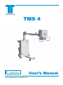
1
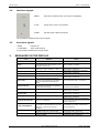
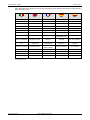
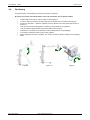
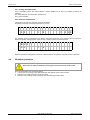
TECHNIX
TMS 4
Revision:
Version:
File:
B
October 26, 2009
[202363-00-01-B.doc]
User’s Manual
WARNING: The information that is printed within this manual is vital for a correct use of the equipment;
please carefully read it any time before use.
User's Manual - TMS 4
Technix S.p.A.
(This page is intentionally left blank)
[File: 202363-00-01-B.doc]
Technix S.p.A.
TMS 4 - User's Manual
SUMMARY
1.
SAFETIES AND CONFORMITIES................................................................................................. 2
1.1.
Electrical safeties .................................................................................................................. 2
1.2.
Mechanical safeties............................................................................................................... 2
1.3.
Electromagnetic compatibility (EMC)..................................................................................... 3
1.4.
Protection against ionizing radiation...................................................................................... 3
1.5.
General disposal ................................................................................................................... 4
1.6.
Interfaceability ....................................................................................................................... 4
1.7.
Copyright............................................................................................................................... 4
1.8.
Applications & use destination .............................................................................................. 5
1.9.
Classification ......................................................................................................................... 6
1.10. Regulations list for the evaluation of the product conformity ................................................. 6
1.11. Conformity............................................................................................................................. 6
2.
LEGEND ........................................................................................................................................ 7
2.1.
Overview ............................................................................................................................... 7
2.2.
Collimator .............................................................................................................................. 7
2.3.
Control panel......................................................................................................................... 8
2.4.
Luminous signals .................................................................................................................. 9
2.5.
Acoustical signals.................................................................................................................. 9
3.
MESSAGES ON THE DISPLAY .................................................................................................... 9
4.
FUNCTIONING ............................................................................................................................ 11
4.1.
Transport............................................................................................................................. 11
4.2.
Positioning........................................................................................................................... 12
4.3.
Setting in and verifications upon ignition ............................................................................. 13
4.4.
Collimator adjustment.......................................................................................................... 13
4.5.
Exposures ........................................................................................................................... 14
4.5.1. During the examination................................................................................................... 15
4.5.2. After the examination...................................................................................................... 15
4.6.
Shutdown procedure ........................................................................................................... 15
5.
MAINTENANCE........................................................................................................................... 16
5.1.
General Warnings ............................................................................................................... 16
5.2.
Checks and inspections by the user.................................................................................... 16
5.3.
Cleaning .............................................................................................................................. 17
5.4.
Disinfection.......................................................................................................................... 17
6.
TECHNICAL CHARACTERISTICS ............................................................................................. 18
6.1.
Electrical data...................................................................................................................... 18
6.2.
Functioning features............................................................................................................ 18
6.3.
Radiological data................................................................................................................. 19
6.4.
Environmental data ............................................................................................................. 20
6.5.
Mechanical data .................................................................................................................. 20
6.5.1. Unit sizes ........................................................................................................................ 21
6.6.
Components specifications ................................................................................................. 22
6.6.1. Generator ....................................................................................................................... 22
6.6.2. Tube-Housing Assembly................................................................................................. 23
6.6.3. Collimator ....................................................................................................................... 25
6.7.
Accessories and options ..................................................................................................... 25
6.8.
Labels and symbols............................................................................................................. 25
6.8.1. Labels of the unit ............................................................................................................ 25
DOCUMENT STATUS ............................................................................................................................. I
[File: 202363-00-01-B.doc]
Rev.0 - Pag. 1/26
User's Manual - TMS 4
1.
Technix S.p.A.
SAFETIES AND CONFORMITIES
Purpose of the present User’s Manual is to make the unit use friendly and safe. All the information herein
contained represent the current know-how status. Technix S.p.A. reserves the right to improve and upgrade
such information in function of the technological progresses.
•
•
This X-ray unit has to be used exclusively according to the safety instructions herein
contained and cannot be used for purposes other than those foreseen.
The X-ray unit has to be exclusively operated by qualified personnel, aware of the radiation
protections and precautions, properly trained about the use of X-ray units.
The operator is responsible for the use of the system in compliance with the applicable standards
concerning installation and use.
•
•
•
•
•
The unit must not be used when electrical, mechanical or radiological faults are present.
Besides, the system must not be utilized in case of malfunctioning of any signaling or alarm
device.
In case of use jointly with other apparatus, components or modules whose compatibility is
not certain, it is necessary to ensure the absence of any danger for patients or operators.
For this purpose, contact Technix S.p.A.
Technix S.p.A. is responsible for the safety of its own products only if their maintenance,
repair or modification have been performed by Technix S.p.A. or by personnel expressively
authorized by Technix S.p.A. itself by written notice.
As with any technical apparatus, this x-ray unit must be used properly with periodic checks
and maintenance as specified in the chapter “Planned maintenance”.
Circuits and safety devices must not, for any reason, be removed, modified or omitted.
Technix S.p.A. won’t be held liable for any malfunctioning, damages due to an improper use of the
system or non compliant with the maintenance rules.
1.1.
Electrical safeties
•
•
•
1.2.
Only trained service personnel authorized by Technix S.p.A. may remove the unit covers
and only in accordance with the instructions contained in the Service Manual.
This X-ray unit can be only used in environments or medical rooms complying with the
applicable IEC standards. The X-ray unit must not be utilized in areas where danger of
explosion exists.
The cleaning and disinfecting products, including the ones used for patients, may create
explosive and gaseous mixtures. Therefore, use only products in compliance with the
applying rules.
Mechanical safeties
•
•
•
Pag. 2/26- Rev.0
After positioning the unit, fix the stationary brakes.
To move the unit, only operate with the predisposed handles.
Avoid collisions with obstacles or similar.
[File: 202363-00-01-B.doc]
Technix S.p.A.
1.3.
TMS 4 - User's Manual
Electromagnetic compatibility (EMC)
According to the use foreseen, this apparatus complies with the IEC 60601-1-2, which defines the max.
allowed emission levels to the electronic devices and the required immunity against the electro-magnetic
fields.
It is not, however, possible to exclude radio signals coming from transmitters such as mobile phones or similar
mobile radio devices. These and other transmitting devices, including those in compliance with the EMC
standards, may influence the proper functioning of medical apparatus when used in proximity and with a
relatively high transmitting power. Therefore, in order to avoid any risk of interference, the use of these radio
equipments has to be avoided in proximity of electronically controlled systems.
Explanation:
The electronic apparatus that meets the EMC standards has been designed so that, under normal conditions,
any malfunctioning risk, caused by electromagnetic interferences, is avoided.
However, should radio signals be present, coming from high frequency transmitters with a relatively high
transmitting power, used near the electronic apparatus, the risk of electromagnetic incompatibility, cannot be
completely controlled.
Any transmission with mobile radio equipment should be avoided.
Mobile phones should be switched off in areas close to the unit.
These rules must be applied when the unit is switched on (that means when the unit is
connected to the mains).
1.4.
Protection against ionizing radiation
Before performing any exposure, ensure that all the necessary protections and
precautions have been taken.
During the use of x-rays, personnel present in the room must comply with the following rules concerning
protection against ionizing radiation. Therefore pay attention to the following:
•
•
•
•
•
When necessary, use protective tools against radiation and in addition at the devices already foreseen on
the unit.
Use the dedicated radio protective aprons. A radio protective material equivalent to 0,35mm lead lowers of
99,95% a radiation of 50kV and of 94,5% one of 100kV.
The best protection against radiation is the distance; keep the max. distance both from X-ray source and
from exposure target. This is aimed to use all the length of the foot-switch controlling X-ray.
Avoid walking or standing in the direct X-ray beam.
Always use the smallest exposure field possible, properly closing the collimator diaphragms. The leaked
radiation depends on the volume of the irradiated object.
In any case never modify or disconnect the safety circuits foreseen for accidental
exposures.
[File: 202363-00-01-B.doc]
Rev.0 - Pag. 3/26
User's Manual - TMS 4
1.5.
Technix S.p.A.
General disposal
Technix S.p.A. produces X-ray systems advanced in terms of safety and environments protection. If the unit is
properly utilized, then no risk exists for persons and environment.
Due to the above reasons, the unit cannot be disposed of along with industrial or
domestic waste and it has to be regarded as special waste.
This symbol indicates that the wastes resulting from the electric and electronic units have not to
be disposed as undifferentiated town wastes and they have to be picked up separately.
The proper differentiated collection for the following start of the unit disused to the recycle,
treatment and disposal, compatible with the environment, aid to prevent possible negative
effects on the environment and health and it favours the recycle of materials that compose the
unit.
The abusive disposal of the product from the user implies the application of administrative
sanctions according to the Standards in force of the unit installation country.
For information concerning the dismantling modes of the units out of use, stick to the local
provisions or contact an representative authorized by the manufacturer.
For additional information, contact Technix S.p.A.
1.6.
Interfaceability
The device does not foresee the interaction with medicines; with the possibility to interface a dosimeter, as
optional. It complies with the safety requirements foreseen by the 93/42/EEC Directive. Liable is the operator
and/or anyone performing any interface that has not been evaluated and authorized by Technix S.p.A. by prior
written notice.
1.7.
Copyright
The original release of this manual is in Italian language (file: 202363-00-00), for any further information
please refer to the Italian version.
The software contained in the unit belongs to TTechnix S.p.A. When receiving the unit, the user acquires the
right to use the software in connection to the unit: this right is not exclusive and not transferable.
For any modification of the unit operations other than those foreseen, the prior written notice authorization by
Technix S.p.A. is required.
Pag. 4/26- Rev.0
[File: 202363-00-01-B.doc]
Technix S.p.A.
1.8.
TMS 4 - User's Manual
Applications & use destination
This is a mobile x-ray unit and it has been designed to satisfy a wide range of clinical applications; it must be
operated exclusively by qualified, trained personnel who has been informed of the risks linked to the use of
ionizing radiation.
Compactness and manoeuvrability make the unit movement fluent and accurate through doors, small rooms,
narrow aisles and lifts permitting to move among obstacles with accuracy, in narrow curves and among the
patients’ beds. The ergonomic design of the unit allows the operator an excellent visibility during the motion
and operations.
The monobloc arm, perfectly balanced, allows a free motion and positioning also in the more uncomfortable
positions. The shape of the basement allows its positioning and handling under the patients’ beds. The
position and the shape of the four antistatic wheels make it ideal for an easy motion also on coarse surfaces.
For this system, no continuous use is required.
The accidental contact of some unit parts with the patient is possible and the contact with the
operator is foreseen.
The contact with the patient is not invasive.
The contact with the operator is foreseen for reasons that are strictly linked to the use conditions.
(Use operations).
•
•
•
•
•
•
The unit is suitable for X-ray exams and diagnostic investigations, such as:
Operating theatre
Sport medicine
Plaster room
First aid
Pediatrics
Orthopedics
This X-ray unit must not be used in areas where danger of explosion exists.
[File: 202363-00-01-B.doc]
Rev.0 - Pag. 5/26
User's Manual - TMS 4
1.9.
Technix S.p.A.
Classification
Protection against electrical hazards
Protection against direct and indirect contact
Protection against water penetration
Use condition protection
1.10.
Class I
Unit, Type B with Type B applied part
Common protection (IPXO)
Continuous use with intermittent load
Regulations list for the evaluation of the product conformity
Reference
MDD 93/42/EEC class IIB according to Annex IX rule
10.
IEC 60601-1 2nd edition
IEC 60601-1-2 2nd edition
IEC 60601-1-3 1st edition
IEC 60601-1-4 1st edition
IEC 60601-2-7 2nd edition
IEC 60601-2-28 1st edition
IEC 60601-2-32 1st edition
ISO 14971:2000 1st edition
1.11.
Description
Medical Device Directive (CE mark)
Medical devices safety
Electromagnetic compatibility
Protection against ionizing radiation
Programmable electromedical systems
High voltage generators
Tube – housing groups
Mechanical safety aspects
Risk analysis
Conformity
This x-ray unit is in compliance with the electromedical devices
Directive 93/42 EEC class IIb and with the Annex IX rule 10.
For any further information
compliance please contact:
TECHNIX S.p.A.
Via E. Fermi, 45
24050 Grassobbio, BG (ITALY)
Tel: +39 (0)35-3846611
Fax: +39 (0)35-335675
Web: http://www.technix.it
E-mail: [email protected]
Pag. 6/26- Rev.B
concerning
the The manufacturer (according to the European
Directive 93/42/EEC) of the unit TMS 4 is:
TECHNIX S.p.A.
Via E. Fermi, 45
24050 Grassobbio, BG (ITALY)
Tel: +39 (0)35-3846611
Fax: +39 (0)35-335675
Web: http://www.technix.it
E-mail: [email protected]
[File: 202363-00-01-B.doc]
Technix S.p.A.
TMS 4 - User's Manual
2.
LEGEND
2.1.
Overview
1.
2.
3.
4.
5.
6.
7.
8.
9.
Monobloc
Goniometer
Collimator
Monobloc handle
x-ray handswitch
Cable reel
Equipotential node
Power supply cable
Brake pedal
10.
11.
12.
13.
14.
15.
16.
17.
Tilting pedal
Cassette holder
Magneto-thermic switch
Handle for unit movement
Control console
Arm safety lock for transport
Monobloc support arm
Safety lock for monobloc rotation
16
15
17
13
1
5
14
6
12
7
2
11
10
3
8
9
4
Figura 1
2.2.
Collimator
1.
2.
3.
Lamp switching ON for the luminous irradiation
on field indication
Longitudinal collimation
Trasversal collimation
4.
5.
Guides for the accessories or filters positioning
Retractile tape measure (placed on the
collimator rear part)
1
2
5
3
4
Figura 2
[File: 202363-00-01-B.doc]
Rev.0 - Pag. 7/26
User's Manual - TMS 4
2.3.
Technix S.p.A.
Control panel
All the keys are membrane type.
Figura 3
ON
Unit ON, the yellow led indicates that the unit is connected and
supplied
OFF
Unit OFF
COLLIMATOR
Collimator lamp ON
(the lighting is timed for about 30s)
kV+ kV-
mAs+ mAs-
Pag. 8/26- Rev.0
The key works only if the collimator is preset, instead the lamp lighting
occurs only through the key on the collimator front.
Possibility to modify kV values
Possibility to modify mAs values
RESET
Reset the alarm.
It cancels the configuration datum.
ENTER
Confirm the configuration datum.
[File: 202363-00-01-B.doc]
Technix S.p.A.
2.4.
TMS 4 - User's Manual
Luminous signals
READY
Green led, lit all the time the unit is ready for radiography.
X-RAY
Orange led, it means x-ray emission.
ALARM
Red led, signal of alarm intervention.
It is not possible to deactivate the luminous signals.
2.5.
Acoustical signals
3 BEEP
Exposure ok
1 LONG BEEP
Alarm, malfunctioning
It’s not possible to disable the acoustical signals.
3.
MESSAGES ON THE DISPLAY
Text
READY
Meaning
*** FAULT
The unit is ready to perform an exposure.
It appears after an exposure and shows the
unit is preparing the next exposure; it’s not
possible to use the unit .
Absence of the power supply voltage
+15Vcc (*** = V2) o -15Vcc (*** = V3).
FILAMENT
Absence of filament current.
HOT TUBE
The monobloc temperature is too high.
LACK OF X-RAY
The set voltage has not been achieved.
BUSY
MAX TIME
MAN STOP RX
The unit has interrupted the exposure
because it has reached the max. allowed
value; it’s displayed the achieved mAs
values.
The x-ray hand switch has been released
before the end of exposure; it’s displayed
the achieved mAs values.
Action
--Wait for “READY” message.
Turn off and on again the unit. If the fault
appears again, call Service.
Turn off and on again the unit. If the fault
appears again, call Service.
Wait for the monobloc cooling.
Turn off and on again the unit. If the fault
appears again, call Service.
If the fault appears again, call Service.
In order to repeat the exposure, it’s
necessary to press RESET.
INVERTER KV ERR.
Inverter malfunction.
Turn off and on again the unit. If the fault
appears again, call Service.
INVERTER
OVERLOAD
Inverter malfunction.
Turn off and on again the unit. If the fault
appears again, call Service.
INVERTER FAULT
Inverter malfunction.
HAND SWITCH ERR.
Faulty x-ray handswitch.
TUBE SEASONING
After a long idle period (3 months or more) it
is necessary to proceed with the x-ray tube
seasoning, in order to avoid severe
damages.
Press RESET to proceed, call Service for
the tube seasoning.
During the exposure, the kV value is
decreased under 75% of the set value.
During the exposure, the min. mA value has
not been reached.
Press RESET to repeat the exposure, if the
fault appears again, call Service.
Press RESET to repeat the exposure, if the
fault appears again, call Service.
Kv FAULT
MIN mA
[File: 202363-00-01-B.doc]
Turn off and on again the unit. If the fault
appears again, call Service.
Check the integrity of the x-ray handswitch.
Turn OFF and ON again the unit. If the fault
repeats, call Service.
Rev.A - Pag. 9/26
User's Manual - TMS 4
Technix S.p.A.
List of Messages on the display that can be set in five languages (the language setting has to be performed by
Service personnel only).
ITA
ENG
FRE
GER
SPA
PRONTA
READY
PRET
BEREIT
LISTO
ATTESA
BUSY
ATTENDRE
WARTEN
ESPERA
*** MANCANTE
*** FAULT
*** DEFECT.
*** DEFEKT
*** FALLO
FILAMENTO
FILAMENT
FILAMENT
HEIZKREIS-FEHLER
FILAMENTO
TUBO CALDO
HOT TUBE
TUBE CHAUD
ROHE HEISS
TEMPER.
ERRORE RAGGI
LACKING OF X-RAY
FAUTE RAYON
KEIN STRAHLUNG
SIN RADIACION
TEMPO MAX
MAX TIME
TEMPS MAX
MAX EXP ERREICHT
TIEMPO MAX
STOP MANUALE
MAN STOP RX
STOP MANUAL
EXP
UNDERBROCHEN
INTERRUP. MANUAL
ERR. KV INVERTER
INVERTER KV ERR.
TRANSF. KV
DEFECT
WANDLER KV
FEHLER
FALLO KV TRANSF
SOVRACCARICO
INV.
INVERTER
OVERLOAD
TRANSF.
SURCHARGE
WANDLER
UBERLAST
SOBRECARGA
TRANSF
ERRORE INVERTER
INVERTER FAULT
TRANSF.
DEFECTUEUSE
WANDLER FEHLER
FALLO TRANSF
ERR. PULSANTE RX
HAND SWITCH ERR
BOUTON DEFECT.
HANDSCHALT. DEF
FALLO MANDO
FORMAZIONE TUBO
TUBE SEASONING
FORM. DU TUBE
ROHRE ENFAHREN
AJUSTE DEL TUBO
Kv FAULT
Kv FAULT
Kv FAULT
Kv FAULT
Kv FAULT
MIN mA
MIN mA
MIN mA
MIN mA
MIN mA
*** it can be V2 or V3.
Pag. 10/26- Rev.A
[File: 202363-00-01-B.doc]
Technix S.p.A.
TMS 4 - User's Manual
4.
FUNCTIONING
4.1.
Transport
For the transport of the unit, consider the following instructions:
•
•
•
•
•
•
•
•
Tha unit must be OFF, the supply plug must be removed from the socket outlet and the cable
wound. (see Par. 4.6 Shutdown procedure).
Place the monobloc – collimator group vertically and activate its rotation safety lock (see Figure 4).
Pull the safety knob and rotate it till it is taken out (see Figure 5).
Move downwards the arm by using the handles and by keeping in vertical position the monobloccollimator; when the parking position is reached (see Figure 6) rotate and angage the safety lock.
Release the stationary brake (see Figure 7)
Move the unit by using only the proper handles for the transport.
Never move the unit on surfaces with inclination higher than 10°.
In order to overcome obstacles, push on the pedal with the foot and, at the same time, pull inward
the transport handle (Figure 8).
Figure 4
Movements of the monobloccollimator group
Figure 5
Safety knob
Figure 6
Parking position
Figure 7
pos.1: disabled brake
Figure 8
[File: 202363-00-01-B.doc]
Rev.0 - Pag. 11/26
User's Manual - TMS 4
4.2.
Technix S.p.A.
Positioning
For positioning the unit the following instructions should be considered:
Do not try to move the unit while braked. For the unit movements, use the proper handles.
•
•
•
•
•
•
•
•
Pull the safety knob and turn it till it is taken out (see Figure 5).
In order to adjust and position the arm height, use the handle on the monobloc (see Figure 9).
Position the monobloc – collimator assembly over the relevant area of the patient (see Figure 10 Figure 11).
Turn the unit ON (see the paragraph 4.3 “Setting in and verifications upon ignition”).
Turn the collimator lamp ON (the lamp will stay ON for about 30secs).
Collimate the x-ray beam to the dimension of the cassette (see the next paragraph).
If necessary, release the brake to perform this operation.
When positioning has been completed, lock all the movements brakes handles and the parking
brake.
Figure 9
Pag. 12/26- Rev.0
Figure 10
[File: 202363-00-01-B.doc]
Figure 11
Technix S.p.A.
4.3.
TMS 4 - User's Manual
Setting in and verifications upon ignition
1.
2.
Unwind the cable from the cable reel and extend it completely. Connect the unit to the mains.
The presence of the power supply voltage is indicated by the switching ON of the yellow led, that is
placed near the ON key (Fig.3). if, with the plug inserted, the led is off, check that the automatic
switch lever (Fig.1 – pos.11), placed on the unit side, is up (ON position).
Turn the unit ON, by pressing ON key (Fig.3), follow step by step the Start up phase and check its
performance by comparing it to the following one:
3.
•
During the ignition, the microprocessor performs a visual check:
for 4 seconds it’s displayed the writing,
for 2 seconds it switches on the READY, RX and ALARM led and control the buzzer.
U N I T
-
V e r .
Y Y . X X
After the visual check, the microprocessor proposes the kV and mAs values
R E A D Y
5 0
0 . 5
kV
4.4.
mAs
Collimator adjustment
1.
On the frontal panel of the collimator, two handles for the beam adjustment (width and length) are
present, as well as the button to turn ON the collimator lamp (see Figure 12).
The extractable meter allows the correct measurement of the focus-film distance (DFF).
Figure 12
2.
Figure 13
If needed, turn the collimator around its vertical axis. (see Figure 13).
[File: 202363-00-01-B.doc]
Rev.0 - Pag. 13/26
User's Manual - TMS 4
4.5.
Technix S.p.A.
Exposures
Before performing an exposure, make sure that all the necessary precautions against
radiation have been taken.
After a long period of inactivity (3 months or more) it is very important to proceed with
the XR TUBE SEASONING. This is necessary to avoid high voltage discharges that could
be destructive for the XR tube. The seasoning procedure is described in the Service
Manual.
In order to perform this operation, it’s necessary to make intervene the Service.
Position, plug to mains and turn ON the unit.
Position the cassette..
Collimate the X-ray beam (use the collimator lamp to "see" the exposure area).
Set the exposure parameters (kV & mAs) using kV+ or kV-, mAs+ or mAs- buttons (i.e. kV=50 and mAs=0.2).
The display shows the set exposure parameters.
•
•
•
•
•
Keep away as much as possible from the x-ray source.
If on the display "READY" appears and the READY led is
ON, the exposure can be controlled.
The emission control is made up of a two-steps switch.
1°step: preparation (about 1 s)
2°step: exposure control
It is possible to press the exposure control immediately
(second step). Then there is a delay of about 1.2s before
the real exposure.
Hold the x-ray control down till the exposure has been
performed properly (3 beeps).
st
1 step:
“prep”
2st step
“rad”
Figure 14
The x-ray handswitch allows to activate both the “prep” x-rays preparation phase and the “rad” emission
phase. The Figure 14 shows hot to operate the handswitch to activate the preparation and emission phases. It
is not possible to activate the “rad” emission phase without preparation. On the contrary it is possible to
perform preparation without activating the emission.
The most frequent alarms during the use of the x-ray handswitch are the following:
1.
2.
TIME OUT – The x-ray handswitch has been pressed at the “1st step” (preparation) for more than 15s. In
order to perform radiography, it is necessary to release the handswitch and repeat the procedure.
MAN STOP RX - The x-ray handswitch has been released before the end of exposure. In this case, the
display will show the radiological data obtained. In order to repeat the exposure, it is necessary to press
RESET.
Pag. 14/26- Rev.0
[File: 202363-00-01-B.doc]
Technix S.p.A.
TMS 4 - User's Manual
4.5.1. During the examination
Only if the display shows the writing “READY” and the READY led is ON, it is possible to perform an
exposure.
The writing “READY” and the READY led switch off.
The X_RAY led blinks.
4.5.2. After the examination
3 beeps show the exposure has been correctly completed.
The display shows for 15s the exposure time (e.g. 0.01s).
5 0
kV
0 . 2
0 . 0 1 S
mAs
The “READY” writing is substituted to the “BUSY” writing that shows the unit is preparing the next exposure.
When the “READY” writing appears again, the unit is ready to perform another exposure.
B U S Y
5 0
kV
0 . 5
mAs
Replace or place the radiographic cassette in a different manner and perform eventually another exposition.
4.6.
Shutdown procedure
Ensure unit is switched off before removing the connector from the mains outlet.
Upon the examination end, proceed as follows:
1. Turn the unit off by acting on the dedicated button OFF placed on the control console.
2. Disconnect the cable and wrap it on the wire-wrap.
3. Place the unit in parking position (lowered, with activated mechanical brakes).
[File: 202363-00-01-B.doc]
Rev.0 - Pag. 15/26
User's Manual - TMS 4
Technix S.p.A.
5.
MAINTENANCE
5.1.
General Warnings
As any technical device, this system requires:
•
Correct use;
•
Regular checks by the user;
•
Maintenance and repair by authorized staff.
Functioning and operational reliability of the unit are kept by following these precautions.
The radiological device user is obliged, under the accident-prevention directives, the laws concerning the
medical equipment and other regulations, to adopt these precautions.
As users of x-ray units it is necessary to take these precautions in compliance with the
prevention standards formulated by the laws concerning the medical equipment.
The unit needs regular checks and maintenances. The purpose of the following warnings is to keep a good
operating and safety level.
The unit includes mechanical parts that are subjected to wear during normal use of the equipment. After a
long period of use, it is possible that the safety of the system may decrease due to the parts wear.
Regular checks and maintenance are necessary to protect the patient and the operator from damage as a
result of the breakage of any mechanical parts.
The correct adjustment of the electro-mechanical and electronic modules is essential, as this has a direct
influence on the unit operation, the image quality, the electrical safety and the exposure level of radiation to
which the medical personnel and patients are subjected.
The maintenance plan includes checks and prevention measures to be done by expressly authorized
personnel and at the unit owner’s charge.
In case of parts replacement linked to the unit safety, use only original spare parts.
5.2.
Checks and inspections by the user
The user must check the x-ray unit as indicated in the table below. In the event of operational faults or other
deviations in respect of the standard operative behaviour, the user must turn off the unit and call the Service.
The unit may only be operated after repairs have been made. The employment of faulty parts can increase
risks for the security or an high radiations exposure.
If a faulty or malfunctioning unit is used, risks to the operators and patients can
increase.
Summary of the periodical checks
Interval
Object
Method
Daily
Stability test
Daily
Faulty lights, damaged components, nameplates and indicators.
Checking
Weekly
All the cables and terminals (damages/breakings).
Checking
Oil leakage and unusual noises in the high voltage generator.
Every
months
Yearly
Pag. 16/26- Rev.0
6 Check the brakes tightness and the directional handle functionality.
Checking
Contact the technical after-sale service to perform the constancy and Checking
reproducibility tests, as indicated by IEC 61223-1 and IEC 61223-2-11
standards, as well as the other operating tests of the unit, as instructed in
the programmed maintenance plan.
[File: 202363-00-01-B.doc]
Technix S.p.A.
5.3.
TMS 4 - User's Manual
Cleaning
Please take the following information into consideration before choosing a detergent:
To clean plastic surfaces, simply use water and soap, and nothing else. If other detergents are used (e.g. with
a high alcoholic content), the material will tend to break or opacify. Never use corrosive solvents, or abrasive
detergents.
Before cleaning the unit, please take the following actions:
Turn off the unit and unplug the mains power supply cable.
Ensure that neither water nor other liquids seeps into the unit, so as to avoid short-circuiting or
corroding the electrical and electromechanical parts.
Clean enameled parts and aluminium surfaces simply with a wet cloth soaked in delicate detergent, then dry
with a dry wool cloth.
As regards, chromium-plated surfaces, only rub them using dry wool clothes.
Don’t use for the cleaning water or detergent direct jets. The unit protection rank for the
liquids is IPXO.
5.4.
Disinfection
Disinfection modality has to be in compliance with the current regulations and directives concerning
disinfection and safekeeping against explosions.
Never use caustic substances, solvents or abrasive detergents.
In cases where there is a danger that disinfection products may form inflammable or
explosive gaseous mixtures, always ensure that gases have dispersed before re-using
the equipment.
Before disinfecting the unit, unplug the mains power supply cable.
Disinfect the equipment parts, including the accessories and connection cables, by using only a wet cloth with
a disinfecting substance.
It’s advisable to use vaporizers because the disinfectant may penetrate the system.
To disinfect by a vaporizer, the room where is placed the unit, turn it off, let it cool and cover it carefully with
plastic cloths. Once the disinfecting gases have dispersed, remove the plastic cloths and proceed with the
disinfection by a cloth.
[File: 202363-00-01-B.doc]
Rev.0 - Pag. 17/26
User's Manual - TMS 4
Technix S.p.A.
6.
TECHNICAL CHARACTERISTICS
6.1.
Electrical data
Description
Voltage
Dati
230Vac ±10% monophase standard
115Vac ±10% monophase
50/60Hz standard
Frequency
Values of current absorbed by the unit in the different operative conditions and in
Absorbed current
the two power supply values:
Operative condition
115 Vac / 50Hz
230 Vac / 50Hz
Stand By
0,5A
0,5A
Radiographie
32A
20A
Automatic
Line compensation
Line resistance
<0,8Ω @230Vac
<0,4Ω @115Vac
16A @230Vac
Standard mains plug
Class I with applied part type B
Isolation class
Continuous functioning with intermittent load
Use conditions
The unit is not suitable to the use where danger of inflammable mixtures with air or nitrous oxide exists.
6.2.
Functioning features
Description
User’s interface
Languages
Radiography control
Safeties
Pag. 18/26- Rev.0
Data
Keyboard with LCD alphanumeric display, 2 lines X 20 characters for all the
operative parameters and messages of possible faulty status.
Service program for faults finding.
Microprocessor management.
Italian, English, French, German, Spanish Selection by means of configuration
programme (accessible by Service personnel only).
By hand-switch with extendible cable.
Upon the ignition, the unit is in manual mode with default values.
Filament current
Monobloc temperature
Overload
Max kV or H.V. fault
Microcontroller auto test
[File: 202363-00-01-B.doc]
Technix S.p.A.
6.3.
TMS 4 - User's Manual
Radiological data
Description
Working technique
Focus in all the working conditions
Generator power in DC current (IEC 60601-1)
Inverter frequency
Max. frequency in high voltage
Max. ripple
Rise time
kV variation range
mA variation range @230Vac
mA variation range @115Vac
mAs variation range @230Vac
mAs variation range @115Vac
Times range @115/230Vac
Use coefficient (duty cycle)
Data
At 2 points with setting of kV and mAs
1,5mm
4kW @100kV @230Vac
1,5kW @100kV @115Vac
22kHz
44kHz
<2% @100kV
<2ms @100kV
40 ÷ 110kV in step of 1kV
30 ÷ 80mA
12 ÷ 37mA
0,2 ÷ 250mAs in steps with increases of 12,5% (R’20
curve)
0,2 ÷ 160mAs in steps with increases of 12,5% (R’20
curve)
0,002 ÷ 5s in function of the set mAs
Ton: Toff = 1:40
Example 1:
Ton = 0,002s
Toff = 0,08s
Example 2:
Ton = 5s
Toff = 200s
MA values @115 / 230Vac
kV
40 ÷ 44
mA
@230Vac
@115Vac
t < 01,s t > 0,1s t < 01,s t > 0,1s
80
61
37
33
70
53
30
27
60
46
25
22
51
42
22
19
45
38
19
17
42
36
16
15
40
32
15
13
36
30
13
12
mAs
@230Vac
kV
@115Vac
0,2 ÷ 250
40 ÷ 41
0,2 ÷ 160
45 ÷ 49
0,2 ÷ 200
42 ÷ 46
0,2 ÷ 140
50 ÷ 54
0,2 ÷ 160
47 ÷ 52
0,2 ÷ 125
55 ÷ 59
0,2 ÷ 125
53 ÷ 59
0,2 ÷ 110
60 ÷ 64
0,2 ÷ 110
60 ÷ 64
0,2 ÷ 100
65 ÷ 69
0,2 ÷ 90
75 ÷ 72
0,2 ÷ 90
70 ÷ 74
0,2 ÷ 80
73 ÷ 80
0,2 ÷ 80
75 ÷ 79
0,2 ÷ 56
81 ÷92
0,2 ÷ 71
80 ÷ 84
0,2 ÷ 50
93 ÷ 107
0,2 ÷ 63
85 ÷ 89
0,2 ÷ 45
90 ÷ 94
0,2 ÷ 40
108 ÷ 110
---
0,2 ÷ 56
---
95 ÷ 104
0,2 ÷ 36
---
---
105 ÷ 110
0,2 ÷ 32
---
---
kV
40
50
60
70
80
90
100
110
MAs values in function of the kV
[File: 202363-00-01-B.doc]
Rev.A - Pag. 19/26
User's Manual - TMS 4
6.4.
Environmental data
Description
Temperature
Relative humidity
Pressure
6.5.
Technix S.p.A.
Normal use
From +10°C (50°F) to +40°C (104°F)
From 30% to 75% non condensing
From 700 to 1060hPa
Transport and storage
From -25°C (-13°F) to +70°C (158°F)
From 10% to 90% non condensing
From 500 to 1060hPa
Mechanical data
Description
Weight
Max. width
Lenght in transport position
Max lenght in working position
Max height in transport position
Max height with the arm at the max extension
Control panel height
Focus-floor distance
Monobloc rotation around the column axis
(β swivel)
Arm rotation around the vertical axis
(α swivel)
Monobloc rotation around its axis
(γ swivel)
Max height of the unit front leg
Cassette holder
Movement
Wheels diameter
Pag. 20/26- Rev.0
Data
143 kg approx.
680 mm (26,77 inch)
1226 mm (48,26 inch)
1687 mm (66,47 inch)
1450 mm (57,08 inch)
2245 mm (88,38 inch)
971mm (38,22 inch)
433 ÷ 2041 mm (17 ÷ 80 inch)
n.d.
±180°
151° (+133° onward, -18° back)
107mm (4,21 inch)
4 cassettes 35 x 43cm format (13,78x16,93in.)
Manual.
Double front casters.
Stationary brake.
Handle and Pedal for tilting (obstacles overcoming)
Rear:
wheel Ø160mm wigth 40mm (6,29 x 1,57 inch)
Front:
double wheel Ø80mm width 20mm (3,14 x 0,78 inch)
[File: 202363-00-01-B.doc]
Technix S.p.A.
TMS 4 - User's Manual
6.5.1. Unit sizes
Figure 15
All the measures are in millimetres.
[File: 202363-00-01-B.doc]
Rev.0 - Pag. 21/26
User's Manual - TMS 4
6.6.
Technix S.p.A.
Components specifications
6.6.1. Generator
Description
Inverter model
Working frequency
Power supply
Dimensions
Technology
Protection
Generator power in constant DC current (IEC 601-1)
Max. voltage to the tube
Max. ripple at 100kVp
Rise time at 100kVp
Pag. 22/26- Rev.0
Data
IHF 2205
22kHz max
350Vdc max
220 x 160 x 160mm (8,66 x 6,30 x 6,30 in.)
IGBT
Over current primary and secondary
over voltage
malfunction of IGBT control
5kW (50mA @ 100kV per 0.1s)
115kVp
<2%
<2 ms
[File: 202363-00-01-B.doc]
Technix S.p.A.
TMS 4 - User's Manual
6.6.2. Tube-Housing Assembly
X-Ray Tube
Description
Type
Nominal anode power (IEC 613, EN 60613)
Focuses nominal Dim. (IEC 336, EN 60336)
Speed of rotation
Anod material
Anode angle
Min. inherent filtration (IEC 522)
Anod thermic capacity
Max. continuous anode dissipation
Max anode cooling speed
Nominal high-voltage
Max. filament current
Data
OX/110-5
800W/4000W
0,6 (small Focus) - 1,5mm (large Focus)
Stationary
Tungsten
15°
0.5mmAl
40kJ (55kHU)
400W – 536 HU/sec
19kJ/min (24.4 kHU/min)
110kV
5.2A
Tube seasoning
After a long idle period (3 months or more), it is necessary to proceed to the X-RAY TUBE SEASONING. The
procedure and the tube seasoning modes are described in the Service Manual.
Dimensions
Thermic curves
Stored energy (kJ) / Time (min)
15°
Figure 17
Single load curves
0.8 - 3~
Anodic current (mA) / Exposure Time (s)
Single load curves
1.5 - 3~
Anodic current (mA) / Exposure time (s)
anode current (mA)
anode current (mA)
Figure 16
Time (s)
Time (s)
Figure 18
Figure 19
[File: 202363-00-01-B.doc]
Rev.A - Pag. 23/26
User's Manual - TMS 4
Technix S.p.A.
Monobloc
Description
Monobloc
Weight
Dimensions
x-rays tube model
Anode
External thermostat
Thermal monobloc capacity
Max continuous thermal dissipation of monobloc
Total filtration
Leakage radiation
Loading, heating and cooling curves
H.V. transformer insulation
Data
MHF20K3
19 Kg
320x140x255mm (12,60x5,51x10,04in.)
CEI OX 110-5
Fixed
57°
500kJ (665kHU)
55W
2,7mmAl equ.
<1mGy/h according to IEC 601-1-3
See the diagram here attached
In oil bath
Dimensions
Figure 20
Thermic curves
Stored energy (kJ) / Time (min)
Figure 21
Pag. 24/26- Rev.0
[File: 202363-00-01-B.doc]
Technix S.p.A.
TMS 4 - User's Manual
6.6.3. Collimator
Description
Type, brand and model
Collimator
Light source
X-ray field
Luminous intensity
Contrast ratio
Measurement of focus-film distance
Rotation
Weight
Sizes
Max protection against leaked radiation
(EN60601-1-3 par.29.204.3)
Indicator accuracy
(EN60601-1-3 par.29.202.8)
Inherent filtration
(EN60601-1-3 par.29.201.2/29.201.6)
Light field accuracy
(EN60601-1-3 par.29.202.9)
Classification EN60601-1 par.5
Protection against electrical hazards
Protection against direct and indirect contacts
Protection against water penetration
6.7.
Data
Manual with internal light source (Ralco R105)
Square field, multilayers
Halogen Lamp 12V 100W with 30sec timer
43x43cm (16,93x16,93in.) at 1m (39,37in.) DFF
160lux at 1m (39,37in.) DFF
3:1
Extractable meter
±115°
4kg
177 x 103 x 255 mm
110kV 4mA
It corresponds to the x-ray fields with tolerance lower
than 2% of used FFD
2.0mmAl eq.
It corresponds to the x-ray fields with tolerance lower
than 2% of the used FFD.
Class I
Unit with applied part Type B
Common protection (IPXO)
Accessories and options
Description
X-ray hand switch with extendible cable
Dosimeter
6.8.
Standard
Optional
Labels and symbols
6.8.1. Labels of the unit
Figure 22
[File: 202363-00-01-B.doc]
Rev.0 - Pag. 25/26
User's Manual - TMS 4
Technix S.p.A.
Pos.1 – Unit label
Pos.2 – Monobloc label
Pos.3 – Collimator label
Pos.4 - WEEE label
Pos.5 – Label for arm movement lock/release
Pos.6 – Transport position label
Pos.7 – Tilting label
Pos.8 - Brakes label
Pos.9 - Equipotential node
Pos.10 – Graphy push
button
Figure 23
Pag. 26/26- Rev.B
[File: 202363-00-01-B.doc]
Pos.11 – Mains label
Stato del documento
TMS 4 – User's Manual
DOCUMENT STATUS
Rev.
Date
Pages
Modification description
-
07-11-2008
-
A
02/10/09
9, 10
19,23
Updated alarms list.
Updated radiological data.
B
26/10/09
6, 26
Upgrading of manufacturer address and relative S/N labels
Document approval
C
D
E
F
[File: 202363-00-01-B.doc]
Pag. I/I