1
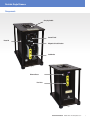
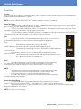
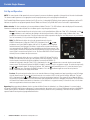
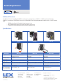
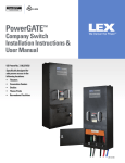
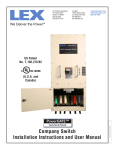
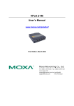
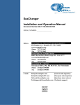
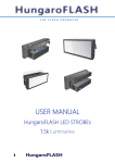
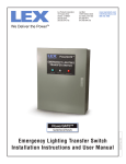
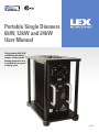
Portable Single Dimmers
6kW, 12kW and 24kW
User Manual
The Lex Products 6kW, 12kW
and 24kW portable dimmers
comprise a unique portable
dimming solution that can be
used individually or as part of
a dimming system.
LM-FD1
Portable Single Dimmers
Contents
Important:
2
This manual contains information critical to the proper installation
and operation of the Lex Products Single Portable Dimmers. Be
certain to read and understand all instructions prior to installation
and operation.
Table of Contents
3Components
4Introduction
4
Safety Notice
5
Installation
6
Set-Up and Operation
7Maintenance
7Troubleshooting
7
Technical Support
8
Additional Resources
8Specifications
2
Contact Lex Products: 800.643.4460 [email protected]
This manual is furnished exclusively to support installation and
operation of the Lex Products Single Portable Dimmers. All concepts
and ideas are the sole property of Lex Products and are not to be
duplicated or utilized in any manner without written permission.
This manual refers to models:
FD1-6K
FD1-C-6K
FD1-12K
FD1-C-12K
FD1-24K
FD1-C-24K
Portable Single Dimmers
Components
Carrying handle
Control Panel
Heatsink
Magnetic Circuit Breaker
Load Outlet
Fig. 1
Dimmer Reset
Line Inlet
Fig. 2
Contact Lex Products: 800.643.4460 [email protected]
3
Portable Single Dimmers
Introduction
The Lex Products Single Portable Dimmers comprise a unique portable dimming solution that can be used individually or as part of a dimming
system. This product range is ideally suited for:
- Motion Picture Production
- Television Production
- Studio Use
- Location Shoots
Features and Benefits of the 6KW, 12KW and 24KW portable dimmers:
- Works as a dimmer or an on-off relay
- Fully digital, push button level setting control as well as traditional slider for setting control level
- DMX512-A control through 5-pin XLR input and thru
- Digital display shows the selected dimmer level from 0-100%, lamp pre-heat level from 0-25%,
relay assignment / function and DMX512-A address from 001-512
- Separate LEDs indicate operating modes and presence of DMX512-A control signal
- LED indicators show status of circuit breaker and output voltage
- Power fail memory
- Retains dimmer level, pre-heat level, operating mode and DMX512 address even after line voltage supply is removed
- Modular panel incorporating microprocessor-based control electronics
- 100% solid state design for reliability
- 8-bit resolution allows full 256-step dimming control to ensure exact level repeatability
- Magnetic circuit breaker protected
- Voltage regulation maintains dimmer output within 2% despite fluctuations in input voltage
- Panel mount stage pin connectors for input and output or Joy tails/Series 18 cam tails
Introduction
Equipment manufactured by Lex Products are built and tested with safety as a primary consideration. However electrical equipment must be
used with care and installed by qualified personnel. Observe all normal precautions when operating this unit.
- Review all instructions before use and save for future reference
- This product must be properly grounded
- This product is for use in dry locations only
- If operating this unit lying on its side, ensure the heatsink side faces up
- Unplug unit from power before servicing
- Do not modify dimmer or housing in any manner
- Do not drop dimmer, handle with care
Lex Products hereby disclaims any and all liability for any injury or damage caused by the faulty installation or improper operation of this
product, including damage from mishandling.
Note: Canadian versions of the Lex Portable Single Dimmers are also available. These products differ only in the use of
Canadian industry standard Joy and Series 18 Cam-type power connectors. The Canadian versions are not UL Listed.
4
Contact Lex Products: 800.643.4460 [email protected]
Portable Single Dimmers
Installation
Location
Place the Portable Single Dimmers in a ventilated area free of excessive humidity or condensation and accessible only to authorized personnel.
Ambient temperature should be between 0° and 32° C.
NOTE: Turn the circuit breaker labeled “Mains Power” off before making any connections to the dimmer.
Connecting Power
- The FD1-6K dimmer is rated for 6,000 Watts at 120VAC. It equipped with a 60 Amp Stage Pin plug for power input (60 Amp Joy
pigtail in Canada) and is protected by a 50 Amp magnetic circuit breaker.
- The FD1-12K is rated for 12,000 Watts at 120VAC. It is equipped with a 100 Amp Stage Pin plug for power input (Series 18 Camtype pigtail in Canada) and is protected by a 100 Amp magnetic circuit breaker.
- The FD1-24K dimmer is rated for 24,000 Watts at 240VAC. It is equipped with a 100 Amp Stage Pin plug for power input (Series 18
Cam-type pigtail in Canada) and is protected by a 2-pole, 100 Amp magnetic circuit breaker.
Line
- Connect the FD1-6K or FD1-12K panel mounted power input plug (see Fig. 3) to a branch circuit
protected 20VAC, 60Hz power source using a cable that is properly grounded and appropriately
rated.
- The acceptable input voltage range for this unit is 95-130VAC.
- Connect the FD1-24K panel mounted power input plug (see Fig. 3) to a branch circuit protected
240VAC, 60Hz power source using a cable that is properly grounded and appropriately rated.
- The acceptable input voltage range for this unit is 190-240VAC, so a 208VAC, 60Hz power
source may be used.
- When the power connections are secure, the dimmer may be energized by turning on the
Mains Power breaker.
- Should the breaker trip, check the power source and cables being used before resetting.
- Do not power any of the units from a dimmed circuit.
Fig. 3
Load
- All Portable Single Dimmers can control incandescent and inductive loads including lamps,
fans and magnetic transformers in the dim mode. In the relay mode, it provides a full sine-wave
output and can control additional load types. Be sure to include transformers in load calculations.
NOTE:
- Care must be taken to assure that non dimmable loads are only operated in the relay mode.
- The Mains Power circuit breaker should be switched off before connecting the load.
- Set the control output to zero or a pre-heat level before energizing the load.
- Plug load(s), up to the capacity of the dimmer, into the power output receptacle using properly
grounded and appropriately rated cables.
Connecting Control Wiring
Fig. 4
- For control using DMX512-A data protocol, plug control cables constructed for this use into the
5-pin XLR connectors (see Fig. 5) labeled “DMX512 In” and “DMX512 Thru” (if cable run continues beyond this unit)
- DMX512 rules require the use of a plug-in terminator on the last unit in a DMX daisy chain. The termination plug should be
plugged into the “DMX512 Thru” receptacle.
NOTE: FD1 units are not self-terminating.
Contact Lex Products: 800.643.4460 [email protected]
5
Portable Single Dimmers
Set-Up and Operation
NOTE: The control panel will be operational once main power is present to the dimmer, regardless of the position of the main circuit breaker.
This feature enables operators to set appropriate control output parameters prior to energizing the dimmed load.
Each Portable Single Dimmer operator interface (see Fig. 5) consists of a three-digit LED display, three momentary pushbuttons and four LED
indicators to report the set-up/operating mode selected. Modes are: Manual, Relay, DMX and Pre-heat. Each mode is explained below.
Mode selection: To select a mode press the center pushbutton labeled “Function.” The LED indicators above the display will incrementally
illuminate to indicate the mode selected. Press the button again to step through each function:
Manual: The manual mode allows the unit to be used as a self-controlled dimmer. When the “Man” LED is illuminated, use the
and
pushbuttons to raise and lower the lighting to the desired level from 0 to 100% output voltage. A 60mm slider is also
provided to set a desired output level. The percent output level will be reported on the display. over-riding any pre-set (push button)
level. to increment by 1% use push buttons (highest takes priority).
DMX: The DMX function allows the unit to be operated remotely using the
DMX512-A data protocol. When the “DMX” LED is illuminated, use the
and
pushbuttons to assign a DMX512 address (001 to 512). The address will be displayed
and held in memory until changed. The dimmer’s output will be a square-law dimming
curve proportional to the DMX512-A control signal being received at any moment. If the
control signal is removed or interrupted, the unit will hold the last level received until the
control signal is restored or until power is reset. The Green DMX DATA LED will illuminate
with the presence of data at the input connectors.
Relay: The relay mode allows the user to switch any 120VAC (FD1-6K and FD1-12K) or
240VAC (FD1-24K) fixture or device (up to the capacity of the unit) on and off. The relay
Fig. 5
function may be controlled locally by the pushbuttons or remotely via DMX512. To
activate the relay mode, when the “Relay” LED is illuminated, press the
pushbutton once to turn the function on and enable
remote control. The display will indicate the DMX512-A address to which the unit is assigned to respond. To switch the relay locally,
press the
pushbutton again. The display will indicate “ON” and the load will immediately turn on. To switch the load off, press
the
pushbutton once, returning to the DMX512-A address. Press the
pushbutton again to turn off the relay function
entirely. When turned off, the display will be blank.
Pre-heat: The pre-heat function allows the user to warm the filament of a large incandescent lamp by providing a small AC voltage
from the dimmer output. The level for this function may be set to a value of 0-25% of the input line voltage. When the “Pre-heat”
LED is illuminated use the
and
pushbuttons to assign the preferred pre-heat level. Then return the unit to Manual, DMX or
Relay mode for operation. The Pre-heat level will remain at the programmed level unless changed by the operator. The Pre-heat LED
will remain illumi¬nated to remind the user that there is a Pre-heat level is assigned in memory. To remove this level, visit Pre-heat
mode once again and use the decrease button to set to 0.
Operating: Before operating the dimmer, check to see that the Mains Power circuit breaker is on. When the dimmer is in manual mode it
will ignore any DMX512 signal that may be present. For remote operation, be sure the unit is in Relay or DMX mode and that a valid DMX512
control signal is present. The dimmer is designed with power-fail memory. When the unit is powered up, it will return to the last mode of
operation and will retain previously programmed information.
6
Contact Lex Products: 800.643.4460 [email protected]
Portable Single Dimmers
Maintenance
The Lex Products Portable Single Dimmers are designed to be low maintenance; however, several precautionary steps will prolong the life of
the electronic components.
- Whenever possible, limit the unit’s exposure to high ambient temperatures.
- Take care not to drop the device and always protect the controls and connectors from damage.
- Do not allow liquid of any kind to enter the unit.
- All screws and connections should be checked, and tightened if necessary, on a regular basis, especially in rental and location
applications.
- If the unit accumulates dust, disconnect it from power and clean it using compressed air.
- Always disconnect dimmer from power before performing any maintenance operation.
Troubleshooting
If the portable dimmer does not operate as expected:
- Check the power source and check all cables and connectors.
- Be sure the Mains Power circuit breaker is on.
- Confirm that the controlled load operates from a constant power supply.
- Confirm that any remote console is sending valid DMX512-A data.
Control indicators do not illuminate:
- Confirm that power is present to the unit.
Inc and Dec buttons do not raise and lower the lighting level:
- Make sure the dimmer is in Manual mode (press and hold Function button until Manual LED illuminates).
Unit does not respond to remote DMX512 input:
- Check all control cabling and check that DMX Data LED is illuminated to indicate presence of control signal.
- Make sure that dimmer is in DMX or Relay mode (press and hold Function button until one of these LEDs illuminates).
Connected load switches on and off instead of dimming:
- Confirm that Relay mode is activated.
- Press and hold Function button until Relay LED illuminates.
- If a DMX512 address is displayed, Relay function is active.
- To deactivate Relay function, press Dec pushbutton. Display should go blank to indicate a return to dimming operation.
The dimmer does not respond to the user controls – Inc, Function, Dec:
- Reset the electronics by pressing the Reset button on the rear of the unit.
Connected load is ghosting and will not shut off:
- A pre-heat level has been set and is retained in memory.
- Cycle the Function button until the pre-heat LED illuminates and use the Dec button to reset the pre-heat level to zero.
- Use the Function button to return to Manual or DMX mode.
Load is stuck on and does not dim or switch off:
- Check to see if Relay mode is activated and the relay has been turned on manually.
- Press and hold Function button until Relay LED illuminates.
- If the display shows “ON” the relay has been turned on manually.
- Press the Dec button to turn the relay OFF.
- If the load remains on, the power device may have failed. Contact Technical Services at 1.855.LEX.1002
Technical Support
The staff at Lex Products is willing and available to help in any way possible. If you have questions or need technical advice or suggestions
regarding this product, please contact Lex at 1.855.LEX.1002 or e-mail Lex at [email protected]. Business hours are Monday through
Friday, 8:30 am – 5:00 pm. In addition, Technical Services is available 24/7 via phone.
Contact Lex Products: 800.643.4460 [email protected]
7
Portable Single Dimmers
Additional Resources
For additional information regarding the DMX512 control protocol, properly known as “ANSI E1.11 - 2004 Entertainment Technology DMX512-A - Asynchronous Serial Digital Data Transmission Standard for Controlling Lighting Equipment and Accessories” visit the following
sites:
- ANSI (American National Standards Institute), www.ansi.org
- USITT (United States Institute for Theatre Technology), www.usitt.org
- PLASA (Professional Lighting and Sound Association), www.plasa.org
Specifications
Catalog No.
FD1-6K
FD1-12K
FD1-24K
FD1-C-6K*
FD1-C-12K*
FD1-C-24K*
Description
Single channel 6,000 watt, 120 VAC,
portable dimmer/relay
Single channel 12,000 watt, 120 VAC, portable
dimmer/relay
Single channel 24,000 watt, 240 VAC, portable
dimmer/relay
Input Voltage Range
95-130 VAC
95-130 VAC
190-240 VAC
Minimum Load
50 W
50 W
50 W
Maximum Load
6kW
12kW
24kW
Overcurrent Protection
Single Pole, 50 Amp magnetic circuit breaker Single Pole, 100 Amp magnetic circuit breaker
Double Pole, 100 Amp magnetic circuit breaker
Cooling
Passive
Passive
(2) 26dB “A Curve” SPL fans (very low noise)
Weight
30 lbs. (13.6 kg)
32 lbs. (14.5 kg)
32 lbs. (14.5 kg)
Dimensions (including
protective top & bottom)
16”W x 8 3/4”D x 14”H
16”W x 8 3/4”D x 14”H
16”W x 8 3/4”D x 14”H
* Not UL Listed
Lex Products Corporation
15 Progress Drive
Shelton CT 06484
203.363.3738
203.363.3742 Fax
LP-FD1 REV.001
Lex West
11847 Sheldon Street
Sun Valley, CA 91352
818.768.4474
818.768.4040 Fax
www.lexproducts.com
[email protected]
800.643.4460
© Copyright Lex Products 2013
Produced in the United States of America
All Rights Reserved.
Lex Products logo and lexproducts.com are
trademarks or registered trademarks of Lex Products
in the United States, other countries, or both.