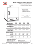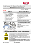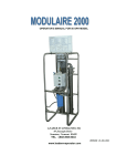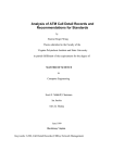
1
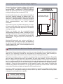
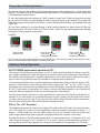
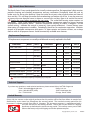
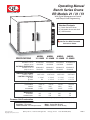
Operating Manual
Bench Series Ovens
ER Models 21 / 31 / 51
Quincy Lab, Inc.
With Digital Microprocessor Control
and Ramp & Soak Programming
Quincy Lab, Inc.
Standard Contents
Process
Set
o
*
*
*
o
Verify C or F units
Increase Setpoint
Decrease Setpoint
(PRESS)
(3 sec.) Enter/Exit
Menu Levels
(1) Bench Series ER Oven
(2) Adjustable chrome wire shelf
(4) Shelf brackets
PROGRAMMABLE CONTROL
Heat cycle
LIGHT
POWER
LIGHT
POWER
LIGHT
HEATER
HEATER
SWITCH
SWITCH
Heat cycle
LIGHT
POWER
LIGHT
POWER
LIGHT
POWER
POWER
LIGHT
LIGHT
Not For Use With Flammable
Solvents or Gases.
POWER
LLDSFKGLS
LIGHT
SPECIFICATIONS
INTERIOR DIMENSIONS
INCHES W x H x D
(CM) W x H x D
EXTERIOR DIMENSIONS
INCHES W x H x D
(CM) W x H x D
TEMPERATURE RANGE
Ambient + 25F to:
CONTROL STABILITY
@ 100C
@ 200C
STANDARD ELECTRICAL
VOLTS/AMPS
WATTS
PLUG/NEMA
WEIGHT(lbs)
SHIPPING
STAND ALONE
Common Unit Construction
MODEL
21-250ER
MODEL
21-350ER
MODEL
31-350ER
MODEL
51-550ER
25.5x20x24
64x50x60
25.5x20x24
64x50x60
25.5x30x24
64x76x60
25.5x20x22.5
64x50x57
33x24x35.5
83x60x90
33x24x35.5
83x60x90
33x34x35.5
83x86x90
33x24x35.5
83x60x90
300F/150C
450F/232C
450F/232C
550F/287C
+/- 2.0 C
NA
+/- 2.0 C
+/- 2.5 C
+/- 2.5 C
+/- 3.0 C
+/- 3.0 C
+/- 3.5 C
120/8.75*
1050
5-15P*
120/16*
1920
5-20P*
120/16*
1920
5-20P*
230/12.5
2850
6-20P
185
165
185
165
225
200
195
170
* Standard models voltage only, optional voltage available. See page 2.
Exterior: Powder Coated Steel
Insulation: Fiberglass
Thermo-control: PID Microprocessor
Issue A Rev 0908
Copyright Quincy Lab Inc. 2008
Interior: Aluminized Steel (stainless optional)
Motor: Sealed Ball Bearing
Heater: Resistive-Tubular Incoloy
Quincy Lab Inc. 1925 N. Leamington Ave.
Chicago, Illinois
1-800-482-HEAT (4328)
PAGE 1
Safety Precautions
Read Operating Instructions Thoroughly Prior to Operation
The Bench Series ovens are not designed for use with any flammable solvents or gases or for
materials that may contain flammable solvents or gases. Use only a grounded outlet that is rated
for your model's electrical requirement - do not use with an extension cord. Oven exterior walls
and doors may become hot to the touch when operating at higher set temperatures. Do not
operate the oven in close proximity to any flammable solvents, gases or materials. Do not leave the
oven unattended during operation, especially when processing materials that have flash point
temperatures lower than the model oven's maximum operating range. Do not operate or modify
the oven to operate without the motor or fan/blower. Conduct periodic maintenance as required.
Set-Up & Installation
Locate the oven on a suitable, clean, solid surface and maintain a minimum of 6 inches of air space
between the rear electrical cover and any building or vertical surface (FIG. 1). This is important as
ambient air must circulate freely through the rear air intake ports for proper cooling of the blower
motor.
Do not cover or restrict air flow at the rear air intake ports, this will cause the motor to
overheat, shortening the motor's life and increase risk of fire. Heated exhaust air is expelled through
the two small ports located just above rear electrical cover. (FIG. 2) Keep materials or building
surfaces that may be susceptible to this heated exhaust air clear from rear area. Maintain a
minimum 5 feet of unobstructed space above the oven to allow exhaust air to naturally convect up
and away from the air intake ports. Keep 3" of air space at the oven sides (3" from control panel
cover). For units with optional Exhaust Chamber Adapter, see page 3.
REAR VIEW AIR FLOW
CLEARANCE
REQUIREMENTS
EXHAUST AIR
6" minimum from wall to
rear blower housing.
10"
FIG. 1
INTAKE AIR
WALL
6"
FIG. 2
Electrical
Plug the unit into a grounded outlet for your unit's rated voltage. IMPORTANT See electrical label
at right side rear electrical cover to verify your units power requirements. Isolate each model to a
separate appropriately rated circuit or breaker. Below are the NEMA plug configurations that are
supplied with the various Bench Series ovens. These configurations will also help to identify the
ovens electrical rating or power requirements.
230 Volt Units
120 Volt Units
15AMP
5-15P
20AMP
5-20P
15AMP
6-15P
20AMP
6-20P
PAGE 2
Connecting to the Exhaust Chamber Adapter (Optional)
Connect the exhaust chamber adapter with standard
3" or 4" diameter single or double-wall steel or
galvanized pipe. A minimum of 4 inches of clearance
should be maintained between the connected pipe
and any building surface or material. (FIG.3)
4" minimum from wall
to rear exhaust piping.
4"
WALL
For best performance, run a short pipe horizontally (3
feet max.) directly through an exterior wall. For
vertical runs the exhaust pipe should not have more
than one (1) 90 degree elbow, a maximum horizontal
run of 3', and a maximum of 15' vertically. Exceeding
these recommendations may cause improper
ventilation.
CLEARANCE
REQUIREMENTS
Poor exhaust quality would be indicated by an excess
of fumes and/or vapor from around the door gasket
versus what would normally be present if no exhaust
venting was used.
Piping run lengths can be extended beyond
recommended maximums where a connection to an
existing ventilation or exhaust system provide a larger
pipe diameter and/or a mechanically powered draft
that provides a negative pressure at the point of
connection.
FIG. 3
Mechanically powered vent systems work best to
eliminate fumes and moisture vapors, but depending
on vacuum strength at the point of connection, it may
slightly reduce the oven's time-to-temperature and
recovery performance.
Important Note about the Exhaust Chamber and Connection
The optional exhaust chamber adapter is used to vent oven chamber fumes and heated moistureladen air to a building's exterior for the purposes of minimizing excess heat, humidity or
unpleasant but otherwise harmless fumes within an interior working environment.
The exhaust chamber system as a whole is not designed for use to remove harmful or flammable
gases or vapors since the oven itself is not rated for use with such materials. Also, the oven, being
electric as opposed to gas, does not produce any harmful bi-products in the process of producing
heat. It is recommended that the attached exhaust chamber and piping be checked once a year for
any obstruction from dust, dirt, or material process "plaque" build-up from processing certain
materials. Check with the manufacturer of the materials used in your process if heating the
material may produce a bi-product or out-gassing that may build up on the interior surface of the
oven, exhaust chamber or piping and present a fire hazard over time.
Contact an HVAC engineer for assistance with installation or questions regarding proper venting
requirements in your specific building or location and if any local or national fire or safety codes
may apply for your application or process.
Annually check exhaust
piping a for possible obstruction
or material process build up.
PAGE 3
Shelve Installation and Use
Install adjustable shelf by first placing the shelf bracket rivets into the corresponding keyhole
supports located on each inner side of the oven. Orientate the bracket in the "down" or " L" position.
This position guides the shelf in and out and protects the side wall from being scratched. The bracket
may also be place in the "up" or " " position if
slightly more interior clearance is needed. Place
the shelf on the brackets as shown. (FIG. 4)
Each shelf will support a distributed load of 100
lbs. maximum. Do not exceed a combined total
of 300 lbs. within the oven at one time. Avoid
placing articles on the oven floor. Instead, use a
shelf at the lowest adjustable position.
Care should be taken when removing articles
from the oven. Don't pull the shelf out when
removing heavy loads. The shelf is not secured
and loads can tip and fall forward.
FIG. 4
General Operation
All control parameters and other control variables have
already been factory set for your model's temperature range
and capacity to provide heating and performance
characteristics for a broad range of applications. Your Bench
Series ER oven is ready for operation.
To power the oven, turn on the power fan switch. The blower
will begin to circulate chamber air and the temperature
control will display the current chamber temperature (green
LEDs) and a factory set temperature (orange LED's) of 125
degrees F. Turn heater switch to heat. The heat cycle indicator
will illuminate and the oven will immediately begin heating
towards the set temperature. Once the set temperature is
reached, the heat cycle indicator will cycle on and off with the
heaters, maintaining the set temperature. Typically, the oven
will need to cycle at set temperature for a minimum of 20
minutes before it will achieve equilibrium and become
temperature stable (see stability specs. on page 1).
To change the set temp, press and hold the star key then
press the up or down arrow keys to change to the desired set
temperature. Pressing the star key
alone verifies the
control's temperature display units in degrees F or C (factory
set at "F" for Fahrenheit). To change the display units to read
in Centigrade, see the control's Menu Level Functions page 6.
*
*
DIGITAL MICROPROCESSOR
Temperature controller
*
Temperature Setpoint
Actual Chamber Temperature
Heat Cycle Indicator
To adjust temperature set point
press and hold the star key
then press:
*
To Increase Setpoint
To Decrease Setpoint
The temperature setting is maintained in the control
whenever the power is turned off. When the oven is turned
back on it will begin heating toward the temperature setting.
PAGE 4
General Operation (continued)
The heater switch in the off or cool position allows for convenient ambient air
drying of articles or to more slowly & evenly cool heated articles without
having to lower or change the temperature setting. Also, use this switch to
allow the oven to cool before turning the fan off when using the oven at
higher temperature settings. This helps to both cool the motor (prolonging
it's life) and remove any moisture laden air before it condenses in the
chamber, which will help prevent premature corrosion over time.
HEAT
FAN/COOL
HEATER
SWITCH
Chamber Loading
Load the oven so that air circulation within the oven is not impaired. Note the air flow from the
top section view (FIG. 5). Heated air flows from back to front along the side walls, then moves
horizontally toward the chamber center and back toward the recirculating blower. Placing an
article against the side walls or rear blower return vent opening will greatly affect unit
performance i.e. chamber uniformity, run-up & recovery, maximum operating temperature and
energy use efficiency.
Here are some guidelines that are critical to optimum oven performance and better/faster work
load processing.
Leave a space between articles on a shelf.
TOP VIEW AIR FLOW
(SECTION)
For best processing performance for a single
item, adjust one shelf so that the article is
centered in the oven.
BLOWER MOTOR
Avoid placing articles on the oven floor.
Instead use a shelf at the lowest adjustable
position.
Do not place articles against the inner side
walls or the slotted vents in rear air plenum.
This will obstruct air flow and degrade
uniformity.
Do not overload the unit with large or highdensity loads. This will show by non-uniform
processing and/or long heat-through or
processing times.
FIG. 5
PAGE 5
Menu Level Functions
FUNCTION PROMPT
Access the menu levels for the following functions: (all user-applicable functions
and their menu locations are outlined in red in Menu Guide below).
~
~
~
~
~
~
Change control to read in C or F temperature units ( UNIT in level 2).
Change to whole degree or 1/10th degree display resolution ( DISP in level 2).
Run or Read temperature tracking /data ( CHEK or READ in level 3).
Lock Temperature setting against inadvertent adjustment ( SP.LK in level 1).
Calibrate control temperature to an external standard ( ZERO in level 3).
Auto Tune PID performance parameters ( TUNE in level 1).
\\
*
FIG. 3
To access the menu levels:
Press and hold both arrow keys until the "tune" / "off" function prompt is displayed from within LEVEL 1.
When in the function menu the LED display will alternate the function prompt with the current function setting
when keys are released. See "menu entry point" in Menu Guide below.
To navigate within the menu:
Press the down arrow to move "Left" into menu LEVEL SELECTION ( LEVL 1 level 1) (FIG 3). Use up and
down arrow keys individually to move "right" or "left" within a level. Hold star key and up or down arrow keys
to move "up" or "down" through levels 1, 2 and 3.(Note: you must be at LEVL 1 prompt to move up/down thru
levels)
To change the function setting (or to read function data - if a read only function):
Once at the desired level function prompt, press and hold the star key and press the up or down arrow key to
change a function setting or to read alternate function data. Release star key to set the function. Press and
hold the up and down keys together to return to temperature display, or control will auto-return in 60 seconds.
LEVL 3
SP1.D SP2.D BURN REU.D REU.L SPAN ZERO CHEK READ TECH
(PRESS)
SAFETY SETTINGS
RELAY OUTPUT TYPE
CONTROL CALIBRATION
,B
ar
,P
Si
,P
h
*
LEVL 2
SP1.P HAND
(PRESS)
PL.1
PL.2 SP2.A SP2.B DISP HI.SC LO.SC INPT UNIT
\\
MANUAL ADJUSTMENTS
*
AUDIBLE/ALARM MODES
TUNE BAND INT.T DER.T
LEVL 1
DAC CYC.T OFST SP.LK SET.2 BND.2 CYC.2
PID AND PERFORMANCE SETTINGS
(PRESS)
MENU ENTRY
POINT
*
Press star key & up
or down arrow key
to scroll through
functions levels
LEVL P
RESOLUTION, RANGING, INPUT AND UNIT SELECTION
A
(o uto
FF T
), un
on e
, P Fu
Ar nc
k, tio
0. P
At n
1 ro
,S
to po
P
(1 10 rti
7) 0% on
or
al
o
au f s Ba
to en nd
-t
s
of Inte une or m
f, gr
v
o
(5 r 0 al T aria ax
.0 .1 im
tio
)o t
n
r a o 6 e (r
ut 0 es
m
o
e
of Der -tun inu t)
f, iv
e te
o a
(5 r 0. tive var s
0) 1
ia
T
t
or o im tion
au 20 e (
to 0 s ra
De -tun eco te)
e nd
riv
va s
at
ria
ive
(2
tio
.5 Co Ap
n
), nt p
0. ro ro
5
a
l
ch
to
C
on yc
5.
0
.o le
f,
or Tim
0. e
1 or
(2 to on
0) 81 /o
O
se ff
ffs
co
(0 et
nd
), (m
s
0
a
to nu
5
In 0 a
t.t % l r
e
=
of x ba set)
Se
f
nd
tp
oin
tL
(o oc
FF k
), Fun
Ad
on c
jus
tio
SP t a
n
2 lar
co m
(0 n s
) , fig et
1 ure po
SP to d a int
fu s if
2
Ba ll sc ala
al rm
nd
(
0
of .2 / G e
se ) 0 ai
n
ns .1
or to / H
fu 10 yst
ll s 0 .
SP
ca %
2
le
(o Cyc
n.
l
of e o
),
n
/
or
o
0. ff
1
to
81
Press up & down
arrow keys to
scroll back-andforth through
level functions
(PRESS)
*
UER RSET
TEMPERATURE TRACKING
Re
a
va d he
rie at
s e
re 100 r ou
ad % tp
on to ut %
Se
l
0%
"h t SP y
ea 1
te m
r" an
(1 u
00 al
)% ou
Lim
to tpu
0% t
it h
e
a
(1 te
00 r
)% ou
to tpu
0% t %
Se
tS
(1 P2
00 o
)% ut
to put
0% %
Co
nf
i
no gur
ne e m
,(
dV ain
.h mo
Co
i),
nf
... de
.F
igu
S.
no re
hi,
ne Se
...
,L
co
tC
nd
H,
m
ho od
Di
ld,
e
sp
(L
lay
t.h
o)
(1 Re
) o so
r 0 lut
ion
Se
.1
de
tT
gr
e
ee
(3 mp
25 er
,4 atu
50
re
,5
50 ma
Se
)F xs
tT
pe cal
em
rm e
pe
od
ra
el
tu
re
(5 min
0)
Th
s
F
ca
er
le
no mo
ne co
u
,(
p
l
J)
, k e Ty
, l,
p
r, e
s,
Se
t,
NO
rtd
lec
NE
t o
, o
C, o C / o
(
F
F)
(PRESS)
(PRESS)
A
(re dv
ad an
on ced
lr A
/ s ut
ee o T
m un
So
fg e
s D
ftw
m at
a
an a
(re re
ua
ad Ve
l)
r
on si
Co
ly) on
(D nt
r
o ol
No R
t R ese
es t
et
)
Co
nt
r
va ol C
rie al
s: ibr
(-3 ati
.0 on
A
to
3. dju
0)
st
Functions Menu
Guide
le
l)
)
ts
r
ca
er
na
ul
s i
ito
u
nt ll s
at
r
ig
es )
2
e
e
s
2
D
.
.
(
on
h G
t d
fu
.2
R
s
E
i
m
t
(
d
t
t
u
y
r
L 1
l
M
t
u 1
s 's
o 1
pu G
g
ito on
ju or
ts 2i,
tp r,
pu nL
n- d,
ut nL
ut A
on d
kin
ur u.2
pu n.
ou .2
Ad ns
O A
O d),
M rea
ut , 1
e , 1r
y sr,
n f se
ac ff)
rb ,1
r
s
o
y
a
s
a
(
g
n
l
o
r
s
d
c
T O
la (s
se i.2
Sp o
ns .s
ve d.2
kin Lo
Re y),
re , (
Re y,
er , 1
or 5%
ac i ,
tu n
Se ), dn
Re ), 1
ry (rl
y , rl
ev n )
ra o
Tr , h
ns to 2
ar ne
da ne,
e
C
R
2
e
d
r
d
n
.
p
S
S 0)
im o
a A
n
r.2
co no
m
.
P.
(1
Pr n
Re V
(1
(0
(u
Te
Se
*
Level "P" is the Ramp
& Soak program level.
See separate Ramp &
Soak Programming
Operating Manual
SP2 AUDIBLE / ALARM SETTINGS
IMPORTANT NOTE: The non-high-lighted control functions
within the menu levels are factory set for the basic and safe
operation of your model oven. Care should be taken when
navigating or changing user-applicable settings, outlined in
red, so as not to alter these factory settings. Factory settings for
each function are listed within the "( )" in each prompt tab above
to use as a trouble-shooting reference.
)
;
s
3A 3d
SP d.
nit
t or
e oP;
or E; 2 3E
eu
oin e
e
e
L
er
typ ; Lo inS
tp scal
2A 3d; 3 ; 2E.
rat 0)
tim
dE tE
alu
e oLd
b
t
e
P
er
v
P
;
0
e
s
l
;
d
n
p
.
p
l
S
m
b
0
E
E
L
;
t
o ;h
rt
Ld PS
m
m
re
alu 15
am (1 e
nu ax
me St dE
am
ut( 2E d.3
ge r fu ale
sta
ilu y m nt
nu 31
t r 90
gra ho Y;
t r 0s
k v to
eg K; P;
nt 6 m
tar so sc
utp 2d; d; 2
m
m
ro n; CoP er fa over t; Co
ac 0.1
e s oA Eo
oin 9 tim just sen full
oin 6
me 12
3
t o E;
gra ; SP
gra 1 to
tp o 9 its/
tp ur;
fin r; S ll;
n p F; o inS;
w rec rSE
ldb F;
Ð
eg 1 to
en non 2E.
Se 1 t un
Ss
Se ho
Ru oF
Ad +/
Pro PV
De SP Ca
Po
Pro
Ho oF
Ev
PROG
RUN FAIL
ST.U SPRU
HB.V
EO.P
RAMP & SOAK PROGRAM SETTINGS
PAGE 6
Temperature Tracking Feature
This feature monitors the stability of the control during any given length process. It will record and
display: 1. The total variation or spread between high and low, 2. The absolute or maximum high and
3. The absolute or minimum low.
To start the tracking feature navigate to "CheK" prompt in menu level 3. Hold star key then up arrow
key to select ON. Return to temp display or control will auto-return in 60 seconds. The control will
track the temperature variation until "CheK" is turned off. Recorded readings are retained until next
"CheK" ON.
You can view readings at any time during or after tracking feature has been turned off. But depowering the unit will reset "CheK" to OFF and "rEAd" to zero. To view total temperature variation
navigate to "rEAd" prompt in menu level 3.
EXAMPLE:
*
*
*
*
Displays total
o
variance (0.9 )
*
*
Press & Hold
Then Press
Once
Displays High Variation
*
*
Press & Hold
Then Press
Again
Displays Low Variation
TIP: To avoid erroneous tracking data from run-up temperatures or door openings, start the Tracking feature after
articles have been placed and temperature steadies at set point.
Advance Control Operation
AUTO-TUNING performance parameters PID:
The control's PID performance parameters as well as other control variables are factory tuned for
your model's temperature range and capacity to provide heating and performance characteristics
for a broad range of applications. For certain applications, such as extra large or high density loads, it
may be necessary to generate new PID parameters to improve oven performance.
To customize performance for a specific application, activate the auto-tune function. At the "tunE"
prompt in the functions menu, change the function setting from "off" to "on". NOTE: To tune
parameters more accurately for set temperatures below 250 degrees F, change the function setting
to "At.SP" (at set point), instead of the "on" setting. Auto-tune will take between 5 and 45 minutes to
complete. When completed it will return to normal operation automatically.
Start the tune function at the point in your application for which you desire better performance. For
example; If you want better run-up performance once a load is placed, start the auto-tune function
just after you've place the load. If you want the best stability after the load achieves temperature,
start the auto-tune function after the load achieves temperature, etc.
PID vs "On - Off" Operation:
The temperature control has two primary modes, PID mode and On-Off mode. The control is factory
set in PID mode. This mode is best for applications requiring excellent temperature stability, +/- 1
degree. On-Off mode can be used where faster run-up and recovery times for batch-style
processing are desired and where a greater cyclical deviation from set point is not critical.
To place the control in On-Off mode, navigate level 1 in the functions menu. Change the "int.t" and
"der.t" function settings to "oFF" and the "CyC.t" to "on.of". Return to the temperature display by
pressing the up & down keys together for 3 seconds. The control will now operate in On-Off mode.
PAGE 7
Periodic Oven Maintenance
The Bench Series Ovens are designed to be virtually maintenance free. But operational safety requires
periodic cleaning and chamber temperature accuracy verification. Periodically check the rear air
intake vents for dirt or dust build-up. Keep the intake & exit ports clear of obstruction and clean of
dust and dirt. This will keep the motor from overheating and reduce risk of fire. It may be necessary
to remove the rear electrical cover to clean or vacuum dirt and dust from in & around the motor.
Unplug the oven before removing the rear cover. The sealed ball bearing motor requires no
lubrication. Twice a year, check the actual oven chamber temperature against a known accurate
temperature measurement device. Maintain temperature accuracy to within 10 degrees F of the
control setting - calibrate the control as necessary (see control calibration). Contact factory upon
observation of temperature instability. Periodically check fan for continuous operation. Maintain
records of all periodic maintenance and repairs. To clean exterior and interior surfaces, use a damp
cloth or with an all-purpose cleaner. Avoid commercially available oven cleaners.
Replacement Components
All replacement components are readily available and are easily replaced in the field.
COMPONENT
MODEL
PART #
COMPONENT
MODEL
VOLTAGE
PART #
301-2235
301-2230
Power / Heat Switch
All Models
301-2251-1
Blower Motor
All Models
120 Volt
230 Volt
Door Ball Catch
All Models
301-2221
Temperature Controller
All Models
120 or 230 Volt
Door Handle
All Models
301-2206
Power Light (red)
All Models
120 Volt
230 Volt
101-2202
101-2202-1
Door Gasket (Per Foot)
All Models
301-2253
120 Volt
230 Volt
120 Volt
230 Volt
301-1210
301-1210-1
301-1212
301-1212-1
Heater
21 & 31-250
Blower/Fan Blade
All Models
301-2218
Heater
21 & 31-350
Shelf
All Models
301-5000
Heater
51-550
230 Volt
301-1213-1
(Galvanize)
(Stainless)
All Models
301-5001
301-5001S
Cord and Plug
21 & 31-250
120 Volt
230 Volt
Exhaust Chamber Adapter
All Models
301-2065
Cord and Plug
21 & 31-350
120 Volt
230 Volt
101-1403
101-1403-1
101-1203
101-1403-1
Stand w/shelf
Cabinet stand
301-2060
301-2055
Cord and Plug
51-550
230 Volt
101-1203-1
Shelf Rail
Floor stand or Cabinet
*Disconnect Power Before Repairing or Replacing any Component
Technical Support
If you have any questions or need technical assistance, please contact Quincy Lab Tech Support at
Email: [email protected]
Voice: 800-482-HEAT (4328)
Fax: 773-622-2282
Quincy Lab, Inc.
1925 N Leamington Ave
Chicago, Illinois 60639
Limited Warranty
Quincy Lab, Inc. warrants to the original purchaser that this product will be free from defects in material and
workmanship under normal use throughout the warranty period. The standard warranty period for this
instrument is eighteen months from date of shipment. The instrument warranty is supplemented with a
two year warranty on the heating element. Please refer to your invoice or shipping
documents to determine the active warranty period. This warranty covers parts & labor
(labor at the factory only) and shipping cost for the replacement parts.
Copyright Quincy Lab Inc. 2007
PAGE 8