1
03 multifunzione GB 2009:digitali
26-06-2009
8:37
Pagina 81
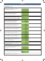
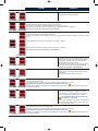
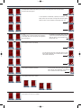
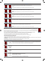
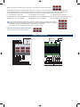
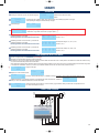
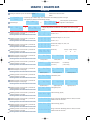
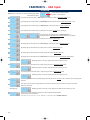
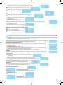
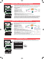
On the further page it is possible to select the parameter to which applies the 1st alarm threshold between:
3U alarm applied simultaneously to the three phase-neutral voltages, where is enough that one of the three voltages exceeds the selected value to activate the alarm
3UF alarm applied simultaneously to the three phase-phase voltages, where is enough that one of the three voltages exceeds the selected value to activate the alarm
3i
alarm applied simultaneously to the three currents, where is enough that one of the three currents exceeds the selected value to activate the alarm
i1
alarm applied to the L1 current phase
i2
alarm applied to the L2 current phase
i3
alarm applied to the L3 current phase
U1 alarm applied to the L1 phase-neutral voltage phase U2 alarm applied to the L2 phase-neutral voltage phase U3 alarm applied to the L3 phase-neutral voltage phase
U12 alarm applied to the L1-L2 voltage phase
U23 alarm applied to the L2-L3 voltage phase
U31 alarm applied to the L3-L1 voltage phase
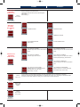
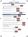
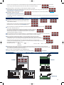
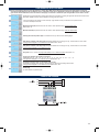
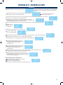
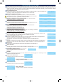
The further page shows also the percentage value of the alarm.It is possible to modify the percentage value of the alarm;
by pressing the front button the percentage is varied with steps of 1%( to fast forward maintain pressure on the front button)
and displayed on the page is the equality between the numerical value and the percentage.
Example: having choosen the parameter 3UF, the percentage 51% correspond to 255V
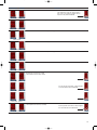
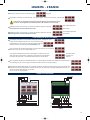
Now the 2nd alarm threshold configuration page appears
Where it is necessary to act exactly as explained above
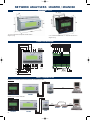
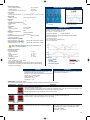
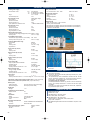
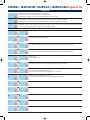
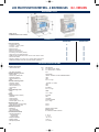
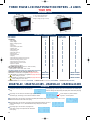
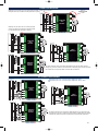
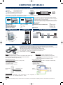
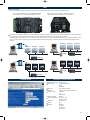
CONNECTION DIAGRAMS
Alarm 2
Alarm 2
V
N
13
17
15
3
4
19
6
7
5A
L1
L2
L3
S1
S2
S1
S2
S1
S2
P1
P2
P1
P2
P1
P2
N
L1
Alarm 1
21 22 23 24
8
230V 50Hz
2
1
0,5A - 100V NA
230V ~ 50 Hz
NA
Alarm 1
C
0,5A - 100V
C
N L
L1
L2
L3
N
1RANM6R
V
5A
S1
S2
S1
S2
S1
S2
P1
P2
P1
P2
P1
P2
N
2RAN96R
81