1
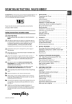
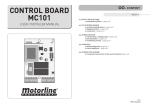
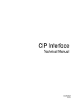
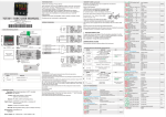
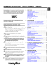
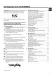
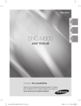
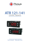
ATR620
20 Introduction
Programmers ATR620 are the results of a wide experience with
applications for temperature and process control by Pixsys
(www.pixsys.net ).
High configurability of both hardware and software resources
allows the installer to configure the controller assuring both userfriendliness for the operator and at the same time the
programming of complex and accurate firing profiles.
To program a cycle means basically to enter couples of values
time /temperaure (setpoint) for each segment of the cycle. Each
controller can be connected to one or two sensors; the output
options include relays and SSR control. Other resources are
available for the management of alarms, auxiliary and digital
commands. Possibility to integrate the unit into supervisory
systems or communication networks is assured by RS485 and
protocol Modbus-RTU with Master/Slave modality.
Memory card allows to quickly copy parameters and cycle data,
keeping record of the different configurations.
**Chapters 26.1 and 27.1 specifically focus on the operating
instructions for the users.
21 Models
The series ATR620 includes two versions: the following table
allows to choose the correct model.
21.1 Ordering codes
ATR620Inputs
2
Outputs
1
2
Power supply
ABC
2 Inputs TC-RTD-V/mA
2 relays + 1 output SSR
3 relays
24/230/115Vac ±15% 50/60Hz
56
22 Technical data
22.1 Main features
Visualizers 4 displays 0,56 inches
4 displays 0,28 inches
Operating temperature 0-45°C, humidity 35..95uR%
Sealing IP54 Frontal, IP30 box, IP20 terminals
block
Material Noryl 94V1 self-extinguishing
Weight 400g
22.2 Hardware data
Analog input 1: AN1, AN2
Software configurable
Input An. 1
Thermocouple K, S, T, R, J, E
RTD type PT100, Ni100
Input An. 2
Thermocouple K, S, T, R, J, E
Input 0-1V, 0-10V,0-20mA, 420mA
Relay outputs 2/3 relays: OUT, A1, (A2)
Configurable for command or
alarm
SSR output 1 output: A2
Configurable for command or
alarm
Accuracy
(25°C)
0.2 % ± 1 digit
for input TC,
RTD , V, mA
Contacts 8A250V~
Output 12Vdc
30mA
Serial input 1: RS485 , Modbus protocol
Digital input 1: IN1, IN2
Configurable as Input START/STOP, signal
, HOLD input
57
22.3 Software data
Control algorithm ON-OFF with hysteresis,
P, PI, PID, PD time proportioning
Proportional band 0...9999°C or °F
Integral time 0...9999 sec (0 excludes)
Derivative time 0,0...999,9 sec (0 excludes)
Software functions Auto-Tuning , configurable alarms
Programmable 15 cycles, max 20 segments (steps) for
cycles each cycle + function “simple controller”
with programmable setpoint
Remote control Setpoint received by analog or serial input
Manual function Increase/decrease manually the percentage
of output (manual control of power)
23 Sizes and installation
58
24 Electrical wirings
Altough this controller has been designed to resist
noises in an industrial environment, please notice the
following safety guidelines:
• Separate control wires from power wires
• Avoid mounting close to remote control switching
systems, electromagnetic relays, powerful
engines
• Avoid proximity of power systems, especially
those with phase control
24.1 Wiring diagram
59
Power supply
24/115/230Vac ±15% 50/60Hz
(selction by internal jumper)
Default selection: 230 Volt
Version ATR620-xxABC
Set SW1 as in the drawing beside to select
proper power supply
Analog input AN1
Thermocouples type K, S, T, R, J, E
•
•
Respect polarity
PT 100
NI100
When extending thermocouples be sure to
use the correct extension/compensating
cable
PT100, NI100
•
•
For a three-wire wiring use cables with
the same diameter
For two-wire wiring, short-circuit
terminals 14 and 15
3
2
1
Analog input AN2
Thermocouples type K, S, T, R, J, E
• Respect polarity
• When extending thermocouples be sure to
use the correct extension/compensating
cable
Signals 0-1V, 0-10V, 0-20mA, 4-20mA
• Respect polarity
60
Signals 0/4….20mA with 3-wires sensor
OUT : 4...20mA
IN :9...33V DC
P :0...100mbar
Pmax :3bar
T :0..70°C
Respect polarity
A=Sensor output
B=Sensor ground
C=Sensor supply
Signals 0/4….20mA with 2-wires sensor
OUT : 4...20mA
IN :9...33V DC
P :0...100mbar
Pmax :3bar
T :0..70°C
Respect polarity
A=Sensor output
C=Sensor supply
Serial or digital input
Configurable as serial input or two digital
inputs
• RS485 Modbus
Relay / SSR outputs
Contact capacity 8A/250V~ resistive
•
•
Configurable as command or alarm
Configurable as N.O. or N.C.
Contact capacity 8A/250V~ resistive
•
•
Configurable as command or alarm
Configurable as N.O. or N.C.
Version ATR620-21ABC:
• Capacity 12V/30mA
Version ATR620-22ABC:
• Contacts capacity 8A/250V~ resistive
Configurable for control or alarm N.O. or N.C.
61
25 Displays and keys
1
5
4
3
2
6
7
9
11
10
12
8
25.1 Numerical indicators (displays)
Visualize usually process value (ex. Value
1
read by thermocouple), but may also
visualize setpoint value, time elapsed after
cycle start1 , step number2 , percentage
value of output , value of entering parameter
GREEN
during configuration 15.
Visualization on this dispay is programmable
2
and may be chosen as setpoint value,
elapsed time or step/cycle in progress.
Visualize number of entering parameter
during configuration. VisuaIize Step-time
RED
(ex.:01-T) or step-setpoint (ex.:01-S) which is
being entered during cycle programming.
1
Example
for 1 hour, 5 minutes
2
Example
See chap.26
for step no. 3
15
62
25.2 Leds
ON when output OUT is active
3
4
ON when output A1 is active
5
ON when output A2 is active
6
ON with cycle in progress, flashing if function “Simple
controller” in progress, remote setpoint, manual control,
serial communication.
25.3 Keys
•
7
•
•
•
8
9
•
•
•
•
•
•
•
•
•
•
10
•
•
11
12
Scroll or modify parameters during configuration
Scroll available cycles (to start or modify)
Modify time or setpoint values when programming cycles
Modify setpoint when function “Simple controller” (TERM)
is working
Fast advancement with cycle in progress
Scroll or modify parameters during configuration
Scroll available cycles (to start or modify)
Modify time or setpoint values when programming cycles
Modify setpoint when function “Simple controller” (TERM)
is working
Fast go back with cycle in progress
Visualize duration of latest completed cycle if controlIer is in
STOP mode
Second process only if enabled
Scroll flashing digit to modify values during configuration of
parameters
With cycle in progress, visualize (cycling) setpoint value and if
configured also other data.
Enter list of available cycles or configuration mode when the
controller is in STOP mode
Press it for more than 1 second to enter functions menu with
cycle in progress
• Start new cycle or stop cycle in progress
• ESCAPEkey when the controller is in configuration mode
• Confirm entered value or selected function
63
26 Programming and configuration
There are two different levels of programming :
1. Programming of cycles (for operator/user) means entering of
time/setpoint values for each step/segment of cycle.
2. Configuration (for manufacturer/installer of plant) means entering
of basic parameters (sensor type, outputs functioning, operating of
auxiliary output ..).
26.1 Programming (or modifying) cycle data
With or without starting setpoint, with or without timed
auxiliary outputs ***
***The above specifications underline the possibility given to the
installer (plant’s manufacturer) to choose the sequence of
operations required for the programming of a firing cycle.
This paragraph includes all available options. In case that the
installer decides to chose a simplified programming with less
options, it is highly recommended to prepare additional/separate
instructions specifying only the selected sequence. The file of this
paragraph is available in the Download section at www.pixsys.net
and it may be used for this purpose.
Set the controller to
Press
1
mode and follow the points below
Display
Red
display
Do
shows
.
2
Increase or decrease to
visualize visualizzare
for cycle no.1
up to
15.
64
for cycl no.2
for cycle no.
26.1.1 Programming of starting set-point (if configured)
Press
3
Display
16
4
16
Do
Red display shows
, then At any time press
to quit the programming
mode and save
(see configuration of
th
modified data..
visualization Par.19, 4
digit).
Green display shows the
“starting setpoint”.
Otherwise go to point 5.
Increase/decrease value on Enter starting setpoint
green display.
(ex. Temperature at
cycle start)
or
The first two digits indicate number of step. Last digit shows
entering the
time value/duration of step or
entering setpoint value (ex.:temperature value
to reach within the programmed time)
65
26.1.2 Cycle programming (programming of steps/
segments)…
Press
5
6
Display
Do
Red display shows
or number of step which is
being modified (for a few
seconds), then
.
Red display shows time
value (duration) of step.
Increase / decrease the
value on green display
N.B.:Max. 20 steps can be
programmed for each cycle.
Then the controller
automatically goes to point
12.
7
Red display shows
or number of step which is
being modified and then
.
Green display shows
setpoint of step
(temperature to reach within
the selected time)
66
Enter duration of step
as hours:minutes
** Enter
for endless time or
enter
for cycle end (in case
that not all available
steps are required) and
skip to point 12.
Use arrow keys
+
to enter setpoint
value (temperature
required at end of each
step)
26.1.3 Programming of auxiliary output (if configured)
Press
8
Display
Do
Green display shows
or
.
9
If output A1 is not
programmed as timed
auxiliary, go to point 10.
Select the state of
auxiliary output during
the step:
for
active or
active
10
Green display shows
or
.
11
for not
If output A2 is not
programmed as timed
auxiliary, go back to
point 5
Select the state of
auxiliary output during
the step:
for
active or
for not
active .
Go back to point 5.
26.1.4 End of programming…
Press
12
Display
Do
The controller returns
to STOP mode,
storing the
programmed cycle.
Red display
shows
.
67
In case that outputs (A1, A2)
are programmed as
auxiliaries, repeat points 9
and 11 to program the state
of outputs after cycle stop.
27 Start of a cycle
27.1 Cycle start and programming of delaied start
Red display shows
Press
1
.
Display
Red
display
available cycles
Do
shows
2
Increase or decrease
until the chosen cycle is
visualized
(for cycle no.1),
(for cycle
no.2)...
3
Cycle
starts.
Buzzer
Green
display
or rings.
shows process value, red
display shows the value
which has been selected
on P-51, 1st digit
If function “Delayed start” is enabled (see P-01, 2nd digit)
follow the table below
4
Red
display
shows
or
, green display
shows
flashing
the
programmed time.
5
Increase or decrease the
waiting time after cycle
Start (Hours:Minutes).
6
Start of waiting time. At
elapsing of programmed Press
time value
time, cycle will start..
68
to modify
27.2 Function “Fast advancement”
During cycle execution or in case of restart after an interruption, it
may be useful to change the programmed time value of the
running cycle (onwards or backwards) to meet the required
setpoint.
Press
1
Display
Do
Forwards or backwards on To stop the cycle and set
cycle (each beep of
the controller in
internal buzzer means one mode before end of cycle
minute).
press
.
27.3 Function SIMPLE CONTROLLER17 with cycle in
execution
This function can be activated during cycle execution.
Press
Display
Do
1
Red display shows
Keep pressing the key
for approx. 1 second.
2
flashing.
Red display shows
3
. The controller
activates the output to hold
the programmed
temperature
Modify setpoint value. Red
To quit the function press
display shows
and
green display shows new
(the controller returns to the
setpoint for a few seconds. the cycle which was
previously in execution).
17
nd
Access to this function can be denied to the operator on P-01, 2 digit
69
27.4 Function SIMPLE CONTROLLER in STOP mode.
Set the controller to
Press
1
mode.
Display
Do
Red display shows
available options
2
3
4
5
6
Increase until
visualized
is
Red display shows
, Green display
shows setpoint value.
Increase or decrease
Enter required setpoint
setpoint value
value.
The controller activates
the output to hold the
programmed
temperature..
Values are visualized
cycling.
To modify setpoint
press
and/or arrow
keys (again
and arrow
keys for
)
To quit the function press
.
70
27.5 Auto-tuning
Auto-tuning18 function can be started if the controller is configured
as SIMPLE CONTROLLER.
Process value must be at least 35% lower than setpoint value
(to avoid overshooting of temperature above setpoint value). If two
process are enabled, please go to P-19/1st digit, to choose the
process to which Autotuning will refer.
Press
Display
Do
is flashing on red Keep pressing for 1 second.
1
display.
Red display shows
2
The controller starts the
self-calibration cycle
Wait until the writing
disappers. To stop the
function before it is
completed, press
.
27.6 Activate remote setpoint by input 2 19
Set the controller to
Press
1
mode and follow the points below.
Display
Do
Red display shows available
options.
Increase or decrease until
2
is visualized
3
Green display shows process To quit the function press
value. The controller activates
control output.
18
nd
Access to this function can be denied to the operator on P-01, 2 digit
th
To configurate this function, select 0 (remote setpoint) on 4 digit of P-01
th
and “ Remote setpoint by analog input AN2” on 4 digit of P-05.
19
71
27.7 Activate remote setpoint by serial input20
Set the controller to
mode.
To start the function by serial input, write 1 at modbus address 15:
this operation must be repeated at least every 8 seconds,
otherwise the controller will return to
mode
To quit the function write 0 at the same address.
Setpoint values must be entered at Modbus address 9 for
process 1 and at address 10 for process 2.
20
th
To configurate this function, select 0 (remote setpoint) on 4 digit of P-01
th
and “ Remote setpoint by analog input AN2” on 4 digit of P-05
72
27.8 Manual control of output21
This functions allows to control/modify manually the command
output to exclude automatical control of process. The output is
activated as percentage 0 - 100% according to the time basis
entered on parameter P-30 (cycle time).
mode and follow the points below:
Set the controller to
Press
1
Display
Red
display
available options
Do
shows
2
Increase/decrease until
is visualized
3
4
Green display shows
percentage of outputThe
controller activates the
output.
Visualize percentage value To modify percentage
of output 1 (cycling also
funtil red
value of output 2 if press
enabled).
display shows
(or
if two
process are enabled)
and press
to
modify value.
To quit the function press
21
rd
Access to this function can be denied on P-01, 3
73
digit.
28 Configuration for installer
28.1 Modify numeric value of parameter
The following options are available :
to change the
1. If all 4 digits are flashing, press
parameter.
2. If all 4 digits are visualized but only one is flashing, press
to modify it and then
to reach the following digit .
28.2 Modify configuration parameter
To modify configuration parameters (see chap. 29), the controller
must be in
mode.
Press
1
Display
Do
Red display shows available
options
2
Increase/decrease until
is visualized
3
Green
display
shows
st
and 1 digit is
flashing. Red display shows
.
Modify the flashing digit on Enter
green display
4
+
74
password
Press
Display
Do
5
Red
6
, green display
shows value of parameter
Increase / decrease number Visualize number of
of parameter
parameter which must
be modified
7
8
9
10
display
shows
Green display shows the
flashing value of selected
parameter.
Increase / decrease value Enter new value
of visualized parameter.
Value of parameter stops To
modify
other
flashing
parameters go back to
point 6.
End of configuration.
The
controller
is
in
mode.
** If Memory Card is
connected, its values will be
up-dated with new data
within a few seconds.
75
28.3 Memory Card
Parameters and cycle data can be easily and quickly copied from
one controller to other controllers using the Memory Card. The
controller must be switched off before entering the Card.
Please check also entry direction : the small scanning must be
turned towards the back panel and the small IC must be turned
towards the external side of the box. When the controller is
switched-on, the green display shows
shows
Press
and the red display
22
.
Display
Do
1
visualize
,
visualize
.
Select
to load
values of memory card
on the controller.
Select
to keep
values of the controller
unchanged.
2
The controller loads the
values and starts the selfcheck
To update values of Memory
Card, follow the above described
operations selecting
on red
display so that values of Card are not
loaded on the controller 23. Enter
configuration mode and modify at
least one parameter. Quitting the
configuration mode, a beep of internal
buzzer will confirm that the new
values are saved.
22
Only if values stored on Memory are correct
23
If the controller shows
at starting, it means that no values are
stored on memory, but it is possible to copy and update them
76
29 List of configuration parameters
P-01
General configuration
This parameter selects the type of P.I.D. action, enables
operator’s access to special functions like manual control of
output percentage 0-100%, Autotuning, delayed start, operating
as “Simple controller” with fixed setpoint beside standard
programming function, possibility to modify cycle data during the
cycle, programming of a starting setpoint (to assure the
programmed rising gradient in case that kiln temperature at cycle
start is too high), number of cycles available to the operator,
remote control for cascade applications..
1st Digit – Type of PID control
0 Single reverse action (Heating)
1 Single direct action (Cooling)
2nd
Digit – Access to following functions:
Auto-tuning
Simple controller
Delaied start
0
No
No
No
1
Yes
No
No
2
No
Yes
No
3
Yes
Yes
No
4
No
No
Yes
5
Yes
No
Yes
6
No
Yes
Yes
7
Yes
Yes
Yes
3rd Digit – Access to following functions
Manual %
Starting setpoint
Modify data during
Output
the cycle
0
No
No
No
1
Yes
No
No
2
No
Yes
No
3
Yes
Yes
No
4
No
No
Yes
5
Yes
No
Yes
6
No
Yes
Yes
7
Yes
Yes
Yes
77
P-02
P-03
4th Digit – Cycles available to the operator
0
No cycles available
Remote setpoint enabled
1…9 1..8 cycles available for the operator
Select 9 for 15 cycles / 20 steps each
Configuration analog input AN1
Select type of thermocouple or RTD connected to input AN1,
visualization range and process corresponding to this input.
1st Digit – Type of sensor
0 Not used
1 Thermocouple or RTD (selected on 2nd digit)
nd
2 Digit – Type of thermocouple/RTD
0 Type K (-250/1350°C)
1 Type S (-50/1750°C)
2 Type T (-250/400°C)
3 Type R (-50/1750°C)
4 Type J (-200/1000°C)
5 Type E (-250/1000°C)
6 PT100 (-100/600°C)
7 NI100 (-60/180°C)
3rd Digit – Decimal point
0 No decimal point
1 Visualization with decimal point
4th Digit – Select corresponding process
0 Process 1
1 Process 2
Configuration of analog input AN2
Select type of thermocouple or signal V/mA connected to input
AN2, visualization range and process corresponding to this input
1st Digit – Type of sensor
0 Not used
1 Thermocouple (selected on 2nd digit)
2 Tension 0-1V
3 Tension 0-10V
4 Current 0-20mA
5 Current 4-20mA
2nd Digit – Type thermocouple/RTD
0 Type K (-250/1350°C)
1 Type S (-50/1750°C)
78
2
3
4
5
P-04
P-05
Type T (-250/400°C)
Type R (-50/1750°C)
Type J (-200/1000°C)
Type E (-250/1000°C)
rd
3 Digit - Decimal point
0 No decimal point
1 Visualization with one decimal point
2 Visualization with 2 decimal points (only V /mA)
3 Visualization with 3 decimal points (only V /mA)
4th Digit – Select process
0 Process 1
(* ex. Pressure or humidity sensor connected to analog input
AN2 is Process 1)
1 Process 2
Reserved
Configuration control outputs and source of setpoints
(ex.: TC1 on AN1 configured as process 1 on Out and TC2 on
AN2 as process 2 on A1) and select source of setpoint (** Only
Setpoint1 changes according to the programmed cycle, while
Setpoint2 can only be fixed.
1st Digit – Control output process 1
2nd Digit – Control output process 2
0 No output or isabled process
1 Relay OUT contact N.O.
2 Relay OUT contact N.C.
3 Relay A1 contact N.O.
4 Relay A1 contact N.C.
5 Relay or SSR A2 contact N.O.
6 Relay or SSR A2 contact N.C.
7 Open/Close contact N.O. (Open OUT, Close A1)
8 Open/Close contact N.C. (Open OUT, Close A1)
3rd Digit–Source of setpoint for process 1 + process 2
Process 1
Process 2
0
Setpoint1 (cycle data)
Setpoint1 (cycle data)
1 Setpoint1 (cycle data)
Setpoint2 (fixed)
2
Setpoint2 (fixed)
Setpoint1 (cycle data)
79
P-06
P-07
P-08
P-09
P-10
P-11
P-12
P-13
--ALL
EVN
ALL
ALL
EVN
ALL
AUX
AUX
AUX
4th Digit – Select remote setpoint
0 Remote setpoint by analog input AN2
Control input AN1
1 Setpoint by serial input: process 1 – word modbus 9
process 2 – word modbus 10
Lower limit setpoint 1 (-999/3000 digit)
Upper limit setpoint 1 (-999/3000 digit)
Selectable limits of setpoint 1
Lower limit range AN2 only for V/mA (-999/3000 digit).
Upper limit range AN2 only for V/mA(-999/3000 digit).
Limits of scale (values to visualize if input AN2 is configured as
V/mA
Alarms hysteresis (-999/3000 digits).
Hysteresis for alarms tresholds.This function is useful to avoid
disturbing oscillations of outputs
Configuration alarm no.1 corresponding to output OUT
Configuration alarm no.2 corresponding to output A1
Configuration alarm no.3 corresponding to output A2
These parameters allow to select the operating mode for the
relay or SSR outputs when they are not used for process control
(see P-05).
Beside alarm modes described on chap. 30, available options
include also auxiliary functions related to time (steps), to
rising/dwell/cooling gradient or to the state of controller (during
cycle execution or at cycle end).
Setpoint values (comparison values) must be entered on
parameters P-14..16.
1st Digit –Type of operation
0 Output not used as alarm/auxiliary/event
1 Independent related to process (3rd Digit)
2 Active in RUN (N.O. or N.C. selected on 2nd Digit)
3 Independent related to setpoint
4 Band (setpoint – process)
5 Active at cycle end
6 Deviation (setpoint – process)
7 Timed, related to step (On or Off for each step)
8 Active for rising steps or dwells
9 Active for cooling steps
80
P-14
P-15
P-16
P-17
P-18
2nd Digit –Operating zone for alarm and state of contact
0
Active “under” (independent or deviation alarm) or
“inside” (band alarm), Contact N.O.
1
Active “over” (independent or deviation alarm) or
“outside” (band alarm), Contact N.O.
2
Active “under” (independent or deviation alarm) or
“inside” (band alarm), Contact N.C.
3
Active “over” (independent or deviation alarm) or
“outside” (band alarm), Contact N.C.
4…7 As 0, 1, 2, 3 active ONLY in RUN (during cycle)
3rd Digit – Select process for alarm
0 Process 1
1 Process 2
th
4 Digit –Type of alarm action on cycle
0 No action on cycle, no acoustic signal of buzzer, no
visualization on display
Output is commuted (change of relay or SSR contact).
1 Cycle stop with acoustic and visual signal24.
Output is commuted, buzzer is activated, display flashes,
cycle stops and controller goes to to STOP mode.
2 Only acoustic signal
Output is not commuted, buzzer is activated, display flashes.
Setpoint value for alarm no.1
-999/3000 digit (°C for temperature)
Setpoint value for alarm no.2
-999/3000 digit (°C for temperature)
Setpoint value for alarm no.3
da-999/3000 digit (°C for temperature)
Configuration digital input IN125
Configuration digital input IN2
Operating mode for digital inputs IN1..2. Impulse means contact
closed (or open) for min. 150msec.
1st Digit –Operating mode of digital input
0 Input not used
24
Visual signal for active alarm is
to confirm it.
25
Inputs not available if using RS485.
or
81
until
is pushed
1
2
3
4
Input START at impulse (>= 150 msec)
Input STOP at impulse (>= 150 msec)
Input START/STOP at impulse (>= 150 msec)
RUN input when active. The controller executes the cycle
programmed on 3rd digit (or function selected on 4th digit)
until contact is closed (or open).
5
Temporary cycle block, flashing
(Normally connected to the door switching).
6 Cycle stop with acoustic and visual signal.
Visualize
P-19
for IN1 or
for IN2, buzzer is
is pressed.
active until
7 Input HOLD.
Cycle is stopped and setpoint can be modified by frontal
keys.
8 Impulse input for step advancement (one step forwards)
during cycle.
nd
2 Digit – Type of contact
0 Activation with closed contact
1 Activation with open contact
rd
3 Digit – Function or cycle to activate
0
Activate function selected on 4th digit
1…9 Activate cycle no.1…9
th
4 Digit – Special function to activate
0 “Simple controller”
1 Remote controller (if P-01/ 4thDigit selected as 0)
2 Manual control
(modify percentage of control output 0…100%)
3 Last executed cycle
4 Simple controller (also during cycle execution)
Configuration Auto-tuning and visualization of step
Select on which process Autotuning will be completed and which
values will be visualized in RUN mode.
1st Digit – Configuration Autotuning
0 Autotuning only on process 1
1 Autotuning only on process 2
2 Autotuning both on process 1 and process 2
2nd Digit – Control of heating elements power
82
P-20
P-21
P-22
P-23
P-24
26
0 Only process1
1 Only process 2
2 Add process 1 and process 2
rd
3 Digit – Real time/duration of cycle26
0 No
1 yes
th
4 Digit – Visualization of step
0 Step number always visualized in programming mode
1 Step number visualized only at beginning of step
(equivalent to the operating in programming mode of series
ATR610)
Power of heating elements (0.0/999.9 Kwatt).
Enter power of heating elements group. If the programmed value
is different from 0, it will be possible to visualize power
consumption (expressed as Kwatt/hour) at cycle end pressing
key
Waiting for step end (1/1440 min, 0 excludes waiting function)
Enter max. waiting time for step end. For further details see 31.3
Max. gap at step end to activate waiting function
(1/200 digit).
When the gap setpoint-process 1 is lower than this value, the
controller jumps to next step of cycle without waiting for the time
entered on P-21. For further details see 31.3
Recovery of interrupted cycle
This parameter enables recovery of interrupted cycle after a
power failure. For further details see 31.1-31.2
0 Cycle recovery isabled
1 Cycle recovery enabled (see 31.1)
2-9999 Recovery gradient (rising) as degree/hour (see 31.2)
Reserved
Pressing
, during cycle, the visualized time value will be the time
elapsed after cycle start, not the programmed time. PPressing
Stop to visualize duration of last cycle.
83
after cycle
P-25
P-26
P-27
P-28
P-29
P-30
P-31
P-32
P-33
P-34
P-35
P-36
P-37
Filter on analog inputs (1/20 averages).
Value of software filter which is active on the reading of sensors
connected to inputs AN1 and AN2.
In case of disturbed signals, filter should be increased, reducing
reading speed .
Offset calibration for input AN1 (-15.0/15.0 digit)
Gain calibration for input AN1 (-10.0%…+10.0%)
These parameters allow to adjust eventual errors on
visualization, caused by damages or mistakes on thermocouples
wirings or compensated cables.
Example: if melting point of a ceramic cone is 1000°C while the
controller shows 990°C, enter 1.0 on P-27 to get th e correct
value on display
End of ON/OFF control (-999/3000 digit)
Below this value, the controller modulates the output as ON/OFF
excluding P.I.D. action. To use only On/off mode, enter a value
above the upper limit of scale 1. To exclude ON/OFF control
enter a value below the lower limit of scale 1.
Reserved
Cycle time or servomotor time (value declared by manufacturer)
in zone 1 (1/120 sec).
This parameters selects cycle time for time-proportioned outputs
(PID or manual control of output %).
Ex. 10 sec. On P-30 means 60% of output when output is active
for 6.0 seconds/not active for 4.0 seconds and so on.
Limit of command signal for zone 1(10/100%)
Max. limit of command signal expressed as %
Ex.: Enter 60 on this parameter to allow max. 60% power of
heating elements on electrical kilns.
Reserved
Reserved
Reserved
ON/OFF hysteresis; P.I.D. dead band (-99.9/300.0 digit)
Proportional band (0-3000 digit). (0 excludes P.I.D. )
Integral time (0/9999 sec). ( 0 excludes integral)
84
P-38
P-39
P-40
P-41
P-42
P-43
P-44
P-45
P-46
P-47
P-48
P-49
Derivative time (0.0/999.9 sec). (0 excludes derivative)
Parameters for P.I.D. control on process 1.
Dead band limits the zone where PID is not active - Proportional
band refers to inertia of process and is expressed as units (ex.
°C) – Integral time express inertia of process as s econds –
Derivative time has a damping function and is usually ¼ of
integral time
Lower limit Setpoint2 (-999/9999 digit).
Upper limit Setpoint2 (-999/9999 digit).
Lower and upper limits of Setpoint2 when both inputs are active
but only one is referring to the programmed cycle (see P-05, 3rd
Digit) and the second one is referring to a fixed setpoint (which is
setpoint2)
Offset calibration input AN2 (-15.0/15.0 digit)
Gain calibration input AN2 (-10.0%…+10.0%)
These parameters act to adjust eventual errors of sensors or to
fix correspondance with a precise point of the scale
Cycle time or servomotor time (value declared by manufacturer)
in zone 2 (1/120 sec).
Cycle time for time-proportioned outputs (see P-30). This
parameter is configured only if two zones are enabled (An1 and
AN2 both configurated).
Limit of command signal for zone 2 (10/100%)
See P-31.
ON/OFF hysteresis; P.I.D. dead band (-99.9/300.0 digit)
Proportional band (0-3000 digit). (0 excludes P.I.D)
Integral time (0/9999 sec). ( 0 excludes integral)
Derivative time (0.0/999.9 sec). (0 excludes derivative)
Parameters for P.I.D. control on zone 2
Configuration serial input
Select baud rate, format and answer delay in Modbus (delay
varies according to baudrate).
1st Digit – Baud rate
0 4800 bit/sec
1 9600 bit/sec (default)
2 19200 bit/sec
3 31250 bit/sec
4 38400 bit/sec
2nd Digit – Format
0 8, N, 1 (default)
85
1
2
3
4
5
P-50
P-51
8, O, 1
8, E, 1
8, N, 2
8, O, 2
8, E, 2
3rd Digit – Enable Modbus delay
0 Delay desabled.
1 Delay enabled (15, 12, 9, 6, 3 ms ).
4th Digit – Enable software upgrade via serial input
0 software upgrade via serial input desabled
1 software upgrade via serial input enabled
Slave address (0/99, 0 forMaster function).
Select Modbus address of Slave. Enter 0 for Master.
(see 32.2 ).
Data visualization on display
Select visualization for second display and which data can be
visualized pressing
.
1st Digit – Visualization on second display
0 Process 2
(ex. temperature of second thermocouple)
1 Setpoint programmed for step end
(ex.temperature expected at end of running step)
2 Control Setpoint
(updated according to programmed gradient)
3 Number of cycle in execution
4 Time elapsed after cycle START (hours:minutes)
5 Number of step in execution
nd
2 Digit – Visualization of data during the cycle pressing
“Scroll” key
Chronometer
% output
Step number
(hours:minutes)
(0…100%)
(1…20 max)
0
No
No
No
1
Yes
No
No
2
No
Yes
No
3
Yes
Yes
No
4
No
No
Yes
5
Yes
No
Yes
6
No
Yes
Yes
86
P-52
7
Yes
Yes
Yes
3rd Digit – Select type of degrees
0 Celsius (°C).
1 Fahrenheit (°F).
4th Digit – Brightness display 2
0 Higher brightness.
1 Lower brightness
Block of cycle programming, enable endless step and waiting
function for multi-loop applications
1st digit:modify of some or all cycles can be locked to avoid that
specific programmed options are lost due to wrong programming.
2nd digit: enable/desable possibility to program endless steps
(step ends only when the operator presses Stop key- see 26.1.2)
3rd digit: this option is relevant only for plants with two or more
control loops, it defines max. temperature gap between two or
more zones (ex. kiln with two control zones); if this gap is bigger
than programmed value, cycle stops and controller waits until
uniform values are reached. Beside Waiting function as
described on 31.3, this option assures reliable control of cycle
data.
1st Digit –Cycle programming block
0 No block
1..8 Block programming of cycles 1….8
9 Block programming of all cycles
2nd Digit – Endless step
0 Endless step enabled
1 Endless step desabled
3rd Digit – Double loop: max. gap between process 1-2 for
setpoint block (see 31.4).
0 Gap process 1-2 not considered
1 Gap process 1-2 5 units (ex: 5°C)
2 Gap process 1-2 10 units (ex: 10°C)
3 Gap process 1-2 15 units (ex: 15°C)
4 Gap process 1-2 20 units (ex: 20°C)
5 Gap process 1-2 30 units (ex: 30°C)
6 Gap process 1-2 40 units (ex: 40°C)
7 Gap process 1-2 50 units (ex: 50°C)
8 Gap process 1-2 60 units (ex: 60°C)
9 Gap process 1-2 70 units (ex: 70°C)
87
30 Alarms operating
Three alarms can be programmed and be connected to outputs
OUT, A1, A2 ( if they are not used for control). The following
graphs describe the programmable operatings.
Band alarm (setpoint-process)
Alarm can be :
Comparison value
P-14/P-16
• active outside band
• active inside band
Example: outside
Hysteresis
Hysteresis
OUT/A1/A2
Time
Deviation alarm (setpoint-process)
Alarm can be :
Comparison value
• active above comparison value
P-14/P-16
• active below comparison value
Example: upper deviation
Hysteresis
OUT/A1/A2
Time
General alarm (process)
Comparison value
P-14/P-16
Hysteresis
OUT/A1/A2
Alarm can be :
• active over process value
• active below process value
Example: above process value
Time
88
General alarm (setpoint)
Alarm can be :
• active over setpoint
• active below setpoint
Example: over above.
֠ Cycle stop and/or acoustic signal can be
programmed for each type of alarm operating.
Programmable timed operating (auxiliary)
ON or OFF state of auxiliary
output is programmable for each
segment/step of the cycle. State
is programmable also at cycle
Cycle stop
end. See 26.1.3
Operator stop
Time
89
31 Special software functions
31.1 Recovery of interrupted cycle with automatic gradient
Recovery function is particularly useful
for temperature control on kilns. At
restarting after a power failure ATR620
can resume the interrupted cycle,
assuring optimal cycle execution.
4. Power failure during a rising step:
recovery gradient will be the same
T im e
as the step in progress. Setpoint
To desable this function,
value will be the same as sensor
enter 0 (zero) on parameter 23
temperature.
.
5. Power failure during a dwell
(holding step): two options are
available. If the gap processsetpoint is not bigger than value
entered on P-22, cycle will be
resumed from the point of
interrumption. If the gap is bigger
than this value, cycle will be
resumed from previous step and
will follow point1.
6. Power failure during cooling steps:
setpoint follows the temperature of
sensor and controller will not
foresee any rising step (safety
feature for glass kilns) , skipping to
next step if required.
** After a power failure chronometer
always starts from 00:00
Temperature
90
31.2 Recovery of interrupted cycle with programmable
gradient
Temperat ure
Recovery phase
with programmable
gradient.
Parameter 23
At restart if process value (kiln
temperature) is lower than setpoint
value, ATR620 stops the cycle in
progress and executes a rising step
with the programmable gradient
entered on
to gain the
setpoint which had been reached
To desable this function, before power failure. Cycle restarts
enter 0 (zero) on parameter 23 from this point.
T im e
.
is
Recovery is active only for During recovery stage, led
flashing, chronometer is not counting
positive or null steps .
To quit recovery function and display shows
instead
of step number.
manually press
or
.
31.3 Waiting function
This function is specifically useful to
control firing cycles on kilns
whenever the plant is unable to follow
the gradients programmed by the
operator.
If the gap process-setpoint is bigger
than the value entered on parameter
22, the controller will start next step
Time
Waitin g
only after waiting for the time entered
P-21
To desable this function enter on parameter 21 or when the gap is
lower than value of parameter 22
0 on
.
(see graph beside).
When the function Waiting
To quit the function manually,
is active, chronometer is not
counting and display 2 shows press
Temperature
Max. gap
Stop and P-22
instead of step number
91
31.4 Double loop: control the gap between processes
To desable this function, During rising or cooling steps, the
enter 0 (zero) on 3rd Digit of controller will monitor the gap
between processes. If this function
is enabled, when the gap is bigger
.
parameter 52
than value entered on 3rd digit of
parameter 52, setpoint is blocked
until the gap becomes lower than
this value.
32 Communication protocol Modbus RTU
32.1 Main features
ATR620 has been conceived for control and communication by
Terminals via Modbus RTU protocol. It is provided with serial port
RS485 for programming of configuration parameters and reading
of analog inputs.
Baud-rate Selectable by parameters
38400 bits/sec
31250 bits/sec
19200 bits/sec
9600 bits/sec
4800 bits/sec
Format Selectable by parameters
Default: 8, N, 1 (8bit, no parity, 1 stop)
Supported BITS READING
(0x01, 0x02)
functions WORD READING (max 1 word) (0x03, 0x04)
SINGLE BIT WRITING
(0x05)
SINGLE WORD WRITING
(0x06)
MULTIPLE BITS WRITING
(0x0F)
MULTIPLE WORD WRITING (max 30 word)
(0x10)
92
32.2 Function Master
Software functions of ATR620 include operating as Master. This feature
allows serial communication of several controllers to control more zones
of the same kiln. Function is enabled entering 0 on parameter 50. Master
will communicate Start/Stop of cycle and setpoint values to the
connected slave units (which must be configurated for remote setpoint
on parameters 1 and 5). Communication follows the broadcast mode: all
controllers receive data. If Waiting function is enabled on Master, it will
read process values of the first 16 connected controllers (slave address
1 to 16 on parameter 50) and it will check eventual delay of any
connected zone.
32.3 Word addresses ATR620
Modbus
address
1
2
3
4
5
6
7
8
9
10
11
15
21
22
23
24
25
26
27
28
29
30
31
32
33
34
Description
Process AN1
Process AN2
Ambient temperature
Output % process 1
Output % process 2
Setpoint 1
Setpoint 2
Remote setpoint
Setpoint 1 via serial communication
Setpoint 2 via serial communication
Delaied start (waiting time at start)
Start via serial communication
Parameter 1
Parameter 2
Parameter 3
Reserved
Parameter 5
Parameter 6
Parameter 7
Parameter 8
Parameter 9
Parameter 10
Parameter 11
Parameter 12
Parameter 13
Parameter 14
93
Read
Write
R
R
R
R/W
R/W
R/W
R/W
R
R/W
R/W
R/W
R/W
R/W
R/W
R/W
R
R/W
R/W
R/W
R/W
R/W
R/W
R/W
R/W
R/W
R/W
Reset
value
0
0
0
0
0
EEP
EEP
EEP
EEP
EEP
EEP
0
EEP
EEP
EEP
?
EEP
EEP
EEP
EEP
EEP
EEP
EEP
EEP
EEP
EEP
35
36
37
38
39
40
41
42
43
44
45
46
47
48
49
50
51
52
53
54
55
56
57
58
59
60
61
62
63
64
65
66
67
68
69
70
71
72
Parameter 15
Parameter 16
Parameter 17
Parameter 18
Parameter 19
Parameter 20
Parameter 21
Parameter 22
Parameter 23
Reserved
Parameter 25
Parameter 26
Parameter 27
Parameter 28
Parameter 29
Parameter 30
Parameter 31
Reserved
Reserved
Reserved
Parameter 35
Parameter 36
Parameter 37
Parameter 38
Parameter 39
Parameter 40
Parameter 41
Parameter 42
Parameter 43
Parameter 44
Parameter 45
Parameter 46
Parameter 47
Parameter 48
Parameter 49
Parameter 50
Parameter 51
Parameter 52
R/W
R/W
R/W
R/W
R/W
R/W
R/W
R/W
R/W
R
R/W
R/W
R/W
R/W
R/W
R/W
R/W
R
R
R
R/W
R/W
R/W
R/W
R/W
R/W
R/W
R/W
R/W
R/W
R/W
R/W
R/W
R/W
R/W
R/W
R/W
R/W
94
EEP
EEP
EEP
EEP
EEP
EEP
EEP
EEP
EEP
?
EEP
EEP
EEP
EEP
EEP
EEP
EEP
?
?
?
EEP
EEP
EEP
EEP
EEP
EEP
EEP
EEP
EEP
EEP
EEP
EEP
EEP
EEP
EEP
EEP
EEP
EEP
33 Error messages
In case that the plant does not work properly, the controller stops
the eventual cycle in progress and shows an error message for the
fault condition.
Example: a damaged thermocouple will be noticed with error code
flashing on display1. For details see table below.
#
Cause
E-01 Programming error E²PROM.
E-03 Wrong cycle data
E-04 Wrong configuration data
probable lost of calibration
values
E-05 Disconnected thermocouple or
temperature out of range
Do
Contact technical support
Program a new cycle
Verificare che i parametri di
configurazione siano corretti.
Check sensors connection,
eventually contact technical
support
E-07 Wrong recovery data. Recovery Confirm and start a new cycle
function not available
E-11 Cold junction failure or ambient Contact technical support
temperature out of range
95
34 Application on industrial kilns
Controller ATR620 has a wide range of applications on industrial
kilns, environmental chambers, furnaces, dryers…
Certainly some of the most common application fields are
electrical kilns for ceramics, glass, metalworking. Below some
examples with a short list of main configuration parameters.
35 Kiln with single thermocouple and SSR control
This is probably the most typical application of controller ATR620,
using only main capabilities of the unit and still keeping high userfriendliness..
On electrical kilns ATR620 performs control loop for the
programmed cycle reading thermocouple value and controlling
SSR. In case that alarm conditions, as overshooting of max.
temperature, are noticed relay A1 is activated to open the circuit
with safety contactor, along with acoustic signal of internal buzzer
and a flashing signal on display. Should the kiln door accidentally
open, this is also an alarm condition: cycle is stopped and a
corresponding message is visualized on display.
Programming of main parameters:
P-01
P-02
P-05
P-06
P-07
P-12
P-15
P-17
0009 15 cycles available, 20 steps each
Special functions are desabled
1000 Select thermocouple K (ex.:1100 for TC typeS)
5000 Select SSR control output for process 1
0
Minimum temperature (lower limit scale) 0°C
1350 Max. temperature (upper limit scale) 1350°C
1101 Max. temperature alarm with cycle block
1300 Alarm setpoint: if kiln temperature is over 1300°C,
the cycle is stopped.
5100 Alarm on digital input for cycle block and signal
“Open door”
96
THREE-PHASE SUPPLY
L1 L2 L3
SUPPLY
230Vac
N F
Main Switch
JUMPER Selection supply 230Vac
Safety Contactor
230 Vac
SSR
Model : 2200.00.004
FUSE
L1
L2
L3
ON
ON
ON
S\C
S\C
S\C
H.B
H.B
CAL
CAL
CD 3000S
H.B
CAL
CD 3000S
3-30Vdc
Input
3-30Vdc
Input
3-30Vdc
Load
V 440 A 45
Load
V 440 A 45
Load
V 440 A 45
T1
6
7
8 A 1- A 2+
T2
6
Controller
Model : ATR620-21ABC
CD 3000S
Input
7
8 A 1- A2+
T3
6
7
8 A 1- A 2+
THERMOCOUPLE
O
U
T
A
1
A
2
START
STOP
PIXSYS
PRGM
O
U
T
A
1
A
2
START
STOP
PIXSYS
PRGM
STAR
DELTA
HEATING ELEMENTS
Micro-Switching
OPEN DOOR
AN-0017-3504
97
OK
OK
36 Kiln with 2 thermocouples and contactor control
On bigger kilns it may be necessary to introduce more precise and
accurate control of internal temperature, for example in high kilns
heat may concentrate on the highest part, leading to a relevant
gap of temperature between bottom and top levels. Correct
placement of heating elements and a double control loop can
achieve uniform temperature for optimal firing cycle.
In this configuration two outputs of ATR620 are configured as
control of two processes (corresponding to TC1 and TC2), the
third is available for alarm/auxiliary/event.
Programming of main parameters:
P-01
P-02
P-03
P-05
P-06
P-07
P-13
P-17
P-52
0009 15 cycles available, 20 steps each
Special functions are desabled
1000 Select thermocouple K on input AN1, process 1
1001 Select thermocouple K on input AN2, process 2
1300 Select control output process 1 - 2 on OUT and A1
0 Minimum temperature (lower limit scale) 0°C
1350 Max. temperature (upper limit scale) 1350°C
0000 Available for alarm / auxiliary / event
5100 Alarm on digital input for cycle block and signal
“Open door”
004- Max. gap process 1/process 2 : 20°C,
Above this value cycle is stopped until temperature
is uniform .
98
Contactor Zone “B”
Supply 230 Vac
JUMPER Selection Supply 230Vac
Controller
Model : ATR620-22ABC
THERMOCOUPLE
Zone “A”
Contactor Zone “A”
Supply 230 Vac
SUPPLY
230Vac
N F
RESISTORS
Zone “A”
O
U
T
A
1
A
2
START
STOP
PIXSYS
PRGM
O
U
T
A
1
A
2
START
STOP
PIXS
YS
PRGM
OK
RESISTORS
Zone “B”
THERMOCOUPLE
Zone “B”
Micro Switching
OPEN DOOR
99
OK
37 Kiln with 4 thermocouples - 4 units ATR620
Configuration Master/Slave
Configuration Master/Slave is suitable also for plants requiring
more than two control loops. Still it is necessary to program one
single unit, simplifying programming and operating.
The following example describes a kiln with four control loops. Up
to 16 units can be connected if Waiting function is active to
monitor and compensate temperature gap among different zones,
or up to 32 units if this is not required. Digital input capabilities are
not available in this configuration because serial communication is
activated.
Programming of main parameters (values for Master in brackets):
P-01
P-02
P-05
0000 Remote setpoint active only on Slaves
(0009) Last digit set to 9 for Master
Special functions desabled
1000 Select thermocouple K on input AN1, process 1
1001 Control output for process 1 on OUT,
(1000) Remote setpoint by serial input only for slaves
0
Minimum temperature (lower limit scale) 0°C
1350 Max. temperature (upper limit scale) 1350°C
0000 Digital inputs desabled
P-06
P-07
P17/18
P-21 (120) Max. waiting time at step end: 120 minutes
P-22 (20) Max. gap setpoint/process and between processes
Above this value cycle stops until temperature
returns to limits
P-49 2010 Baudrate, format, communication delay
P-50 1…3 Slave address 1 to 3
( 0) Enter address 0 for Master
100
Controller MASTER
Mod. : ATR620-21ABC
Controller SLAVE 1
Mod. : ATR620-21ABC
Controller SLAVE 2
Mod. : ATR620-21ABC
Controller SLAVE 3
Mod. : ATR620-21ABC
serial Line RS 485
O
U
T
A
1
A
2
START
STOP
O
U
T
A
1
O
U
T
A
2
A
1
O
U
T
A
2
A
1
A
2
PIXSYS
PIXSYS
ZONE “A”
PIXSYS
Contactor
Thermocouple
Resistors
PRGM
OK
Resistors
ZONE “B”
Resistors
ZONE “C”
ZONE “A”
ZONE “B”
OK
Thermocouple
PRGM
OK
Contactor
Thermocouple
Contactor
PRGM
Contactor
PIXSYS
Resistors
START
STOP
START
STOP
START
STOP
OK
Thermocouple
PRGM
ZONE “D”
O
U
T
A
1
A
2
O
U
T
A
1
A
2
RT
STAO
ST P
PIXSYS
RGM
P
OK
START
STOP
PIXSYS
RGM
P
O
U
T
A
1
OK
A
2
RT
STAO
ST P
PIXSYS
RGM
P
O
U
T
A
1
OK
A
2
START
STOP
PIXSYS
RGM
P
OK
AN-0019-3504
101
38 Configuration table
Date:
Installer:
Notes:
P-01
P-02
P-03
P-04
P-05
P-06
P-07
P-08
P-09
P-10
P-11
P-12
P-13
P-14
P-15
P-16
P-17
P-18
P-19
P-20
P-21
P-22
P-23
P-24
P-25
P-26
P-27
P-28
P-29
Model ATR620:
Plant:
General configuration
Analog input AN1
Analog input AN2
Reserved
Control output and source of setpoint
Lower limit setpoint 1 (-999/3000 digit)
Upper limit setpoint 1 (-999/3000 digit)
Lower limit range AN2 for V/mA(-999/3000digit)
Lower limit range AN2 for V/mA (-999/3000digit)
Alarms hysteresis (-999/3000)
Configuration alarm no.1 (OUT)
Configuration alarm no.2 (A1)
Configuration alarm no.3 (A2)
Setpoint alarm no.1(-999/3000 digit)
Setpoint alarm no.2(-999/3000 digit)
Setpoint alarm no.3(-999/3000 digit)
Configuration digital input IN1
Configuration digital input IN2
Configuration Autotuning,step visualization
Power heating elements (0.0/999.9 KWatt)
Waiting for step end (1/1440 min)
Max gap at step end (1/200 digit)
Cycle recovery
Reserved
Filter analog inputs (1/20 medie)
Offset calibration AN1 (-15.0/15.0 digit)
Gain calibration AN1(-10.0%…+10.0%)
End ON/OFF control (-999/3000digit)
Reserved
102
P-30
P-31
P-32
P-33
P-34
P-35
P-36
P-37
P-38
P-39
P-40
P-41
P-42
P-43
P-44
P-45
P-46
P-47
P-48
P-49
P-50
P-51
P-52
Max. time for impulse zone 1 (1/120sec)
Limit of control signal zone 1 (10/100%)
Reserved
Reserved
Reserved
ON/OFF hysteresis;PID dead band (-99.9/300.0digit)
Proportional band (0-3000digit)
Integral time (0/9999 sec).
Derivative time (0.0/999.9 sec).
Lower limit scale 3 (-999/3000 digit)
Upper limit scale 3 (-999/3000 digit)
Offset AN2 (-15.0/15.0 digit)
Gain AN2(-10.0%…+10.0%)
Max. time for impulse zone 2 (1/120sec)
Limit of control signal zone 2 (10/100%)
ON/OFF hysteresis;PID dead band (-99.9/300.0digit)
Proportional band (0-3000digit)
Integral time (0/9999 sec).
Derivative time (0.0/999.9 sec).
Configuration serial input
Slave address (1/99).
Visualization in RUN/START mode
Programming block, endless step
103
104
105
106
107
PIXSYS
Via Tagliamento, 18
30030 Mellaredo di Pianiga (VE)
www.pixsys.net
e-mail: [email protected] - [email protected]
Software Rev. 1.12
2300.10.025-RevD
160506
*2300.10.025-D*
108