1
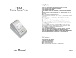
DL300 FINGERPRINT LOCK
USER MANUAL
Please read this manual carefully before operation.
Please keep this manual for later reference.
Intelligent Biometric Controls, LLC.
Tel: (513) 336-9292 Fax: (513) 336-0626
Http://www.fingerprintdoorlocks.com
E-mail: [email protected]
All rights reserved. Reproduction without permission is prohibited.
Table of Contents
1. Introduction…………………………………………………………………………………………………01
1.1
1.2
1.3
1.4
Features………………………………………………………………………………………………………01
Structure & accessories………………………………………………………………………………01
Checklist…………………………………………………………………………………………………………03
Parameters …………………………………………………………………………………………………03
2. Getting Started………………………………………………………………………………………………04
2.1 Lock Installation……………………………………………………………………………………………04
2.2 Fingertip Position for Fingerprint Template Enrollment ………………………04
2.3 Glossary…………………………………………………………………………………………………………05
3. Operation……………………………………………………………………………………………………05
3.1 Operation Flowchart for a mechanical key………………………………………………………05
3.2 Unlocking with mechanical key……………………………………………………………………… 05
3.3 Locking with mechanical key …………………………………………………………………………05
3.4 Dead Locking…………………………………………………………………………………………………05
3.5 Fingerprint template enrollment………………………………………………………………………05
3.5.1 Ordinary fingerprint key……………………………………………………………………………06
3.5.2 Master fingerprint key………………………………………………………………………………06
3.6 Unlocking with an enrolled fingerprint……………………………………………………………06
3.7 How to set to Normal Open Status …………………………………………………………………07
3.8 How to cancel Normal Open Status………………………………………………………………07
3.9 How to delete enrolled fingerprint……………………………………………………………………07
4. Maintenance Guide………………………………………………………………………………………07
4.1 Daily Maintenance…………………………………………………………………………………07
4.2 Caution……………………………………………………………………………………………………08
4.3 Troubleshooting ……………………………………………………………………………………08
Appendix
…………………………………………………………………………………………………………09
A. Lock Installation Guide…………………………………………………………………………………………09
B. Left Handing & Right Handing……………………………………………………………………………13
1. Introduction
1.1 Features
- Adopts optical fingerprint sensor, fingerprints can’t be duplicated.
- Fingerprint can be enrolled and erased directly on the lock, no computer needed.
- Two options to unlock the door: fingerprint or mechanical key.
- 180 users maximum
- Normal open status can be set and deleted.
- Two colors options (where “XX” is either “LH” or “RH”):
A. DL300-XXB : Polished brass with PVD coated;
B. DL300-XXC : Satin chrome
- Standalone version, easy to install.
1.2 Structure & accessories
Lock Structure
1
Accessories
Mechanical keys
3mm Hexagonal Screwdriver
Mechanical Key
2mm Hexagonal Screwdriver
Tapping screw
Strike Plate
Fixing screw
Strike
2
1.3 Checklist
Item
Description
Qty
1
Front body
1pc
2
Back body
1pc
3
Mortise
1pc
4
Handle
2pcs
5
Cylinder
1pc
6
Mechanical key
2pcs
7
Cylinder cover
1pc
8
Hexagonal screwdriver
2pcs
9
Strike
1pc
10
Strike plate
1pc
11
Side plate
1pc
12
Small Fittings
1set
13
Battery
4pcs
14
User guide
1set
15
Quality Certificate
1pc
3
1.4
Parameters
Operating Environment
Operating Temperature
Between -8ºC and +85ºC
Storing Temperature
Between -25ºC and +85ºC
Humidity
Between 20%RH and 90%RH
Technical Parameters
Parameter
Description
Resolution of sensor
Optical sensor
500 dpi
Antistrike ability of sensor
surface
Remain good condition after being jabbed with a 4H pencil at
a 20cm’s distance
Authentication speed
The motor working time after unlocking with valid fingerprint.
Authentication methods
1:N or 1:1
FRR
≤ 1%
FAR
≤ 0.0001%
Angle for putting finger
Fingerprint scanning
+/- 45o
Twice to get one fingerprint template
Fingerprint
saved
All enrolled fingerprint template will be saved while replacing
new batteries
Fingerprint sensor
template
Value
<1S
Operating Voltage
4 AA alkaline batteries
4.5 V~6.0 V
Battery Life
The time 4 new batteries run down
12 months
Static current
When the lock is in static status.
<10µA
Dynamic current
The working current during unlocking process
110~180mA
User capacity
The maximum No. of fingerprints could be enrolled into the
lock.
180pcs
4
2. Get started
2.1 Lock Installation
Refer to Appendix A for detailed lock installation steps.
- Power supply on and Initialization
Step 1 Put 4 AA alkaline batteries into the battery box;
Step 2 The red and green indicators flash once at the same time;
Step 3 The motor makes a “zi” sound;
Step 4 The buzzer makes a long beep.
Step 5 The lock has been initialized successfully.
2.2 Fingertip Position for Fingerprint Template Enrollment
Put a fingertip on the sensor, this fingerprint lock allows the deviation angle to the side not
exceeding +/-450.
√correct
X wrong
Thumb, forefinger and middle finger are recommended for fingerprint template enrollment.
Note the followings while enrolling.
1. Place the fingertip center right on the sensor.
2. Press flat and evenly the capture window with a fingertip, and cover the sensor surface
as wide as possible.
3. Place a fingertip at nearest the same position of the sensor each time after the
fingerprint template is collected.
4. Slightly press the sensor if a fingertip is wet and dry it if necessary.
5. Press the sensor with a bit bigger strength if the fingertip is too dry.
Note: Select a fingertip with perfect finger mark to enroll its fingerprint template.
5
2.3
Glossary
Normal open status: The lock keeps open no matter the door is closed or not. The lock
can be opened by rotating outside handle any time without neither mechanical key nor
fingerprints.
Locking Status: The door will be locked up when it is closed and a key is needed to open
the door.
Dead Locked Status: The dead bolt is extended when the door is locked up.
3. Operation
3.1 Operation Flowchart for a Mechanical Key:
Power supply on - Lock Initialization
- Locking/unlocking with a Mechanical Key
- Fingerprint Key Enrollment
-
Locking/unlocking
3.2 Unlocking with mechanical key
Step 1: Plug the 2mm hexagonal screwdriver into the small hole at the bottom of the front
body of the lock to loosen the screw inside – turn the screwdriver slightly to avoid the
screw from dropping, till the cylinder can be taken off.
Step 2: Insert a mechanical key in the cylinder and turn it down 180 o clockwise for right
handing doors or anticlockwise for left handing doors, the buzzer will make a long beep and
the door is unlocked.
3.3 Locking with mechanical key
After the door being unlocked with a mechanical key, turn back the mechanical key up 180o
anticlockwise for right handing doors or clockwise for left handing doors and pull it out.
Cover the cylinder with the cylinder cover. The Door has been automatically locked up.
3.4 Dead Locking
To dead lock the door inside: turn the dead bolt knob to extend the rectangular dead bolt.
6
3.5 Fingerprint Template Enrollment
3.5.1 Ordinary fingerprint key : means fingerprints which can only unlock while the
deadbolt doesn’t extend (The door is locked with latches only, but the deadbolt doesn’t
extend).
Step 1. Use the 2mm hexagonal screwdriver to take off the cylinder cover. (After the
operation with a mechanical key, cover the cylinder back in the correct direction
and press it with strength).
Step 2. DO NOT extend the deadbolt.
Step 3. Insert a mechanical key into the cylinder and turn it 180 o clockwise, the buzzer
makes a long beep and the lock has been unlocked and entered into fingerprint
template enrollment status.
Step 4. Put a fingertip onto the sensor, rotate outside handle with another hand, the red
indicator flashes, which is the first enrollment. Move your finger away after a long
beep is heard.
Step 5. Put the same fingertip onto the sensor IMMEDIATELY for second enrollment,
move the finger away after 2 long beeps are heard. The 2 long beeps indicate that
the fingerprint template enrollment has succeeded.
Note: If 2 short beeps were heard, this indicates the failure of enrollment. Please
try again.
Step 6. Repeat Step1 to Step 5 to enroll more fingerprints.
Step 7. Turn the mechanical key back to original position to finish the fingerprint
enrollment status, and the lock is in locking status.
3.5.2 Master fingerprint key : means fingerprints which can even unlock while the
deadbolt extends (The door is locked with both latches and deadbolt ).
Step 1. Use the 2mm hexagonal screwdriver to take off the cylinder cover. (After the
operation with a mechanical key, cover the cylinder back in the correct direction
and press it with strength).
Step 2. Insert a mechanical key into the cylinder and turn it 180 o clockwise, the buzzer
makes a long beep and the lock has been unlocked and entered into fingerprint
template enrollment status.
Step 3. Put a fingertip onto the sensor, rotate outside handle with another hand, the red
indicator flashes, which starts the first enrollment.
Step 4. IMMEDIATELY extend the deadbolt with another hand, make sure the deadbolt
was extended before you hear a long beep. Move your finger away after a long
beep is heard.
Step 5. Put the same fingertip onto the sensor IMMEDIATELY for second enrollment,
move the finger away after 2 long beeps are heard. The 2 long beeps indicate that
the fingerprint template enrollment has succeeded.
Note: If 2 short beeps were heard, this indicates the failure of enrollment. Please
try again.
Step 6. Repeat Step1 to Step 5 to enroll more fingerprints.
Step 7. Turn the mechanical key back to original position to finish the fingerprint
enrollment status, and the lock is in locking status.
7
3.6 Unlocking with an enrolled fingerprint
Make sure the door is in locking status before you unlock it.
Step 1. Put an enrolled fingertip onto the sensor and rotate the handle. The green indicator
should lights up and red indicator should flash.
Step 2. The motor in the lock makes a “zi” sound and the buzzer makes a long beep.
Step 3. Rotate the handle to open the door.
Note:
1. The door will be locked automatically if its handle hasn’t been rotated within five seconds
after the long beep.
2. If the lock denies a valid fingerprint along with the flashes of the red indicator and two
short beeps of “di”, it indicates that fingertip’s position is incorrect. Adjust its position and
try again.
3.The response of the lock will be the same as in No 2 if an invalid fingerprint is used to
unlock the door.
3.7 How to set to Normal Open Status
Note: Normal Open Status can only be set with enrolled fingerprint.
(1) During locking status, put an enrolled fingerprint on the sensor, rotate outdoor
handle, the green and red indicators flash, 3 seconds later, the motor drives, move away the
finger from the sensor, rotate the handle and the lock will come into unlocking status;
(2) Immediately put the finger onto the sensor, rotate the handle twice, a long beep will be
heard. The lock has been set to Normal Open Status.
3.8 How to cancel Normal Open Status
When a lock is in Normal Open Status, rotate the deadbolt knob to extend the deadbolt
latch, the motor makes a “zi” sound and the door is locked.
The Normal Open status has been cancelled.
3.9 How to delete enrolled fingerprints?
Step 1. Insert a mechanical key in the cylinder and turn it clockwise to unlock the door,
Step 2. After a long beep is heard, stop power supply by taking out 1 of the batteries.
Step 3 Ten seconds later, replace the battery being took out.
Step 4. The red and green indicators flash once at the same time. The motor makes a “zi”
sound and the buzzer makes a long beep.
Step 5. Loose the handle and turn the mechanical key back to the original position to lock
the door.
CAUTION: All fingerprint templates stored in the lock will be deleted. Please make
sure you want to do so.
8
4 Maintenance Guide
4.1 Daily Maintenance
Sensor & Lock Surface Clean
Daily Maintenance
Keep sensor & lock surface clean
and dry. Clean it with soft and dry
cloth if any stain on the lock surface.
Check fixing screws, handles, side
plates and strike plates every two
months. Fasten any loosen screws.
4.2 Caution
Do not open the door with a wet finger.
Do not touch the surface with corrosive materials.
Do not hang anything on the handle.
Adjust the position of the strike plate immediately if the latches can not extended into it
due to the door frame distortion.
The maximum number of enrolled fingerprints is 180 pcs. You need to clear the lock when the
memory is full.
When the batteries are running down, the red indicator flashed to alert low voltage. Although
you can still unlock the door 20-30 times, you should replace new batteries ASAP.
Keep the mechanical keys carefully to prevent from being burglarized.
4.3 Trouble Shooting
Problem
When putting a fingertip on the capture
window, the red indicator light up and the
buzzer makes two short beeps, but the
door cannot be opened.
When putting a fingertip with a valid
fingerprint “key” on the sensor, the red
indicator flashes and the buzzer makes
two short beeps, but the door cannot be
opened.
During the collection operation, the
green indicator flashes after the finger
moves away, and the red indicator
makes a flash and then goes out.
During the collection operation, a
fingerprint template has been collected
successfully more than once, and then
the red indicator flashes and the buzzer
make two short beeps.
Possible Reasons
1. Invalid fingerprint “key;
Solutions
Use a valid fingerprint
Key.
2. Deleted fingerprint “key”.
The fingertip is wet.
Dry the fingertip with soft
and dry cloth and try
again
Incorrect fingertip position is Adjust the fingertip
used.
position and try again.
The enrollment fails as no Repeat the enrollment
common fingerprint template operation.
part can form from the
several collections.
9
Appendix:
A: Lock Installation Guide
1. Door Requirement
1.1 Wooden door with thickness from 38mm to 55mm.
1.2 If the door surface is decorated, the distance from the decorative edge to the doorframe
must be between 108mm and 150mm.
1.3 If the lock is to be installed on a hollow door, underlay with a piece of wooden board the
part of the door where the lock body is to be fixed on.
1.4 Thickness of door frame must be >30mm.
1.5 Locate the centerline of handle of the lock according to user’s request; the
recommended height for it is one meter above the ground.
2. Installation Tools
Auger: Auger bit: ф12mm to ф13mm, ф22mm; Power Drill;
Drill bit: ф35mm to ф40mm; Power saw; Power saw blade
Chisel; Hammer; Screwdriver; Thread board; Template; Pencil
3. Installation Steps:
Step 1. Draw the centerline of handle according to user’s request,
Draw installation lines according to the template (Refer to Diagram 1);
Step 2. With ф22mm auger bit to drill the six holes according to the drawn lines on the door
side (Refer to Diagram 1). The holes’ depth should be 11-12cm. (Refer to
Diagram 2). With a chisel excavate the six holes to make a rectangle slot, and
check and adjust it to fit the size of the mortise (Refer to Diagram 3).
Step 3. Withф12mm-13mm auger bit drill the four holes for fixing screws and one deadbolt
knob hole on the exterior and interior faces of the door according to the drawn lines.
(Refer to Diagram 4)
Step 4. According to the template, with a power saw cut a square hole, with a ф
35mm-40mm drill bit drill a cylinder hole and a handle hole.
Step 5. Install the mortise and fix it with a tapping screw. Install side plate and fix it with
screws. (Refer to Diagram 5)
Step 6 Install the lock cylinder: insert a mechanical key halfway in the cylinder and turn it to
screw the cylinder slightly till a position that the cylinder lid keeps even with the
lock surface when it has been put on, adjust the cylinder with the mechanical key
to make the key slot in horizontal position, and fix it with a screw at the side of the
door. (Refer to Diagram 5)
10
Diagram 1
11
Diagram 2
Diagram 3
Diagram 4
Diagram 5
Step 7. After the cylinder has been installed, insert the end with gutters on edges of the long
square shaft into the square hole on the door to locate the outside handle.
Step 8. Insert the fixing shaft in the hole of the handle slightly to install the front body. Make
the wire socket on the front body through the square hole.
Step 9. Install the back body : connect the back body to the mortise by screws , put in 4 AA
12
alkaline batteries. (Refer to Diagram 6).
Diagram 6
Step 11. Tighten the armature plate by two screws;
Step 12. Test the lock as per operation instruction.
4. Strike Installation
Step 1. Make the five latches of the lock extended until that they touch the side of the door
frame and draw lines on the frame according to the position of latches to decide the
upper and lower lines of the strike.
Step 2. Measure the width of the latches to decide the left and right lines for the strike to be
installed on the frame.
Step 3. Cut a hole with chisel on the frame and install the strike.
Step 4. Fix the strike with screws. (Refer to diagram 7)
13
Diagram 7
B: Left Handing & Right Handing
Stand outside and face the door, if the hinge is on the left, then the lock is a Left Handing
one; if the hinge is on the right, and then the lock is a Right Handing one. To be shown as
follows.
Left handing
Right handing
----------------------- End --------------------
Copyright C 2004 Shenzhen Ideal Microelectronics Co., Ltd. All rights Reserved.
14