1
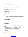
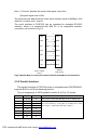
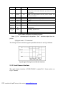
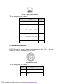
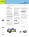
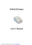
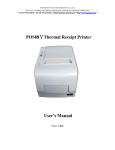
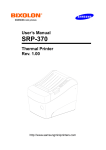
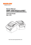
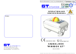
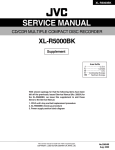
®
SPRT
SP-POS76Ⅲ Receipt Printer
User’s Manual
(Ver 1.00)
Beijing Spirit Technology Development Co.,Ltd
PDF created with pdfFactory trial version www.pdffactory.com
Content
Content.............................................................................................................................................. 2
Notes For Use ................................................................................................................................... 3
Chapter 1 Feature and Performance.......................................................................................... 3
1.1 Print Paper........................................................................................................................... 3
1.2 Ribbon................................................................................................................................. 4
1.3 Print Font and Command .................................................................................................... 4
1.3.1 Print Font .............................................................................................................. 4
1.3.2 Print Command..................................................................................................... 4
1.4 Interface .............................................................................................................................. 4
1.5 Power Supply...................................................................................................................... 5
1.6 Working Environment......................................................................................................... 5
1.7 Outline Dimension .............................................................................................................. 5
1.8 Model classification ............................................................................................................ 5
Chapter 2 Operation Specification............................................................................................ 6
2.1 Printer Appearance.............................................................................................................. 6
2.2 Ribbon and Paper Installation ............................................................................................. 7
2.2.1 Ribbon Installation................................................................................................ 7
2.2.2 Paper Installation.................................................................................................. 7
2.3 Interface .............................................................................................................................. 8
2.3.1 Serial Interface...................................................................................................... 8
2.3.2 Parallel Interface................................................................................................... 9
2.3.3 Cash Drawer Interface....................................................................................... 10
2.3.4 Power Connection.............................................................................................. 11
2.4 Indicators and Buttons ...................................................................................................... 12
2.5 Memory DIP Switch ......................................................................................................... 12
2.6 Self-test ............................................................................................................................. 13
2.7 Hexadecimal Printing........................................................................................................ 14
PDF created with pdfFactory trial version www.pdffactory.com
Notes For Use
● Don't plug or unplug the interface cable,printer head cabe or power cable under the
state of power on,or else it will cause the damage of printer or control board.
● At any time,don’t take the wastepaper or other attached objects by hard things(such as
tweezers,blades and so on),in order to avoide the permanent damage to the printer head.
● After printing,if open the cover,don’t touch the printer head or motor case by hands, in
order to avoid scald caused by the high temperature of the metal.
Warning
This is A level products.In living condition,the products may cause radio
jamming.In this case,may need user to take practicable measures to the
jamming.
Chapter 1 Feature and Performance
1.0 Print Performance
●Print method:9 pin inpact dot matrix
●Print paper width:76±0.5mm or 57.5±0.5mm
●Print density:40cpl-200(all point)/400(half point)
●Print speed:4.4lines/s;57mm paper width:5.6lines/s
●Feeding speed:80mm/s
●Reliability:
(1)MCBF:7,500,000lines
(2)TPH:15,000,000characters
●Valid print width:40cpl-40(7×9)/35(9×9)
1.1 Print Paper
● High quality commone white paper or impact paper roll
● Paper width ---------- 76±0.5mm or 57.5±0.5mm
Outside diameter ---------- ф80mm
Inside diameter---------- ф13mm
Simplex paper thickness ---------- 0.06mm~0.085mm
Impact paper thickness(1 original+2 copies):0.05mm~0.20mm
PDF created with pdfFactory trial version www.pdffactory.com
● Paper loading:Drop-in easy loading
● Cutting method:POS76Ⅲ-D series:manually tear off;
POS76Ⅲ-B series:partial cut
1.2 Ribbon
ERC-39 purple or black(or two-color ribbon NH37702)
1.3 Print Font and Command
1.3.1 Print Font
● ANK character set,7×9dots or 9×9dots
● GB18030,16×16dots
Font description:
7×9dots(W×H):half point printing,ten half points on the horizontal
direction;
9×9dots(W×H):half point printing,twelve half points on the horizontal
direction;
Size of a point is:0.318mm(W)×0.353mm(H)。
1.3.2 Print Command
Compatible with the ESC/POS command set of EPSON,please see the
details in developer guide.
1.4 Interface
●RS-232C Serial Interface:
DB-25 socket(male),support DTR/DSR and XON/XOFF handshaking
protocol.
Baud rate:1200,2400,4800,9600,19200bps adjustable.
Data structure:1 start bit + (7 or 8)data bits + 1 stop bit
Parity checking:no parity or odd,even parity is optional.
●Parallel interface:
36 pin,8-bit parallel interface,support BUSY/ACK hadshaking protocol,
TTL signal level
●Ethernet interface:
Standard ethernet interface.
●USB interface:
PDF created with pdfFactory trial version www.pdffactory.com
USB interface
●Cash drawer control
DC24V,1A,6pin RJ-11 socket
1.5 Power Supply
●DC24V±10%,2A,A-1009-3P power socket
1.6 Working Environment
●Operation temperature:0℃~50℃
Relative humidity:10%~90%
●Storage temperature:-20℃~60℃
Relative humidity:10%~90%
1.7 Outline Dimension
●259 mm(L)×160 mm(W)×150 mm(H)
1.8 Model classification
Model
Cutter
Interface
SP-POS76Ⅲ-BS
With
RS-232C serial interface
SP-POS76Ⅲ-BP
With
Parallel interface
SP-POS76Ⅲ-BE
With
Ethernet interface
SP-POS76Ⅲ-BU
With
USB interface
SP-POS76Ⅲ-DS
Without
RS-232C serial interface
SP-POS76Ⅲ-DP
Without
Parallel interface
SP-POS76Ⅲ-DE
Without
Ethernet interface
SP-POS76Ⅲ-DU
Without
USB interface
PDF created with pdfFactory trial version www.pdffactory.com
Chapter 2 Operation Specification
2.1 Printer Appearance
Upper cover
Paper-out slot
Open button
Paper-end indicator(red
Feed button(FEED
Status indicator(red)
Power
Power indicator(red)
Cash drawer interface
Interface socket
Fig.2-1 printer appearance
PDF created with pdfFactory trial version www.pdffactory.com
Power socket
2.2 Ribbon and Paper Installation
2.2.1 Ribbon Installation
Steps of ribbon installation are as below
(1)Shown as in figure 1,open front cover
(2)Shown as in figure 2,put the ribbon into printer head,turn the knob as the
direction shown on it for two~three circles,just like shown in figure 3.
(3)Close the front cover
Fig 1
Fig 2
Fig 3
2.2.2 Paper Installation
The installation steps of paper are as below:
Press the button on the right side,open the paper cover,and put paper into the
paper holder(the direction is as shown in fig2-2). Draw a certain length of the
paper roll, put the paper end on the print head, close the upper cover and
press it downwards lightly.
PDF created with pdfFactory trial version www.pdffactory.com
Fig2-2 Paper Installation Sketch
2.3 Interface
2.3.1 Serial Interface
The serial interface of POS76Ⅲ printer is compatible with RS-232C,use
DB-25(female)socket, DTR/DSR handshaking protocols.The pin order of the
serial port is as Fig.2-2 shows:
Fig.2-2 Pin Order of Serial Port
The pin assignment of serial interface is shown in Fig. 2-3:
Pin No.
Signal
Name
Direction
Source
Description
1
FG
——
——
Ground
2
TXD
Output
Printer
Printer transmits control
X-ON/X-OFF and data to host
3
RXD
Output
Host
Printer receives data from host
4
RTS
Output
Printer
The same with 20pins DTR signal
6
DSR
Input
Host
Signal “MARK” means the host is busy
and can not receive data.Signal
“SPACE” means the host is ready to
receive data.
7
GND
——
——
Signal Ground
20
DTR
Output
Printer
Signal “MARK” means the host is busy
and can not receive data.Signal
“SPACE” means the host is ready to
receive data.
Fig. 2-3 The pin assignment of serial interface
PDF created with pdfFactory trial version www.pdffactory.com
code
Note: (1)“Source” denotes the source that signal come from;
(2)Logical signal level is EIA.
The baud rate and data structure under serial interface mode is 9600bps, 8-bit
data bits, no parity and 1 stop bit.
The serial interface of POS76Ⅲ can be connected to standard RS-232C
interface. When it is connected with IBM PC or its compatible machine,
connection can accord to Fig.2-4.
3
3
RXD
DTR
RTS
TXD
DSR
TXD
20
6
4
8
DSR
CTS
2
2
6
4
7
5
5
7
RXD
DTR
GND
GND
CTS
Printer 25PIN
Socket
RTS
IBM PC
DB9 Socket
Fig.2-4 Sketch Map of Connection between POS76III and IBM PC Serial Interface
2.3.2 Parallel Interface
The parallel interface of POS76III printer is compatible with CENTRONICS,
supports BUSY or ACK handshaking protocol.
The pin assignment of 36PIN parallel interface is as Fig. 2-5 shows:
Pin No.
Signal
Direction
Description
1
STROBE
In
Strobe pulse to latch data, Reading occurs at falling edge.
2
D1
In
3
D2
In
4
D3
In
These signals represent the 1st bit to 8th bit of the parallel
data representatively, each signal is at HIGH level when
data is logic 1, and LOW when data is logic 0.
5
D4
In
6
D5
In
7
D6
In
8
D7
In
PDF created with pdfFactory trial version www.pdffactory.com
9
D8
In
10
ACK
Out
Answer pulse, LOW level signal indicates that data have
already been received and the printer gets ready to receive
the next data.
11
BUSY
Out
HIGH level signal indicates that the printer is BUSY and
can not receive data.
12
PE
Out
HIGH level signal indicates that paper is end.
13
SEL
Out
Pulling up to HIGH level signal by a resistor
17
FG
---
CGND
18
Logic-H
---
Logic “1” level
32
nFault
Out
Low level means the printer is at fault
NC
---
No connection
16,19~30,
33
GND
---
Grounding, logical 0 level
35
+5V
---
+5V power
14,15,17
18,34,36
Fig.2-5 36Pin assignment of parallel interface
Note: (1)“In” denotes input to the printer,
“Out” denotes output from the
printer.
(2)Signal level is TTL standard.
The timing chart for interface signal of parallel interface is as Fig.2-6shows:
Fig.2-6 Signal Timing Chart of Parallel Interface
2.3.3 Cash Drawer Interface
The cash drawer interface of POS-POS88Ⅴ adopts RJ-11 6-pin socket, as
Fig.2-7 shows:
PDF created with pdfFactory trial version www.pdffactory.com
Fig.2-7 Cash Drawer Interface
The pin assignment is as below:
Pin No.
Signal
Direction
1
Chassis Ground
——
2
Cash drawer
signal 1
driver
Out
3
Cash drawer
status signal
on/off
In
4
+24VDC
——
5
Cash drawer driver signal
2
Out
6
Signal ground
——
2.3.4 Power Connection
POS76Ⅲ uses the external power supply adopter as 24V±10%、2A,power
socket is A-1009-3P model,as Fig. 2-8 shows:
Fig.2-8 Power Socket
The pin assignment is as below:
Pin No.
Signal
1
+24VDC
2
Ground
PDF created with pdfFactory trial version www.pdffactory.com
3
NC
Recommend to use the power supply which is offered by factory,user can
put it into the printer outlet directly.If use other power supply,it must
meet requirement of rating voltage and power,and make sure it is properly
connected,if not,it will can not ensure the printer on normal work,may even
damage the printer.
2.4 Indicators and Buttons
There is one button and three indicators on POS76III printer.【FEED】is paper
feeding button, the function of its enabling or disabling the button on/off can be
set by print command, when the button is enabled, press 【FEED】 button,
then the paper presenting driver starts up and paper feed into the printer;
release【FEED】 button, paper feeding stops. The green POWER light is the
power indicator, red ERROR light is status indicator, it is dark when the printer
works normally, while it flashes when reporting an abnormal emergency.The
red PAPER OUT light is the paper ending indicator,when there is no paper in
printer head,the light will be on, it is out under normal condition.As the
following form shows:
Error
Indicator and Buzzer Status
Description
Paper ending
“ERROR” indicator flashes
Paper is running out
No paper
“PAPER OUT” indicator is on
Paper has run out
Up
“ERROR” indicator flashes
Close the cover tight it
will return to normal.
Print head
overheat
“ERROR” indicator flashes and
buzzer rings
2.5 Memory DIP Switch
Function of Msw2 and Msw8 is as below:
PDF created with pdfFactory trial version www.pdffactory.com
It
will
recover
automatically when the
print head cools.
Memory DIP Switch Msw2
DIP
48 (Off)
Function
49(On)
Default Value
1
No definition
Off
2
No definition
Off
3
Select Chinese Font System
4
No definition
Off
5
No definition
Off
6
No definition
Off
7
No definition
Off
8
No definition
Off
GB18030
GB2312
Off
Memory DIP Switch Msw8
DIP
Function
48 (Off)
49(On)
Default Value
1
No definition
Off
2
No definition
Off
3
No definition
Off
4
No definition
Off
5
Select Open Mode of
Paper Holder Cover
Paper Out
6
No definition
Fixed As Off
7
Send busy state signal
when receiving buffer
Remain 256
bytes
Remain 138
bytes
Off
8
Cover open during printing
Error recover
automatically
Use
command to
recover
Off
Cover Open
Off
Off
Msw8-5:If select “off”,printer will send paper out state when the cover open or close;
If select “on”,printer will send cover open state when the cover open or close.
2.6 Self-test
Method of self-test:press【FEED】 button and turn on the printer,loose the
button when hear the sound of peep(if there is a cutter,it will be the sound of
cutter turning),then the printer will print out the content of self-test below:
Version No. of the printer,type of interface and disposition,size of the
buffer,number of remain bytes,type of handshaking,type of cutter,type of word
stock,paper width,CPL,set of memory DIP switch,and so on.
After printing the state of printer,it will print the information below:
If you want to continue
SELF-TEST printing
PDF created with pdfFactory trial version www.pdffactory.com
please press FEED button
At this moment,the red “PAPER OUT”indicator will flash,this means the
printer enter the state of self-test printing,press 【FEED】 can begin to self-test
print.
2.7 Hexadecimal Printing
Turn on the printer according to the steps below,it will enter the mode of
Hexadecimal Printing.
Open the cover;
Press【FEED】button,and switch on;
Close【FEED】button,the printer will print out 3 lines as below:
Hexadecimal Dump
To terminate hexadecimal dump,
Press FEED button three times.
This means the printer has entered hexadecimal printing mode,and under
this mode,all of the input will be printed out as hexadecimal number,feed one
line with single-click of “FEED” button,after 3 times,it will print out
“Hexadecimal Dump Completed” and exit hexadecimal printing mode.
PDF created with pdfFactory trial version www.pdffactory.com