1
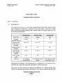
Roadway Signage Upgrades at Bush IAH
HNTB Corporation
Houston, Texas
PN552/CIP No : A-028 5
SECTION 1042 5
SIGNS
PART 1 - GENERA L
1 .01
1 .02
1 .03
SECTION INCLUDE S
A.
Sign panel and supports .
B.
Demountable copy .
QUALITY ASSURANCE
A.
All work under this Item to be performed by manufacturer having a minimum of 5
years experience in fabricating and installing signs of the sixes and types specifie d
for this project .
B.
Design and fabrication Criteria : AASHTO Standard Specifications for Structura l
Supports for Highway Signs, Luminaries, and Traffic Signals and Interi m
Specifications thereto .
SUBMITTAL S
A.
Follow Section 01340 - Shop Drawings, Product Data and Samples .
B.
Submit Shop Drawings including :
1.
Provide shop drawings for fabrication and erection of signs . Include plans ,
elevations, and large-scale sections of typical members and othe r
components . Show anchors, grounds, reinforcement, accessories, layout ,
and installation details .
2.
Signboards and Copy : Provide message list for each sign required ,
including large-scale details of wording, layout, and font of lettering .
Furnish full-size spacing templates for individually mounted dimensiona l
letters and numbers.
3.
Location of each sign during each stage of construction . Includin g
temporary signs T108 and T210 . Sign T108 text shall include Avis, Hertz ,
and National rental car badges and mounted on the right shoulder . Sign
T210 text shall include Advantage, Avis, Hertz, and National rental ca r
badges. The badges from the existing sign being removed can be used along
with the corresponding arrows .
SIGN S
10425- 1
3-8-99
HNTB Corporation
Houston, Texas
Roadway Signage Upgrades at Bush IA H
PN552/CIP No : A-028 5
4.
C.
Samples for verification of color, pattern, and texture selected, and complianc e
with requirements indicated :
1.
1 .04
Provide detailed design for concrete foundations for new and/or relocate d
signs .
Submit to Designer for approval the following samples :
a . Four 12-inch square samples of each sign face (Terminal icons an d
black) material with proposed color of background coating applied .
Where finishes involve normal color and texture variations includ e
sample sets showing the full range of variations expected .
PROJECT CONDITIONS
A . Field Measurements : Take field measurements prior to preparation of sho p
drawings and fabrication to ensure proper fitting . Show recorded measurement s
on final shop drawings . Coordinate fabrication schedule with constructio n
progress to avoid delay.
PART 2 - PRODUCT S
2.01
MATERIALS
A.
Acceptable aluminum alloys for this Item are given in AASHTO Standar d
Specifications for Structural Supports for Highway Signs, Luminaries, and Traffi c
Signals.
B.
Sign Panels : Use existing panels . Existing borders do not
1.
C.
Sign panel connections to be as shown on Plans and as approved b y
Designer.
Copy:
1.
Each letter and symbol shall be applied to a badge supplied with mountin g
holes and shall be secured to the sign surface with approved rivets . The use
of tape, glue or other substances to secure to the sign face during fabricatio n
or in its final form, other than approved rivets, will not be allowed .
2.
Panels shall be attached flush against sign faces after background materia l
has been applied.
3.
Spacing of all legends and borders shall be as specified with an allowabl e
SIGNS
10425-2
3-8-99
Roadway Signage Upgrades at Bush IA H
HNTB Corporation
Houston, Texas
PN552/CIP No : A-028 5
tolerance of plus or minus 2 percent on any individual measurement a s
shown on the approved shop drawings. A sufficient number of rivets shal l
be used to securely fasten demountable legends and borders to sign panels .
PART 3 - EXECUTION
3.01
3.02
CONSTRUCTION METHOD S
A.
Paint all bolt heads, rivets and hardware showing on sign face the same color as
adjacent background material .
B.
Prior to placing new badges, wash the sign panel with cleaning solutio n
recommended by sign panel coating manufacturer to remove all grease, oil dirt,
smears, streaks, finger marks, and other foreign particle s
C.
The Contractor shall make all necessary arrangements to obtain from the Cit y
Engineer all clearance and permits necessary to perform his work, and shall b e
totally responsible for maintenance of traffic in accordance with airpor t
regulations. The Contractor shall provide the City Engineer with a detailed wor k
plan and a schedule at least seven days prior to performing the work . The
Contractor shall closely coordinate his work with the City Engineer so as t o
minimize the impact of his work on the operation of the airport .
D.
All work shall be performed in strict conformance with the Contract Documents ,
with OSHA, with all other applicable codes and regulations, and as directed by th e
City Engineer .
INSTALLATION
A. General : Locate sign units and accessories where indicated, using mounting
methods of the type described and in compliance with the manufacturer' s
instructions .
1.
Install signs level, plumb, and at the height indicated, with sign surfaces free
from distortion or other defects in appearance .
2.
The Contractor shall reconnect existing luminaries so as to maintai n
illumination of the relocate signs .
B. Timing : Temporary signs can be used for short durations containing sam e
messages . No temporary sign can be for more than 48 hours .
END OF SECTION
SIGNS
10425-3
3-8-99
Roadway Signage Upgrades at Bush IA H
HNTB Corporation
Houston, Texas
PN552/CIP No : A-028 5
DOCUMENT 1043 8
VARIABLE MESSAGE SIGN S
PART 1 - GENERAL
1 .01 DESCRIPTION
These special provisions are for a full matrix Light Emitting Diode (LED) variable messag e
sign , designed and constructed to withstand a harsh environment . Three types of signs
shall be provided, including Terminal Signs, Entrance Signs, and Parking Signs, each with
the following characteristics :
LED Color
Required
Character Size(s)
Minimum Pixe l
Count (rows x
columns)
Minimum Pixe l
Diameter
Pixel Spacing
(horizontal x
vertical)
LED Viewing
Angle
Mounting
Terminal Sign
Entrance Sign
Parking Sig n
Amber
9" and 12"
Amber
Red
12"
8"
96 x 152
64 x 176
6 x 48
0.9"
0.9"
0.6"
1 .3"x1 .3"
1 .3"x1 .3"
1 .15"x1 .5"
>22°
>22°
>17°
Free Standing
Ground Mount
Free Standing Ground
Mount
Flush Mount on Stati c
Sign Panel Cutout
Throughout the remainder of this specification, if a requirement is not associated with a
particular type of sign, that requirement shall apply to all three sign types.
This section provides technical and functional specifications for variable message sign s
(VMS) to be furnished and installed on this project . The Contractor shall furnish and install
VARIABLE MESSAGE SIGN S
10438- 1
3-8-99
HNTB Corporation
Roadway Signage Upgrades at Bush IA H
Houston, Texas
PN552/CIP No : A-028 5
all materials necessary to provide complete and properly functioning VMSs in accordanc e
with the project plans and these Special Provisions . Miscellaneous equipment, materials ,
and work not mentioned but necessary to provide VMSs that are complete and full y
operational shall be furnished by the Contractor as incidental to the work .
This section describes the minimum VMS requirements . Design of the VMSs shal l
minimize the possibility that failure of any one device or module shall cause total syste m
failure . The failure of one module or subassembly shall not cause the failure of any othe r
module or subassembly .
A VMS system installation shall include, but is not limited to, the following :
1. Variable message signs (include the sign housing plus all electronically controlle d
display elements) .
2. Local VMS controller and firmware .
3. Sign intensity controls .
4. Communication and power cabling between the sign controller and the VMS .
5. Central control computer and software .
6. Technicians laptop computer and software.
1 .02 SUBMITTAL S
A.
Manufacturer Information . The VMS manufacturer proposed to furnish VM S
displays and controllers shall have been in business continuously, for a minimum o f
five years prior to the date of these specifications . Further, the propose d
manufacturer shall have furnished LED VMS systems for a minimum of three (3 )
projects, each with at least five (5) signs and controllers . Each of these signs an d
controllers shall have satisfactorily operated for a minimum of one year. The
Contractor shall submit the names, addresses and phone numbers of individuals wh o
can certify satisfactory operation of signs meeting the above stated requirements .
B.
Shop Drawings . Prior to the purchase or fabrication of the sign, the Contractor shal l
submit four sets of shop drawings of the proposed sign . The shop drawings shal l
show specifically and in detail how the sign meets every requirement of thes e
specifications . One set will be returned to the Contractor with appropriate notation s
within 14 calendar days . This applies to drawings that are resubmitted, as well as t o
drawings submitted for the first time .
VARIABLE MESSAGE SIGN S
10438- 2
3-8-99
Roadway Signage Upgrades at Bush IA H
HNTB Corporation
PN552/CIP No : A-028 5
Houston, Texas
Following review of the submittal data, one set of the shop drawings will b e
returned to the Contractor marked "Review Completed", "Correct as Noted" ,
"Correct and Resubmit", or "Rejected" . The Contractor may proceed with an y
items marked "Review Completed" or "Correct as Noted" . The Contractor shall
not proceed with any items which are marked "Rejected" or "Correct an d
Resubmit" but shall proceed immediately to correct these items and resubmi t
them for review. No time extensions will be granted to the Contractor as a resul t
of the need to resubmit items for review . The Contractor shall not deviate fro m
submittals marked "Review Completed" or "Correct as Noted" without the prio r
written consent of the City Engineer.
Approval by the City Engineer of a shop drawing shall not relieve the Contracto r
of any of his responsibility under the contract for the successful completion of th e
work in conformity with the requirements of the contract documents .
PART 2 - PRODUCT S
2 .01 SIGN MATERIAL S
A. LED's . The display shall consist of LED's that are untinted, non-diffused, high output solid state lamps utilizing aluminum indium gallium phosphide (AlInGaP )
LED technology.
1. Terminal and Entrance Signs shall use LED's that emit a true amber color at a
wavelength of 592 nm (±5 nm) . Parking Signs shall use red LED's with a
wavelength of 600 nm (±5 nm) .
2. Size of all LED's shall be T-1 .75(0.2").
3. LED's shall be nominally rated for 100,000 hours of operation under fiel d
conditions which shall include operating temperatures between -22° F and +185 °
F.
4. Terminal and Entrance Signs shall have LED's with a minimum viewing angl e
of 22°, and Parking Signs shall have a minimum viewing angle of 17° .
5. LED's shall have no less than 50% of the normalized intensity at their maximu m
viewing angle .
6. For each sign, the range of brightness shall be such that the brightest LED use d
is no more than twice as bright as the dimmest LED used .
7. All LED's for a particular sign type shall be identical, and shall all be acquired
from the same manufacturer .
B.
Dimming System . With each VMS display and controller, the Contractor shal l
furnish and install a system which shall sense the ambient light level and provide a
VARIABLE MESSAGE SIGN S
10438- 3
3-8-99
HNTB Corporation
Roadway Signage Upgrades at Bush IAH
Houston, Texas
PN552/CIP No : A-028 5
minimum of sixteen field adjustable dimming levels . Dimming shall be
implemented with high frequency variation of the display duty cycle (pulse widt h
modulation) . The frequency shall be selected to minimize any detrimenta l
flickering.
Terminal and Entrance Signs shall require a dimming system that contains thre e
commercially available photo-electric sensors installed in water-tight meta l
enclosures on the VMS housing . The photo-electric sensors shall have a 0 .25"
(minimum) photosensitive area . The photo-electric sensors shall be capable of
being continually exposed to direct sunlight without impairment of performance .
The water-tight metal enclosure shall have a 1" square (minimum) glass windo w
area . The photoelectric sensors shall be placed so that they sense the ambien t
light levels striking the front and rear of each sign . The sensors shall be locate d
and aimed so that they are not affected by other light sources around the airpor t
such as roadway lighting or headlights . Parking Signs shall require only one
photo-electric sensor on the front of the sign .
C. Pixels . The sign display area shall be formed by a full matrix of individual pixels ,
with a border as shown in the plans . Pixels shall be mounted on replaceable printe d
circuit boards (modules) to form the display, with each module containing no fewe r
than 30 and no more than 120 pixels. Modules shall be removable from the front o f
the sign . Minimum pixel counts for each sign type shall be as defined in Sectio n
1 .01 . The Contractor shall furnish spare modules for each sign type in an amoun t
equal to 10% of the total number of modules used in all the signs, rounded up t o
nearest whole number . Pixels shall meet the following minimum requirements :
1. Minimum pixel diameters and center to center spacing shall be as defined i n
Section 1 .01 .
2. Pixels shall be comprised of several LED's, spaced evenly across the pixel . The
number of LED's in each pixel shall be determined by the manufacturer a s
required to produce 20 Cd of luminous intensity with a 20 mA drive current . A
minimum of four LED's shall be used per pixel .
3. Pixels shall be mounted perpendicular to the display panel, and shall be attache d
with a secure fastening system .
4. Materials used for the pixels shall contain a UV light inhibitor and shall b e
designed for direct exposure to sunlight .
5. Pixels shall be replaceable from the front of the sign enclosure .
6. To minimize the chance of LED's being pushed out of alignment with the sign' s
optical axis, LED's must be mounted no more than 0 .01" from the front side o f
the printed circuit board.
VARIABLE MESSAGE SIGN S
10438- 4
3 -8-99
HNTB Corporation
Roadway Signage Upgrades at Bush IA H
PN552/CIP No : A-028 5
Houston, Texas
7. LED's shall be powered by continuous direct current, not pulses, when they ar e
operating at maximum brightness. When the LED's are operating at less tha n
maximum brightness, the current shall be interrupted as needed to dim the sign .
Multiplexing drive circuits shall not be used .
8. The current provided at maximum brightness must be easily adjustable betwee n
15 mA and 30 mA in 1 mA increments . This adjustment will be altere d
occasionally over the life of the sign to offset the dimming of the LED's as they
age. It is not necessary that maximum brightness be remotely controlled . Upon
installation, the Contractor shall set the maximum brightness current to 20 mA .
D. Display Protection. For Terminal and Entrance Signs, visors or louvers shall b e
installed above each pixel or row of pixels, extending out from the display panel an d
over the pixels as far as needed to provide maximum contrast and legibility withou t
interference to LED display at any viewing angle between 0° and the sign' s
maximum viewing angle . The LED modules should be weather tight and permi t
high pressure washing of the face of the sign. These signs shall not require a
protective window .
Parking Signs shall have a protective clear window that opens to allow access to
the display modules . The window and all associated parts, such as fasteners, shal l
be captive so that they cannot fall to the roadway . The windows shall be dustproof and watertight. If the window is hinged, the hinges shall be at the top of the
window frame.
2.02 FABRICATION, GENERAL
A.
VMSs shall operate from a 120VAC, single phase power source . AC+, AC- and
earth ground shall terminate inside the sign controller cabinet on three (3) separat e
terminal blocks . The AC+ and the AC- bus bars shall be insulated from the chassis .
B.
Terminal and Entrance Signs shall have a 120VAC, 15 Amp convenience GFC I
duplex receptacle mounted in an accessible location inside the sign housing at eac h
end of the sign. The receptacle shall have three (3) wires from the outlet to th e
appropriate terminals.
C.
VMSs shall be entirely self-contained with all electronics internal to the sign . The
bottom of the sign shall be horizontal and all sides shall be vertical .
D.
For Terminal and Entrance Signs, all control circuitry shall be located in a contro l
compartment at one end of the sign housing . All control circuitry shall be located
on printed circuit boards, and all printed circuit boards shall be conformally coate d
to protect against corrosion . This compartment shall have a hinged door utilizing a
stainless steel hinge pin and the door continuously sealed with a neoprene spong e
VARIABLE MESSAGE SIGN S
10438-5
3-8-99
HNTB Corporation
Roadway Signage Upgrades at Bush IAH
Houston, Texas
PN552/CIP No : A-028 5
gasket . The mating surface of the gasket shall be treated with silicone lubricant s o
that it does not stick . The electronics compartment door shall have a door holder t o
hold the door open at the 90 and 120 degree positions .
E.
All printed circuit boards shall be located on a card cage and shall be removabl e
using only simple hand tools . All connections between circuit boards shall be mad e
through plugs or sockets . Harnesses between circuit boards should be cabled in a
neat fashion.
F.
Terminal and Entrance Signs shall have vented thermostatically controlled fans t o
circulate the air inside the VMS housing for cooling . Cooling fans shall turn on
when the internal VMS air temperature reaches 85° F . Fans shall keep the bac k
side of the display modules and the internal housing air temperature below 140° F
when the outdoor temperature is 105° F, the face of the sign is in full sun, and 5 0
% of the pixels are illuminated, drawing 30 mA of current . The ventilation
system shall achieve this performance despite the failure of any single fan . The
fans shall bring in outside air through inlets that have louvers to keep out rain ,
rustproof screens to keep out insects, and replaceable 2" air filters to keep ou t
dust. The filters shall be available from multiple manufacturers and shall b e
located to facilitate replacement .
The fans shall be installed so that they operate in the filtered incoming air strea m
and shall be equipped with a guard that prevents accidental contact with the blade s
of the fans . The fans shall be installed in such a manner as to create a positiv e
pressure within the enclosure relative to its outside environment . The incoming ai r
flow shall be filtered and the exhaust should be vented through the upper portion o f
the electronics and sign housings . The vents shall be rain-tight, shall prevent any
water from dripping into the enclosure, and shall be screened with wire cloth .
The cooling system shall be constructed to allow cleaning of the vents, screens an d
fans. The fans shall be controlled by a thermostat adjustable from 85° F to 120° F .
G.
The sign enclosure shall be constructed of aluminum alloy 5052-H32, at least 0 .125"
thick with all seams continuously welded by the inert gas process . The framing
structural shapes shall be constructed of aluminum alloy 6061-T6 .
H.
The sign housing and interior framing shall be designed to withstand a wind velocit y
of 100 MPH with a 30% gust factor in accordance with AASHTO's Standard
Specifications for Structural Supports for Highway Signs, Luminaires and Traffi c
Signals.
I.
The sign housing shall be constructed to present a clean, neat appearance and th e
sign internal components shall be protected from moisture, dust, dirt and corrosion .
VARIABLE MESSAGE SIGN S
10438-6
3-8-99
HNTB Corporation
Roadway Signage Upgrades at Bush IA H
PN552/CIP No : A-028 5
Houston, Texas
Terminal and Entrance Sign housings shall contain small weep holes for drainin g
moisture that accumulates in the signs from condensation . Weep holes shall b e
designed to prevent the entrance of insects .
J.
Welding . The sign housing welds shall be ground smooth after welding, and the
entire housing shall be cleaned and de-oxidized after welding, and proseal treated i n
accordance with Mil specification C-5541 . The enclosure shall then be primed wit h
zinc chromate and finished inside and out with two(2) coats of high grade enamel .
The front and sides of the housing shall be matte black for proper viewing, and the
top, bottom and back shall be white for cooling .
All exterior seams shall be continuously welded and each weld shall be unifor m
flow. All welds shall be neatly formed and free of cracks, blow holes, and othe r
irregularities .
Welding on aluminum housings shall be done by the gas metal arc (MIG) or the ga s
tungsten arc (TIG) processes using bare aluminum welding electrodes . The
electrodes shall conform to the requirements of the American Welding Society
(AWS) A5.10 for ER5356 aluminum alloy bare welding electrodes .
K.
Terminal and Entrance Signs shall have lifting eyes or the equivalent for movin g
and mounting signs . VMS housings shall be designed such that the VMS can b e
shipped and temporarily stored without damage or undue stresses prior t o
installation . VMSs shall be provided with a temporary storage support frame tha t
will permit the storage of the VMS in an above-ground vertical position withou t
damage to the sign housing.
2 .03 TERMINAL AND ENTRANCE SIGN CONTROLLER
A.
The Contractor shall install a field sign controller in a base mounted cabinet in fron t
of the sign, as shown in the plans . The sign controller for Terminal and Entranc e
Signs shall be microprocessor based and shall be designed to fit in a standard EI A
19" equipment rack. The sign controller shall reject any transmission that does no t
contain its identifying address . The sign controller shall have the capability t o
display any message transmitted from central or any message stored in the sig n
controller memory .
B.
The sign controller shall have permanent memory in the form of plug-in PRO M
integrated circuits, which shall contain the operating firmware and diagnostic tes t
messages . The controller shall also have changeable memory in the form of RA M
integrated circuits with a lithium battery backup that retains the data in memory fo r
a minimum of one year following a power failure . It shall contain the library o f
messages, the message display schedule and changeable operating parameters . The
VARIABLE MESSAGE SIGN S
10438- 7
3-8-99
HNTB Corporation
Roadway Signage Upgrades at Bush IA H
Houston, Texas
PN552/CIP No : A-028 5
memory shall be sufficient to hold at least 32 messages of at least 50 character s
each, and a schedule of at least 100 events .
C.
The sign controller shall contain a local control panel, or shall have controls on th e
front of the controller that provides the following functions :
1. On/Off Switch . This switch shall control the power to the sign controller .
2. Remote/Local Switch . In the remote position, the sign controller receive s
commands from the remote central computer, and in the local position the sig n
controller accepts inputs from the local control panel .
3. Message Select Switches or Keypad . These are used to select stored message s
for display when in the local control position .
D . Each controller shall have at least two EIA-232E communication ports for control .
One of those ports shall be for communication with the central computer and th e
other for communication with a technician's laptop computer connected directly t o
the controller. Each port shall be capable of operation at all standard data rates u p
to 19,200 bits per second . The Contractor shall set the speed to 9600 bits pe r
second. The Contractor shall connect the port for the central computer to the fibe r
optic transceiver, also installed by the Contractor in the controller cabinet. The
transceiver is described elsewhere .
In addition, the controller shall have one or more communication interfaces with th e
equipment in the sign, for such things as sign control and brightness adjustment .
E. The sign shall contain a time-of-year clock with a lithium battery backup . The
battery shall keep the clock operating properly for at least 10 years without external
power. The clock shall automatically adjust for daylight savings time and leap yea r
through hardware or software, or a combination of both . It shall be set by the sign
controller's microprocessor. The clock shall be accurate to within 1 second pe r
month, and shall be Year 2000 compliant as described in Section 3 .03 .
F. The sign controller shall monitor the current draw of each LED string to ensure that
the current draw does not exceed 20 mA per pixel . If the current draw exceeds 2 0
mA, the sign controller shall reduce the voltage input to limit the current draw to 2 0
mA or shut down the sign to protect the LED's .
G.
The controller shall contain a "watchdog timer" which shall detect a controlle r
failure and attempt to restart by outputting a reset pulse to the microprocessor .
H.
The sign controller shall have an operating temperature range of—30°F to +165°F .
VARIABLE MESSAGE SIGN S
10438- 8
3-8-99
Roadway Signage Upgrades at Bush IA H
HNTB Corporation
Houston, Texas
PN552/CIP No : A-028 5
2.04 TERMINAL AND ENTRANCE SIGN CONTROLLER SOFTWARE .
A. Display Presentation . The VMS controller shall control the driver modules in such a
way as to create the desired display on the sign . Software shall handle such detail s
as centering text, right justification, left justification, and appropriate spacing o f
letters and words . Software shall also control flash and alternating between pages o f
a two and three-page display.
At the Contractor's option, the National Transportation Communications for IT S
Protocol (NTCIP) may be used . If the Contractor chooses to use this protocol ,
messages shall be communicated and stored using the Markup Language fo r
Transportation Information (MULTI), as defined in the latest edition of the Join t
AASHTO/ITE/NEMA Standards Publication TS 3 .6, National Transportation
Communications for ITS Protocol (NTCIP) Object Definitions for Dynami c
Message Signs (DMS) . The sign's method of operation must be consistent with tha t
standard, if the NTCIP is used .
Software shall be designed to provide a default value for each parameter supported .
The Contractor shall pre-load these default parameters with values that th e
Contractor deems reasonable and as approved by the City Engineer .
B.
Modes of Operation. Signs shall be able to display a static message, a flashin g
message, or a multi page message, as described below .
1. Static Message: The message chosen shall be displayed constantly on the sig n
face until the sign controller is instructed to do otherwise .
2. Flashing Message: A selected portion of the chosen message shall be displayed
and blanked alternately at durations separately controllable in 0 .1-second
increments.
3. Multi Page Messages: The chosen message shall display up to three differen t
pages alternately at durations separately controllable in 0 .1-second increments .
C. Fonts for Terminal Signs . A user shall be able to create and display messages usin g
at least eight fonts, each stored in the controller . Four of the fonts shall be stored i n
the controller by the Contractor. Two of these shall be single stroke characters tha t
are 9" and 12" in height. The other two shall be similar, but bold (double strok e
characters) . The user shall be able to create, download, and store at least fou r
additional fonts in the controller .
D. Fonts for Entrance Signs . A user shall be able to create and display messages usin g
at least four fonts, each stored in the controller . Two of the fonts shall be stored i n
the controller by the Contractor. One of these shall be single stroke characters tha t
is 12" in height. The other one shall be similar, but bold (double stroke characters) .
VARIABLE MESSAGE SIGN S
10438- 9
3-8-99
HNTB Corporation
Roadway Signage Upgrades at Bush IA H
Houston, Texas
PN552/CIP No : A-028 5
The user shall be able to create, download, and store at least two additional fonts i n
the controller.
E.
Response to Errors . In the event of communication errors or controller lock-ups, th e
sign shall retain the current message . In the event of a power failure, the sign shal l
be blanked.
F.
Characters . Signs shall display a message composed of any combination of th e
following characters and shapes in 9" and 12" (Terminal Signs) or 12" (Entranc e
Signs) characters :
1 . A through Z - All upper case letters .
2 . 0 through 9 - All decimal digits .
3. A blank or space .
4. Punctuation marks shown in brackets [ . , ! ? - >_ @ / () ]
5. Special characters shown in brackets [# & * + < >
G.
]
Display Selection : In the absence of instructions to the contrary from the contro l
ports, the controller shall implement a display selected from those stored in it s
memory, based upon date and time as specified in the schedule . It shall use a
schedule stored in random access memory plus its time-of-year clock to select th e
proper display . The schedule system shall permit different schedules for differen t
days of the week plus special schedules for special days, such as holidays .
The display of the scheduled message may be over-ridden by instructions sent fro m
the control ports . A computer shall be able to cause the controller to implement a
particular display selected from the messages stored in its memory, or a new displa y
sent from the central computer . The central computer shall also be able to edit o r
completely replace a message stored in the controller's memory, or revise th e
message schedule . In addition, it shall be able to cause the controller to report it s
schedule or the text of any message stored in its memory .
Software shall incorporate fail-safe procedures to check messages received. If the
message is not received correctly, the software shall not change a message stored i n
memory, the display currently on the sign, the schedule stored in memory, or th e
current time .
Normally, a display shall remain on the sign until either a command to change th e
current display or the schedule in the controller's memory indicates that it is time fo r
a different display. However, it shall be possible to confer a "priority" status upon
the currently displayed message . If a message has priority status, it shall remain on
the sign indefinitely until a new command rescinds the priority . When the controller
VARIABLE MESSAGE SIGN S
10438-1 0
3-8-99
HNTB Corporation
Roadway Signage Upgrades at Bush IA H
Houston, Texas
PN552/CIP No : A-028 5
receives a command to change the sign display while a priority display is on th e
sign, the controller shall transmit a response indicating that the new command wa s
ignored because of the priority status of the current display .
H . Brightness Control. Manual and automatic dimming modes shall be provide d
enabling the user to select the desired mode of operation . The dimming system shal l
select one of sixteen levels from the sensed ambient light . The set points for each o f
the sixteen ambient light levels shall be set within user adjustable software . A use r
shall be able to send a command via the control ports to select a specific brightnes s
level or to direct the controller to select an appropriate brightness based on curren t
lighting conditions .
For each brightness level, a technician shall be able to easily determine wha t
fraction of the full brightness current is applied to the LED's . The technician must
be able to set the current value for a given brightness level to any value between 2 5
% and 100 % of the maximum current in five percent increments, and must be abl e
to easily change these settings via computer commands .
Communication. Controller hardware and software shall permit communicatio n
with the central computer in either polled multidrop or event-driven dial-u p
operation . Initially, the Contractor shall configure all signs for polled multidro p
operation .
In polled multidrop operation, the sign controller shall inform the central compute r
of its current status in response to a query from the central computer . There shall be
constant communication between each sign controller and the central computer .
Several sign controllers may be on the same communication channel, with each
controller assigned a unique ID number . Each controller shall respond only to
messages labeled with its ID or to the broadcast address ID. In the polled multidrop
operation, controllers never initiate communication, but merely transmit thei r
responses to commands or queries from the central computer . The central computer
shall query each controller frequently about its current status in order to detec t
problems.
In event-driven dial-up communication, communication occurs much less often.
Communication is over the public telephone network . Each sign shall have a
unique telephone number, which the central computer dials when it wants to issue a
command or check on the status of the sign. When the controller connects with th e
central computer, it shall transmit a status message that includes an identifying
number for the sign controller . Upon any status changes initiated either remotely o r
locally to the sign controller, the controller shall automatically update the centra l
computer .
VARIABLE MESSAGE SIGN S
10438-1 1
3-8-99
HNTB Corporation
Roadway Signage Upgrades at Bush IAH
Houston, Texas
PN552/CIP No : A-028 5
A.
Bus Architecture . The computer must utilize a PCI bus structure with at least tw o
PCI slots and one ISA slot available after the system has been fully configured t o
perform its functions .
B.
Interfaces. The computer shall be equipped with one parallel and 16 serial ports for
communications with controllers in the field . These ports need not be internal to the
computer .
C.
Hard Disk Drive (HDD) . The computer shall have an internal 8 gigabyte HDD ,
minimum, with an average seek time of 12 ms or less .
D.
CD-ROM Drive. The computer shall have an internal 24X CD ROM drive .
E.
Video Card . The computer shall have a PCI compatible SVGA card with at leas t
four (4) MB of memory. The video card shall be capable of generating a 1024x76 8
non-interlaced image, with 256 colors .
F.
Monitor. The computer shall come with a 17", flat face, digital color monitor . The
monitor shall be compatible with video graphic array (VGA), super VGA (SVGA) ,
IBM XGA, XGA II, IBM 8514/A, 1024x768 non-interlaced, and 1280x1024 non interlaced standards. The monitor shall support the Video Electronic Standard s
Association (VESA) flicker-free modes . Horizontal/vertical size and position, an d
geometric distortion controls shall be easily accessible from the front panel of the
monitor.
G.
Keyboard and Mouse . The Contractor shall provide a standard 104 key Window s
NT compatible keyboard, and compatible two (2) button mouse, each designed to
operate with the provided computer .
2 .07 LAPTOP COMPUTE R
The Contractor shall furnish two laptop computers for maintenance technicians to contro l
and troubleshoot the sign while connected to one of the serial ports of the controller . Each
laptop shall weigh no more than 8 pounds . Each laptop shall be equipped with one interna l
3 .5", 1 .44 Mb floppy disk drive that is removable and interchangeable with the CD-RO M
drive, a removable 24X CD-ROM drive that is interchangeable with the floppy disk drive ,
one parallel and two serial ports, two type II, PCMCIA slots, an attached active matri x
color video display, and internal battery, modem, and a hard disk drive . Each laptop
computer shall come with one spare battery pack and charging unit, and a serial cable t o
connect the laptop to the VMS controller. The laptops shall also have the followin g
features/components .
VARIABLE MESSAGE SIGN S
10438- 14
3-8-99
Roadway Signage Upgrades at Bush IA H
HNTB Corporation
PN552/CIP No : A-028 5
Houston, Texas
A.
Central Processing Unit (CPU) . The laptops shall have an Intel Pentium II CP U
operating at 333 MHz minimum .
B.
Random Access Memory (RAM) . The laptops shall have a minimum of 64 Mb o f
RAM, expandable to 128 Mb .
C.
Hard Disk Drive (HDD). The laptops shall have a 4 gigabyte hard disk drive .
D.
Video Display. The video display shall be capable of generating a 1024x768 non interlaced image, with 256 colors .
E.
Internal Modem. The laptops shall be equipped with an internal 56 Kbps modem.
F.
Backup System. Each laptop shall have an external backup system capable of
making a complete backup of the HDD without operator intervention . The backup
unit shall attach to either the parallel port of the laptop or a provided type II ,
PCMCIA card. The Contractor shall provide backup software which shall allo w
incremental, partial, or full, automatic timed backups at user specified times .
Include reusable media, sufficient to make ten complete backups of the system .
2 .08 NTCIP EXERCISER SOFTWAR E
If the VMSs supplied under this contract utilize the NTCIP, the Contractor shall furnis h
NTCIP exerciser software and shall install it on the central computer, and on the lapto p
computers described above . This software shall be the latest version of the FHW A
exerciser, designed to test compliance with the NTCIP standards .
2.09 OPERATOR INTERFACE SOFTWARE
The Contractor shall furnish operator interface software, and shall install it on the centra l
computer and on the laptop computers . This software shall serve as the primary use r
interface for operators to monitor, control, and program the signs . It shall use true
multitasking operating system software equivalent to Microsoft Windows NT . Operator
interface software shall be compatible with the controller software, and shall be provide d
by the same manufacturer. The software shall have the following features :
•
Ability to control up to 100 VMSs .
•
Ability to communicate over RS-232 transceivers and dial-up modems . Shall
automatically select appropriate communications port .
•
Multiple level password protected access .
VARIABLE MESSAGE SIGN S
10438- 1 5
3-8-99
HNTB Corporation
Roadway Signage Upgrades at Bush IAH
PN552/CIP No : A-028 5
Houston, Texas
The software shall allow operators to perform the following functions :
•
Configure VMS locations, including the ability to select and modify locatio n
names, communication ports and their related parameters, addresses, phon e
numbers (if applicable), and poll rates .
•
Create VMS groups in order to send global commands to multiple VMSs .
•
Create messages in a database on the central computer hard drive . The database
shall store up to 999 messages .
•
Create message schedules .
•
Create a priority message that overrides a time scheduled message . The software
shall enable an operator to specify a message time, and what action to take whe n
that message time has expired .
▪ Configure user preferences within the program .
• Display the following status information for each VMS :
Location Name
Current Operational Status, including ok, power failure, communicatio n
failure, and corrupted message .
Display Mode
Current Message Name
Current Message Numbe r
Schedule Nam e
Firmware Revision
Display and print diagnostic reports and activity logs .
The Contractor shall program all initial software settings and configuration parameter s
including, but not limited to : operator configurations, including passwords and access level s
for 5 operators ; communications port parameters ; VMS configurations and addresses ; four
VMS group definitions ; transceiver settings ; and polling parameters . The Contractor shall
also populate the message library with up to 20 messages and 2 recurring schedules for eac h
sign. The Contractor shall also program a schedule for 2 one-time events for each sign . All
messages and schedule times will be provided by the City Engineer.
If the Contractor uses a separate software package for the parking signs, it must be installe d
on the same control computer as the main software package, and must be approved by th e
City Engineer prior to use. If any additional communications equipment is required fo r
separate Parking Sign control software, it shall be furnished and installed by the Contracto r
at no additional cost to the project .
VARIABLE MESSAGE SIGN S
10438- 16
3-8-99
Roadway Signage Upgrades at Bush IA H
HNTB Corporation
PN552/CIP No : A-028 5
Houston, Texas
2.10 LAPTOP SOFTWARE
The Contractor shall furnish laptop computer software to enable full operation and field
testing of all VMS features from the serial communications port of the VMS controller .
This software shall be installed on each of the laptop computers specified in Section 2 .07.
2.11 SIGN CONTROLLER CABINET
A.
The Contractor shall install base mounted sign controller cabinets at location s
shown in the plans to house the Terminal and Entrance sign controllers describe d
above . Cabinets shall meet the requirements for Model 334 cabinets in the lates t
edition of Traffic Signal Control Equipment Specifications published by Caltrans,
with exceptions and deletions as noted herein .
The Contractor shall install structure mounted sign controller cabinets at location s
shown on the plans to house the Parking sign controllers described above . Cabinets
shall meet the requirements for Model 336A cabinets in the latest edition of Traffic
Signal Control Equipment Specifications published by Caltrans, with exceptions
and deletions as noted herein .
All cabinets and related equipment must be on the current Caltrans Qualifie d
Products List (QPL) .
B.
All cabinets (Entrance, Terminal and Parking) shall include Housing 1A or 1B ,
Mounting Cage 1, and Service Panel #1, all described in the Caltrans specifications .
Other components described in Chapter 6, Section 4 are not required, nor are polic e
panels. The following additional components are required for all cabinets :
1. Door locks, brass or stainless steel, utilizing Corbin No . 2 keys that are
removable in the locked position only .
2. Sunshields on all sides of the cabinet, except the north side and the top .
Sunshields shall be made of aluminum .
3. 19" equipment rack.
4. Inlet air filter with thermostat-controlled fan .
5. Terminal blocks for all conductors entering the cabinet, except connectorized
fiber optic cables . The blocks shall be barrier type with a sealed back . They
shall be rated for 20 amps and 600 VAC . Each terminal shall be clearly and
permanently labeled on a contiguous surface using silk screening or othe r
approved method.
VARIABLE MESSAGE SIGN S
10438-1 7
3-8-99
HNTB Corporation
Roadway Signage Upgrades at Bush IAH
Houston, Texas
PN552/CIP No : A-028 5
6. The equipment and terminal blocks shall be so arranged within the cabinet tha t
they do not interfere with the entrance, tracing and connection of conductor s
or communication cables . All conductors and communication cables shall b e
neatly arranged in the cabinet and bundled in groups with cable ties .
7. Circuit breaker panel for incoming power, equipped with enough breakers t o
supply all the equipment powered from the cabinet . No breaker shall be
smaller than 15 amps . There shall be separate breakers for the circuits
powering the controllers and other electronic components ; and the cabine t
fan(s), lights, and convenience outlets .
8. The circuit breaker panel shall be mounted so that the switches for th e
breakers face the front door of the cabinet, and these switches shall b e
accessible without having to reach around any other equipment in the cabinet .
9. The circuit breaker panels for 120/240V systems shall be single phase, 3 wire ,
and each shall be equipped with a solid neutral, and a main circuit breaker o r
main with lugs .
10. The neutral bars and main busses shall be equipped with solderless lug s
suitable for copper conductors, and of such rating and size as to accommodat e
the required ampacities and conductors . The circuit breaker panels shall b e
mounted as required by the NEC and/or local code .
11. The main and branch circuit breakers for circuit breaker panels shall b e
molded case units with quick-make, quick-break and trip-free mechanism ,
bolted type unless otherwise specified, and with a minimum interruptin g
capacity of 10,000A (RMS Symmetrical) . The circuit breakers shall be o f
fixed trip type .
12. Duplex GFCI convenience outlet rated at 15 amps .
13. Sliding aluminum or stainless steel shelf positioned to hold a technician s
laptop while connected to the controller .
14. Removable, clear Plexiglas shield over all exposed terminal blocks carryin g
60 volts or more .
15. Fluorescent lamps in the cabinet above the front and back doors . The lamps
shall be controlled by door switches such that when either door is open, bot h
lights are on.
VARIABLE MESSAGE SIGN S
10438- 1 8
3-8-99
HNTB Corporation
Roadway Signage Upgrades at Bush IA H
Houston, Texas
PN552/CIP No : A-028 5
C.
The Contractor shall furnish a certificate of compliance from the manufacture r
certifying that the materials used in the construction of the cabinet housing compl y
with the requirements of these specifications .
D.
The cabinet shall have an uninterruptable power supply (UPS) that allows th e
controller to keep operating during a power failure long enough to report the failur e
to the central computer.
E.
All base mounted cabinets shall be set plumb on the foundations as shown on the
plans.
F.
If the equipment the Contractor plans to install in the cabinet exceeds the spatial
capacity of the cabinet, the Contractor shall install additional cabinets as required ,
on the same foundation or structure, as applicable . If additional cabinets are used,
they shall be identical to the original cabinet .
For the base mounted cabinets, the extra cabinets shall employ a base adapter that
allows cables to pass between the cabinets . The base adapter shall be constructed of
the same material and methods as the cabinet . The base adapter shall have cut outs
in the top that match the openings in the bottom of the cabinets . The base adapter
shall bolt to the foundation using the same bolts and bolt pattern as if the cabinet s
were to be placed directly on the foundation. The cabinets shall bolt to the bas e
adapter using M19 stainless steel bolts with washers conforming to ASTM A193 .
There shall be four bolts in each cabinet holding it to the base adapter and four bolt s
holding the base adapter to the foundation. Silicone caulking meeting NEMA TS- 1
temperature and humidity requirements shall be applied between the inside an d
outside of the cabinets and the base adapter . No additional payment will be mad e
for additional cabinets and adapter bases that are required to house Contracto r
supplied equipment .
2.12 COMMUNICATIONS EQUIPMEN T
The Contractor shall furnish communications equipment to allow the VMS controllers t o
communicate with the central computer over new and existing fiber optic cable. Singl e
mode cable is to be used between the VMS controller and a conversion point inside th e
terminal, and multimode cable is to be used between this point and the central computer.
The cable infrastructure to be used is described in the plans, and in Document 16740 .
A. Single Mode Multidrop Fiber Optic Transceiver. The Contractor shall furnish an d
install single mode multidrop fiber optic data transceivers to transmit and receiv e
full-duplex RS-232 data using single mode fiber optics . Transceivers shall b e
arranged in a multidrop configuration on two communications channels, one on JFK
Boulevard, and the other on Will Clayton Parkway. The Contractor shall install a
VARIABLE MESSAGE SIGN S
10438-1 9
3-8-99
HNTB Corporation
Roadway Signage Upgrades at Bush IA H
Houston, Texas
PN552/CIP No : A-028 5
transceiver in each VMS cabinet, and two matching transceivers (one for eac h
communications channel) at the conversion point identified in the plans .
Transceivers shall come with a lifetime warranty (except for battery and powe r
supply), and shall meet the following minimum requirements :
1. Physical Size and Enclosure . Provide surface mount units that occupy no mor e
than 400 cubic inches of space . Housings of surface mount units shall be al l
metal construction with all connections labeled with silk screened markings .
2. Optical Interface . The transceiver shall have two pairs of optical emitters an d
optical detectors designed to attach to standard ST-type optical connectors .
Only laser diode emitters and detectors shall be used . The transceiver shal l
have LED status indicators for each transmit and receive port, input power ,
and anti-streaming .
3. Electrical Interface . The transceiver shall have shall have a DB-25 connecto r
to support full-duplex RS-232 communications . Request to Send (RTS) an d
Clear to Send (CTS) control signals shall be supported .
4. Anti-streaming . The transceiver shall have an anti-streaming function whic h
inhibits the unit from transmitting if a maximum transmit time is exceeded .
This time shall be user selectable, up to infinity (anti-streaming disabled) .
Once the anti-streaming function is activated, the transceiver shall keep th e
CTS control signal inhibited until a manual reset button is depressed . The
activation of the anti-streaming function shall not impair the operation o f
transceivers upstream or downstream from the affected transceiver .
5. Optical Power Budget . Under normal operating conditions, the transceive r
shall maintain a minimum power budget of 21 dB, using 9/125 single mod e
glass fiber.
6. Operating Wavelength . The transceiver shall operate with a wavelength of
1300 nm, over single mode fiber .
7. Modes of Operation. The transceivers shall be equipped with a switch fo r
controlling "master" and "local" operation . The unit shall operate differentl y
when the switch is in either position .
When the switch is in the master position, the transceiver shall conver t
electrical data signals to optical signals and transmit these optical signals in a
parallel mode (i .e ., two directions) from each of the two emitters . The unit
shall also convert the optical signals received by the two detectors to electrica l
signals and send the electrical signals to the VMS controller .
VARIABLE MESSAGE SIGN S
10438-20
3-8-99
Roadway Signage Upgrades at Bush IA H
HNTB Corporation
PN552/CIP No : A-028 5
Houston, Texas
When the switch is in the local position, the transceiver shall convert th e
optical signal received by detector 1 to electrical signals and send the electrica l
signals to the VMS controller . The transceiver shall also regenerate th e
optical signals and transmit these signals via emitter 2 to the next adjacen t
multidrop fiber optic transceiver . The unit shall also regenerate the optica l
signals received by detector 2 and transmit these signals via emitter 1 to th e
next adjacent multidrop fiber optic transceiver . The unit shall support full
duplex multidrop communications .
The Contractor shall set the switch for all transceivers to the "local" position .
8. Backup Power Source . Transceivers installed in VMS cabinets shall have an
emergency backup power source that allows for continued operation when th e
unit is experiencing an unexpected electrical outage . The transceiver shall b e
equipped with an internal trickle-charged nickel-cadmium battery to provid e
uninterruptable operation of the multidrop interconnect system, both up an d
downstream from the affected data link, for a minimum of 12 hours, based o n
a half duty cycle .
9. Operating Temperature Range : -40° F to +165° F
10. Connections . Inside each VMS cabinet, the Contractor shall connect the dat a
port of the transceiver to the VMS controller . At the conversion point
identified in the plans, the Contractor shall connect the data port of th e
transceiver to the data port of the multimode point-to-point transceiver ,
described below, with a null modem cable .
B Multimode Point-to-point Fiber Optic Transceiver . The Contractor shall furnish and
install multimode point-to-point fiber optic data transceivers to transmit and receiv e
full-duplex RS-232 data using multimode fiber optics . These transceivers shall
convert the electrical output from the single mode transceivers described above, an d
shall transmit and receive data using multimode fiber optics . The Contractor shall
install two transceivers at the conversion point identified in the plans, and shal l
install matching transceivers in the equipment rack in the Communications Cente r
in Terminal A . Transceivers shall come with a lifetime warranty (except for powe r
supply), and shall meet the following requirements :
1 . Physical Size and Enclosure . At the conversion point identified in the plans ,
provide surface mount units that occupy no more than 400 cubic inches of spac e
each. Housings of surface mount units shall be all metal construction with al l
connections labeled with silk screened markings . Inside the equipment rack in
the Communications Center inside Terminal A, provide transceivers that ar e
VARIABLE MESSAGE SIGN S
10438-2 1
3-8-99
HNTB Corporation
Roadway Signage Upgrades at Bush IA H
Houston, Texas
PN552/CIP No : A-028 5
plug-in modules installed in the rack-mounted card cage described in Section C
below. Plug-in transceivers shall be hot-swappable, and the replacement of on e
unit shall not affect the others in the card cage.
2. Optical Interface . The transceiver shall have a single optical emitter an d
detector designed to attach to standard ST-type optical connectors . Only laser
diode emitters and detectors shall be used . The transceiver shall have LE D
status indicators for each transmit and receive port, and input power .
3. Optical Power Budget . The transceiver shall maintain a minimum power budge t
of 14 dB, using 62 .5/125 multimode fiber .
4. Operating Wavelength . The transceiver shall operate with a wavelength of 130 0
nm, multimode fiber.
5. Operating Temperature Range : 0° F to 120° F .
6. Connections. At the conversion point identified in the plans, the Contractor shal l
connect the data ports of the transceivers to the data port of the single mod e
multidrop transceivers described in Section A above . At the Communications
Center, the Contractor shall connect data ports of the transceivers to the centra l
computer.
C.
Transceiver Card Cage . The Contractor shall furnish and install a card cage in th e
equipment rack in the Communications Center to accommodate at least 8 plug-i n
transceivers, in addition to any power supplies or other accessories required fo r
proper operation. The cage shall occupy no more than 6 inches of vertical rac k
space.
PART 3 - EXECUTION
3.01 BURN-IN PERIOD
A.
A sixty (60) day bum-in period shall be required for all work and equipmen t
included in the contract. The bum-in period shall consist of full scale operation o f
the variable message sign system in a manner which is in full accordance with th e
contract documents .
B.
The Contractor shall request in writing the commencement of the bum-in period a t
least seven (7) days in advance but not more than 15 days after successfu l
completion of the System Conditional Acceptance Test.
VARIABLE MESSAGE SIGN S
10438-22
3-8-99
Roadway Signage Upgrades at Bush IA H
HNTB Corporation
PN552/CIP No : A-028 5
Houston, Texas
C.
If any hardware item provided under this contract fails, the Contractor shall repair
the item at his expense, and then the bum-in period for the failed item begins again
for the full 60-day duration .
D.
Total system "down time" may not exceed 30 hours during the entire period .
Down time is a condition caused by failure of the central equipment, contro l
software, or communication system, which causes the system to cease norma l
operation . If total system "down time" exceeds 30 hours, a full duration of th e
bum-in period shall begin again .
E.
The City Engineer shall have full operational control, and the Contractor shall
provide maintenance, of the variable message sign system during the burn-in period .
F.
The City Engineer shall keep records of equipment malfunctions and the Contracto r
shall furnish written reports of all repairs to the system .
3 .02 TESTING
A.
This section sets forth the acceptance procedures for the variable message sig n
system . The Contractor shall develop, provide all equipment , and perform al l
acceptance testing for all variable message sign installations . The Contractor shall
develop detailed and thorough test procedures with full test plan descriptions, tes t
and measurement equipment listings, and test results data sheets . Test plans shall be
submitted to the City Engineer for approval .
B.
All testing shall be performed in the presence of the City Engineer . Any rejections
shall be corrected by the Contractor and retested in the presence of the Cit y
Engineer .
For each of the following types of tests, detailed test plans prepared by th e
Contractor must be approved by the City Engineer before the tests begin . The
review period will not exceed 14 days from receipt of the test procedures . The right
is reserved to require the Contractor to rewrite the proposed test procedures at no
additional cost to the project to correct deficiencies noted in the original version .
The City Engineer shall be advised a minimum of thirty calendar days before th e
start of each type of test . The Contractor shall make arrangements for th e
witnessing of tests as requested by the City Engineer . Full documentation of test
results including problems experienced shall be submitted to the City Engineer .
Any equipment failing the tests shall be replaced or repaired, and retested at the
Contractor's expense .
1.
Factory Acceptance Test :
VARIABLE MESSAGE SIGN S
10438-23
3-8-99
HNTB Corporation
Roadway Signage Upgrades at Bush IA H
Houston, Texas
PN552/CIP No : A-028 5
The Contractor shall perform a Factory Acceptance Test on each type o f
variable message sign. The Factory Acceptance Test shall be performed t o
assure the City Engineer that the furnished equipment meets the
requirements of the contract documents .
The tests shall be performed on a prototype made using the same material s
and methods as will be used for the VMS to be delivered under this contract .
These tests shall demonstrate all requirements defined in these contrac t
documents, including but not limited to, functional/system performanc e
requirements, electrical requirements, data transmission/communicatio n
requirements, and environmental requirements .
Salary and travel expenses of the City Engineer and his representatives wil l
not be the responsibility of the Contractor . In case of equipment failure s
which make a retest necessary, travel expenses of the City Engineer and hi s
representatives shall be the responsibility of the Contractor. This shall
include all costs associated with having two of the City Engineer' s
representatives on site including, but not limited to, air fare, automobile
rental, hotel, wages, and per diem . These costs, excluding air fare, will no t
exceed $500 .00, per representative, per day .
The results of each test shall be compared with the requirements specified i n
the contract documents, and with the approved test procedures . Failure to
conform to the requirements of any test shall be counted as a complete
failure, and the equipment shall be rejected . Rejected equipment may b e
offered for retest provided all non-compliant items have been corrected an d
retested by the Contractor. Any corrections deemed necessary shall b e
made by the Contractor, at no additional cost to the project . The Contracto r
shall be responsible for documenting the results of such tests and furnishin g
the documented test results to the City Engineer .
The approval of test procedures and witness of such tests shall not reliev e
the Contractor of his responsibility to provide a completely acceptable an d
operating system that meets the requirements of the contract documents . No
VMSs shall be shipped by the manufacturer without successful completio n
of factory acceptance testing, receipt of documented test results, an d
approval to ship .
2.
Field Installation Test :
VARIABLE MESSAGE SIGN S
10438- 24
3-8-99
Roadway Signage Upgrades at Bush IA H
PN552/CIP No : A-028 5
HNTB Corporatio n
Houston, Texas
The Contractor shall perform a Field Installation Test on each variabl e
message sign . The Field Installation Test shall be a stand alone test of th e
installed variable message sign and controller .
As a minimum, the tests shall include equipment checkout tests for eac h
system component, including provisions for testing all internal and externa l
system interfaces . Equipment checkout shall include the successful
exercising of all diagnostic routines provided by the manufacturer . These
tests shall demonstrate that the VMS is installed properly and that al l
functions are in conformance with the contract documents .
3.
System Conditional Acceptance Test :
The Contractor shall perform a System Conditional Acceptance Test on th e
complete, installed system.
This test shall demonstrate the full functionality of all hardware and
software, as described in these specifications . VMSs shall not be accepte d
for full payment until error free data from the sign is received at the centra l
computer, and the VMS correctly responds to instructions transmitte d
from the central computer .
4.
Final Acceptance Test :
The Contractor shall perform a Final Acceptance Test following th e
completion of the Bum-in Period . This test shall be a repeat of the Syste m
Conditional Acceptance Test.
3 .03 WARRANTIE S
The Contractor shall obtain all equipment and material guarantees or warranties which ar e
normally given by the manufacturer or supplier, and shall assign them to the Airport i n
writing. In addition, the Contractor shall provide a minimum of two years in-servic e
operation warranty, beginning on the date of Final Project Acceptance, on all software an d
equipment provided under this Contract . If any spare pixel modules are used during the in service warranty period, they shall be replenished at no additional cost to the Airport .
The Contractor shall warrant that all software, firmware, and hardware products delivere d
under this contract, and which are used in accordance with product documentation provide d
by the Contractor, shall be 4-digit Year 2000 compliant (or approved enabled) . All products
shall accurately process all date change data from start to finish, including, but not limite d
to, twentieth, twenty-first centuries and leap year calculations .
VARIABLE MESSAGE SIGN S
10438-25
3-8-99
HNTB Corporation
Roadway Signage Upgrades at Bush IA H
Houston, Texas
PN552/CIP No : A-028 5
Any product provided under this contract, that is discovered not to be compliant afte r
acceptance, shall be corrected by the Contractor at no additional cost . Failure to correct the
deficiency shall subject the Contractor to default action . The Contractor must provide al l
Year 2000 test documentation and results for any product provided under this contract .
3 .04 DOCUMENTATIO N
The Contractor shall furnish the following documentation for the central computer, lapto p
computer, and VMS controller software .
A.
Programmer's manual : The programmer's manual shall use flow charts an d
narrative text to explain the program's internal operation, troubleshooting and error
recovery procedures, disk files, and communications . The communication protocol s
must be documented in detail, as well as the formats of the messages sent betwee n
the computer and the controllers . The documentation shall include flow chart s
covering the operation of every subroutine (or procedure), as well as th e
identification of all files that are used, and the formats for all databases . Three hard
copy sets of the programmers manual shall be provided to the City Engineer i n
addition to an electronic copy on a 3 .5" MS-DOS compatible diskette .
B.
User's Manual. The user's manual shall describe the operation of the system fro m
the perspective of the operator sitting at a monitor . It shall identify all of the screen s
and messages, including error messages, that may be seen by the operator . For each
screen, the manual shall explain the controls and parameters that are associated wit h
the screen, including : the acceptable ranges of parameter values, any default value s
that may exist, and procedures for modifying these ranges and default values . These
screens and messages shall be presented in logical sequence .
The user's manual shall be submitted to the City Engineer for approval . Three hard
copy sets and an electronic copy shall be provided . The manuals required by thi s
section are in addition to any material given to participants in the training course .
The Contractor shall submit the user's manual for approval by the City Engineer a t
least 30 days prior to the commencement of the System Conditional Acceptanc e
Test. The System Conditional Acceptance Test will not begin until the user' s
manual has been approved by the City Engineer .
C.
Source Listing. The listings shall include descriptive comments to facilitate th e
understanding of the program operation. Cross-reference lists shall be provided t o
facilitate program changes . The source code shall also be provided in ASCII forma t
on a 3.5" MS-DOS compatible diskette .
VARIABLE MESSAGE SIGN S
10438-26
3-8-99
Roadway Signage Upgrades at Bush IAH
HNTB Corporation
Houston, Texas
PN552/CIP No : A-028 5
Ten hard copy sets and an electronic copy shall be provided . The Contractor shall
submit the source listing for approval by the City Engineer at the conclusion of the
Burn-In Period, as a condition of Final Project Acceptanc e
D. Airport's Rights. The Airport reserves the right to alter the Contractor's sourc e
code and executable code as it sees fit, and reserves the right to duplicate th e
software as needed .
3 .05 TRAININ G
The Contractor shall provide a training course for Airport personnel covering the operatio n
of the variable message signs and communications system . Manufacturer's representatives,
or personnel approved by the City Engineer, shall conduct the training course . The training
course shall be a minimum of 20 hours duration, and shall be conducted at least 14 days
prior to the start of the Burn-In Period . The training course shall not require more than six
hours of training in any one day ; i.e ., 24 hours of training would be conducted over at leas t
a four-day period . The course shall be conducted on weekdays . The course shall b e
conducted at the airport at a time mutually agreed upon by the City Engineer and th e
Contractor, within the time restrictions outlined in this section .
The course shall be equally divided between classroom instruction and practical experienc e
on the central and laptop computers . At a minimum, the course shall train personnel t o
power up the signs, compose messages, download messages, recognize power failures ,
exercise central and local (from laptop) control, develop a library and schedule o f
messages, and perform basic troubleshooting procedures . The course must utilize, to the
greatest extent possible, the documentation described in Section 3 .04 . The Contractor shall
use the training courses to familiarize the students with all documentation that has bee n
provided as part of this project . All course material, in reproducible form, shall be delivere d
to the City Engineer immediately following course completion.
At least 30 days prior to commencement of the training course, the Contractor shall submi t
detailed course curriculums, draft manuals and handouts, and resumes of the instructors .
The City Engineer will review and request modifications of that material as appropriate .
The Contractor shall provide two (2) copies of the approved course materials at least seve n
(7) days in advance of the scheduled course, and another 5 copies on the day the trainin g
course starts .
The Contractor shall videotape every session of the training course, using VHS cassettes .
He shall deliver the cassettes to the City Engineer at the conclusion of the training .
END OF DOCUMENT
VARIABLE MESSAGE SIGN S
10438-27
3-8-99
HNTB Corporation
Roadway Signage Upgrades at Bush IA H
Houston, Texas
PN552/CIP No : A-028 5
VARIABLE MESSAGE SIGN S
10438-28
3-8-99