1
.m-m..SYUNISEN"NC._
Section 1
®lWlC
Introduction
Welcome to the world of STAR TRAC. In your hands is the STAR TRAC Elliptical Edge Service Manual. This
manual is designed to be easy to use, providing detailed instructions on how to service and maintain the Elliptical
Edge.
We highly recommend that you read the entire manual prior to performing any maintenance or repair procedure. The
information on the following pages will enable you to begin easily, quickly and safely.
Contents
How to Use the Manual
1.2
Precautions
1.3
Product Support Assistance
1.4
Tools and Materials
1.5
Elliptical Edge Overview
1.7
Elliptical Edge Service Manual
1.1
How to Use the Manual
THIS IS NOT AN OWNER'S MANUAL. This Service Manual is intended for use by qualified repair technicians as a
guide to diagnose and correct service problems.
The Service Manual is divided into six sections. Each section is provided with it's own Table of Contents to assist in
locating specific topics and procedures. Titles and major headings are located at the top of every page.
The Service Manual contains the following sections:
Section 1: Introduction - Provides a general overview of the Elliptical Edge, outlines safety precautions to be observed when performing maintenance or repair, and lists tools and materials required.
Section 2: Preventive Maintenance Schedules - Outlines periodic preventive maintenance checks and services;
provides detailed procedures for specific maintenance tasks.
Section 3: Diagnostics - Describes how to access and use built-in diagnostic and customizing features and capabilities.
Section 4: Troubleshooting - Provides information designed to help diagnose and correct equipment problems.
Troubleshooting information is arranged in a Symptom - Probable Cause - Suggested Remedy format.
Section 5: Parts Replacement - Provides step-by-step illustrated procedures to remove and install authorized infield replacement parts.
Section 6: Parts Breakdown - Contains an illustrated listing of all parts and assemblies contained in the Elliptical
Edge.
1.2
Elliptical Edge Service Manual
~JI=I,BYUNISEN,
-
Precautions
INC._
®liIIlC
The following general precautions apply whenever performing any maintenance or parts replacement procedure on
the Elliptical Edge:
1.
Read each procedure COMPLETELY before starting any work. Give particular attention to all NOTES,
CAUTIONS and/or WARNINGS.
2.
If the optional external wall powered power pack is used with the unit, MAKE SURE the power pack is unplugged from the wall before starting any work.
3.
When disconnecting cable connectors, ALWAYS pull on the connector itself, NEVER the wires.
Elliptical Edge Service Manual
1.3
m-.JI:I..SYUNISEN"NC._
®liVlC
Product Support Assistance
PRODUCT SUPPORT DEPARTMENT
STAR TRAC Product Support Department sets the industry standard in Customer Service and Technical Assistance world wide. Providing superior product support and customer service is at the very heart of STAR TRAC's
business philosophy. This commitment to service has been a major contributor to STAR TRAC's success and
growth in the worldwide fitness equipment industry.
Technical Assistance
•
When purchasing a part or requesting technical assistanvce, please contact our Product Support Department:
CALL TOLL-FREE: 1-800-535-4634 or 800-503-1221 US and CANADA or 714-669-1660.
•
When placing a call, please have the following information available:
1.
STAR TRAC model.
2.
STAR TRAC serial number.
3.
Problem statement/symptom.
After Hours Voicemail Direct
•
CALL TOLL-FREE: 1-800-486-4736
•
When placing a call, please have the following information available:
1.
STAR TRAC model.
2.
STAR TRAC serial number.
3.
Problem statement/symptom.
4.
Return phone number and contact name.
Fax Requests
•
Domestic and international: FAX 714-669-0739
•
When Placing the fax, please supply the following information:
1.
STAR TRAC model.
2.
STAR TRAC serial number.
3.
Problem statement/symptom.
4.
Return phone fax number and contact name.
5.
Purchase order or reference number.
6.
Part description and quantity.
7.
Ship to/bill to.
Product Support Documentation Access
Web page http://www.startrac.com/supportl
Docufacts CALL TOLL FREE: 1-800-429-3228 ext. 640 US and Canada or 714-253-3878 for a list of Product Support Procedures and Bulletins.
1.4
Elliptical Edge Service Manual
m-m..SYUNISEN.,NC._
®liII\C
Tools and Materials
The following tools and materials are required to perform adjustment and parts replacement proceudres for the Elliptical Edge:
TOOUMATERIAL
USED FOR
Flat head screwdriver
Shuttle Adjustment
Phillips head screwdriver
Communication Cable Replacement
Display Power Cable Replacement
Cable Harness Replacement
Local Control Board Replacement
Battery Replacement
Shuttle Replacement
Skate Rail Replacement
Stride Belt Replacement
Transmission Bearings Replacement
Crank Bearings replacement
5/64-in. Allen Wrench
Crank Bearings Replacement
3/32-in. Allen Wrench
Display Panel Replacement
Communication Cable Replacement
Display Power Cable Replacement
Transmission Bearings Replacement
7/64-in. Allen Wrench
Crank Bearings Replacement
1/8-in. Allen Wrench
Skate Rail Replacement
Stride Belt Replacement
5/32-in. Allen Wrench
Shuttle Replacement
Skate Rail Replacement
3/16-in. Allen Wrench
Stride Belt Replacement
Crank Bearings Replacement
1/2-in open-end wrench
Cable Harness Replacement
9/16-in. open-end wrench
Transmisstion Bearings Replacement
Crank Bearings Replacement
3/16-in. socket wrench
Shuttle Replacement
Skate Rail Replacement
7/16-in. socket wrench*
Skate Rail Replacement
Stride Belt Replacement
1/2-in. socket wrench*
Skate Rail Replacement
Stride Belt Replacement
Elliptical Edge Service Manual
1.5
Tools and Materials
TOOUMATERIAL
USED FOR
9/16-in. socket wrench
Transmission Bearings Replacement
Crank Bearings Replacement
Needle-nose clippers
Cable Harness Replacement
Needle-nose pliers
Skate Rail Replacement
External Retainer Ring
Pliers (13/32-1-in. with
0.051 tip diameter)
Crank Bearings Replacement
Rubber Mallet
Transmission Bearings Replacement
Crank Bearings Replacement
Belt tensioner gauge
Transmission Bearings Replacement
Crank Bearings Replacement
Tape
Communication Cable Replacement
Display Power Cable Replacement
Tie Straps
Cable Harness Replacement
1.6
Elliptical Edge Service Manual
Elliptical Edge Overview
~JI=I.BYUNISEN'
INC._
®1i1IlC
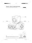
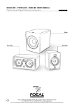
THIS INFORMATION TO BE PROVIDED UPON RECEIPT OF THEORY OF OPERATION SOURCE DATA AND
BLOCK DIAGRAM.
Elliptical Edge Service Manual
1.7
~JI:I,BYUNISEN,
Sec,ticn 2 .
INC._
®TiMC
Preventive Maintenance
Schedules
Performing regular scheduled preventive maintenance is essential in keeping your Elliptical Edge in top operating
condition. Without preventive maintenance, normal wear and tear may cause cumulative effects, such as misalignment and early replacement of parts.
This section provides a list of factory-recommended preventive maintenance requirements, along with detailed procedures for performing each task.
Contents
Preventive Maintenance Chart
2.2
Shuttle Alignment
2.3
Stride Belt Adjustment
2.4
Crank Belt Adjustment
2.E
Elliptical Edge Service Manual
2.1
gJr:l,SYUNISEN,INC.-
®1iIIlC
Preventive Maintenance Chart
The Preventive Maintenance Chart lists the scheduled maintenance tasks for the Elliptical Edge. The chart lists the
time interval when each procedure should be performed, and provides the general steps necessary to perform the
task. In some cases, the chart references detailed maintenance procedures provided later in the section.
=
=
=
D Daily; W Weekly; Q Quarterly (depending on the amount of use, Quarterly procedures may need to
be performed more frequently).
INTERVAL
D
W
Q
PROCEDURE
•
Clean dust and dirt from the unit using a soft, clean cloth dampened with a non-abrasive liquid
cleaner. Give particular attention to the display panel, handrails and heart rate grips (if used).
•
Clean dust, dirt, oils or other contaminants from inside the skate rails (the shuttle tracks), and on
the shuttle rollers, using a soft, clean cloth and a non-abrasive liquid cleaner. If needed, remove
stubborn accumulations by scrubbing with a soft-bristle brush (such as a toothbrush). NEVER use
a wire brush or any abrasive material to clean the skate rails or shuttle rollers.
IMPORTANT: Regular cleaning of the skate rails and shuttle rollers is CRITICAL to proper operation of the unit. Accumulations of dust and dirt on the skate rails or shuttle rollers can result in
rough operation, misalignment of the shuttles and excessive wear on the skate rails and shuttle
rollers.
2.2
•
Vacuum the floor under and around the unit. MAKE SURE that the unit is at its maximum elevation when vacuuming (or move the unit to another location).
•
Check the display panel and handrails to ensure they are securely attached to the unit. Retighten
the screws as needed.
•
Inspect the Sport Utility Display panel for evidence of wear. Contact STAR TRAC Customer
Support if replacement of the Sport Utility Display panel is necessary.
•
Check each shuttle for misalignment or excessive sideplay. Realign the shuttles as needed (see
Shuttle Alignment, page 2.3).
•
Check each stride belt for proper tension. Adjust the stride belt tension as needed (see Adjusting
Stride Belt Tension, page 2.4).
•
Check the crank belt for proper tension. Adjust the crank belt tension as needed (see Adjusting
Crank Belt Tension, page 2.5).
Elliptical Edge Service Manual
m-Jr:IrSYUNISEN, INC._
Shuttle . Alignment
0_0
o®liMC
Misaligned shuttles can cause rough operation, excessive noise during use, and uneven or early wear of the skate
rails and shuttle rollers.
The center rollers on each shuttle are equipped with eccentric cams which allow the shuttles to be adjusted to remove side play.
Tools Required:
Flat head screwdriver
Check the shuttle alignment:
1.
Grasp the shuttle with one hand, and rock the shuttle from side to side on the skate rail.
2.
There should be little or no evidence of movement (sideplay). The shuttle rollers should fit snugly inside the
skate rails.
3.
If excessive sideplay is noted, realignment of the shuttle(s) is necessary.
Realign the shuttle(s):
1.
Grasp the shuttle with one hand, and rock the shuttle from side to side on the skate rail. Determine whether one
or both sides of the shuttle show signs of excessive sideplay.
2.
Using flat head screwdriver, rotate the shuttle center roller screw a quarter turn clockwise. Recheck the shuttle
for sideplay.
3.
If sideplay has increased, adjust the roller screw counterclockwise. If sideplay has decreased, continue to adjust
the roller screw, a quarter turn at a time, until sideplay has been removed.
Elliptical Edge Service Manual
2.3
m-.Jr:IrSYUNISEN"NC.-
®liIIlC
Stride Belt Adjustment
Check and adjust the tension of each stride belt separately.
Tools Required:
Phillips head screwdriver
1-in. open-end wrench
Check the stride belt tension:
1.
Hold the skate rail with one hand so it does not move.
2. With your other hand, try to move the shuttle back and forth along the skate rail.
3.
If the shuttle DOES NOT move, stride belt tension does not need to be adjusted. If the shuttle DOES move,
stride belt tension must be adjusted.
Adjust stride belt tension:
1.
Using Phillips head screwdriver, remove the four Phillips head screws from the rear shroud filler panel.
2.
Remove the panel from the rear shroud.
3.
Using 1-in. open-end wrench, adjust the stride belt pulley nut clockwise, as needed, to increase stride belt tension.
Recheck the shuttle for movement along the skate rail. Continue to adjust the stride belt pulley nut until proper
stride belt tension is obtained.
5.
Position the rear shroud filler panel on the rear shroud.
6.
Using Phillips head screwdriver, secure the filler panel to the rear shroud with the four Phillips head screws.
2.4
Elliptical Edge Service Manual
m-.Jr:I..SYUNISEN,INC._
Crank Belt-·Adjustment·"
®liII\C'
Tools Required:
Phillips head screwdriver
9/16-in. open-end wrench
Belt tensioner gauge
Remove the front shroud:
1.
Using Phillips head screwdriver, remove the eight Phillips head screws from the front shroud.
2.
Lift the front shroud off the unit.
Check the crank belt tension:
1.
Using belt tensioner gauge, check that crank belt tension is 80 pounds.
2.
If a belt tensioner gauge is not available, check the crank belt tension by pressing down hard on top of the belt,
midway between the transmission idler pulley and the crank pulley. The belt should deflect between 3/8-in.-1/2in. (9.5-12.5 mm).
3.
If crank belt tension is less than 80 pounds, the crank belt must be adjusted.
Re-tension the crank belt:
1.
Using 9/16-in. open-end wrench, loosen the transmission idler tension nut to allow adjustment of the transmission idler tension bolt.
1.
Using 9/16-in. open-end wrench, tighten the transmission idler tension bolt to increase crank belt tension.
2.
Using belt tensioner gauge to check crank belt tension, continue to tighten the transmission idler tension bolt to
achieve 80 pounds tension.
•
3.
If a belt tensioner gauge is not available, check the crank belt tension by pressing down hard on top of the
belt, midway between the transmission idler pulley and the crank pulley. The belt should deflect between
3/8-in.-1/2-in. (9.5-12.5 mm).
Once the correct crank belt tension is obtained, tighten the transmission idler tension nut SECURELY using
9/16-in. open-end wrench.
Install the front shroud:
1.
Install the front shroud in position on the unit.
2.
Using Phillips head screwdriver, secure the front shroud to the unit with the eight Phillips head screws.
Elliptical Edge Service Manual
2.5
,m-.J[:I,SYUNISEN.INC._
Section 3
®liIIlC
Diagnostics
The Elliptical Edge contains several customizing and diagnostics features. The customizing feature allows you to
tailor unit operation to suit your particular needs. Diagnostics features let you view accumulated data related to machine usage, and check critical operating parameters as an aid in maintenance and troubleshooting.
These features include:
•
Diagnostic LEOs - Provide and indication of the operating status of the Load Control Board (LCB) and the alternator.
•
Display Maintenance Mode - Displays start-up and shut-down service messages as a result of self-test or
wh:m scheduled periodic maintenance is required.
•
Display Settings Mode - Lets you modify certain operating and display settings for the unit.
•
Service Settings Mode - Displays accumulated statistical data related to machine usage.
•
Service Messages - Display during machine use if certain electrical failures or out-of-tolerance conditions are
detected.
•
System Measurements Mode - Lets you monitor critical electrical parameters under both idle and in-use conditions.
Contents
Diagnostic LEDs
:................................................................................
3.2
Display Maintenance Mode
3.3
Display Settings Mode
3.4
Service Settings Mode
3.6
Service Messages :............................................................................................................................................
System Measurements Mode
Elliptical Edge Service Manual
_~.................................................................................................
3.7
3.8
3.1
DiagnosticLEDs
The Load Control Board (LCB) is equipped with three diagnostic LEOs. These LEOs provide indications of the operating status
of the LCB and the alternator.
The LCB diagnostic LEOs function as follows:
LED
FUNCTION
D2
This Led provides a steady series of flashes, at 20-per-second, indicating communication between the
LCB and the display panel is functional. If this LED is off or flashes erratically, replacement of the LCB,
the display panel or the communication cable may be required.
D3
This LED provides a steady series of flashes, at one-per-second, indicating the LCB microprocessor is
functional and the loop circuit is operating. If this LED is off or flashes erratically, replacement of the LCB
may be required.
D13
This LED is normally off. If alternator output voltage exceeds 19 volts, the LED lights steady on. This condition will also cause the "Needs Service" message to display (see Display Maintenance Mode for details).
NOTE: The diagnostic LEOs provide a general indication of certain equipment malfunctions. Refer to Section 4,
Troubleshooting to aid in locating the most likely cause of the problem.
3.2
Elliptical Edge Service Manual
.m-.JI=I..SYUNISEN.INC._
Display Maintenance Mode
®mIlC
The Elliptical Edge displays start-up or shutdown service messages if a display code is detected during use, or when
periodic maintenance is due.
Service Messages at Start-up
The unit performs a self-test at the beginning of every workout. The self-test is initiated as soon as operation of the
unit begins, and continues throughout the duration of the workout. If a failure in an electronic circuit or component is
detected, one of the following messages will display:
Key Down
One or more keys on the keypad(s) are stuck in the depressed (on) position; maintenance
service is required. Call Star Trac Customer Support for assistance.
Needs Service
Self-test has detected an electronic component failure; maintenance service is required.
Call Star Trac Customer Support for assistance. Specific service messages describing the
equipment malfunction or failure can be accessed and viewed using the Service Settings
feature. Additional troubleshooting information is provided in Section 4.
Service Message at Shutdown
The Elliptical Edge displays a "Time for Service" message when a periodic (preventive) maintenance procedure is
due. This message displays for 2-3 seconds at the end of a workout session. Call Star Trac Customer Support for
assistance. Preventive maintenance procedures are outlined in Section 2.
Elliptical Edge Service Manual
3.3
Display Settings Mode
The Display Settings Mode lets you view and modify several unit settings, which affect the way the machine operates during a workout. Use the keypad to enter the Display Settings Mode, view the current settings and make any
desired changes.
To enter the Display Settings Mode:
1.
Press and hold the "Enter", "0" and "1" keys at the same time.
2•. While continuing to' hold the "Enter" and "0" keys; release the "1" key. The unit will beep once, and the message
"Display Settings" will show in the upper information display.
3.
Release the "Enter" and "0" keys.
Once the unit is in the Display Settings Mode, use the keypad to select and enter changes to unit settings:
KEY
"Scroll" Key
FUNCTION
Press the "Scroll" key to scroll through the display settings and select the setting you wish to
view or change (for each setting, the current value is displayed in the upper information window). Pressing and holding the "Scroll" key will scroll continuously through the available settings.
"Up-Down Arrow" Use the "Up-Down Arrow" keys to scroll through the available values for the setting and to select a new value. When a new value for the setting has been selected, press the "Scroll" key to
Keys
save the new value and advance to the next setting.
NOTE: To return display settings to their original values after changes have been made and
saved, you must MANUALL Y re-enter the factory-default settings.
"Enter" Key
3.4
Press the "Enter" key to exit the Display Settings Mode and return to the standard operating
mode.
Elliptical Edge Service Manual
.m-m..SYUNISEN,INC._
®liIIlC
Display Settings Mode
The following display settings may be changed using the keypad as previously described:
DESCRIPTION
SETIING
DEFAULT VALUE
Maximum Work Time
Sets the maximum workout time, in minutes.
60 minutes
Heart Rate
Enables/disables the Polar heart rate pickup
Polar
Units
Sets the units display to English or Metric:
English
Weight
•
English - distance is displayed in tenths of a mile; speed is
displayed in miles-per-hour; weight is displayed in pounds
•
Metric - distance is displayed in tenths of a kilometer; speed is
displayed in kilometers-per-hour; weight is displayed in kilograms.
Sets the weight displayed as default when a preset program is
selected. This value is a default only; users are prompted to enter
their actual weight (used for calculating total calories burned).
155
NOTE: When setting metric units, weight must be set at 70 kg.
Elliptical Edge Service Manual
3.5
Service Setting's·
The Elliptical Edge records and stores usage data which may be used as an aid in maintaining the unit and diagnosing malfunctions. The Service Settings Mode lets you view this usage data, as well as software version numbers
and the serial number and date of manufacture for the unit.
To enter the Service Settings Mode:
1.
Press and hold the "Enter", "0" and "2" keys at the same time.
2.
While continuing to hold the "Enter" and "0" keys, release the "2" key. The unit will beep once, and the message
"Service Settings" will show in the upper information display.
3.
Release the "Enter" and "0" keys.
Once the unit is in the Service Settings Mode, use the keypad to view service settings, service messages, or system
measurements: .
The following stored data may be viewed while in the Service Settings Mode:
ITEM
DESCRIPTION
Display Version
Version of software currently installed in the display.
LCB Version
Version of software currently installed in the Load Control Board.
Serial#
Serial number of the unit.
Manufacture Date
Unit manufacture date (displayed as DDMMYY).
Workout Hours
Total number of operating hours accumulated on the unit to date.
Workout Distance
Total number of distance units accumulated on the machine to date. Distance units are
displayed in either miles or kilometers (depending on the "Units" selection (English or Metric) chosen in "Display Settings".
Battery Hours
Total number of hours the battery has been used under power (displayed in thousands of
hours). Need to reset to zero when battery replaced.
Last Keystrokes
Displays the last five keys pressed prior to a software or system failure.
3.6
Elliptical Edge Service Manual
STJI=I..SYUNISEN,INC._
®1iIIlC
Service Messages
The Elliptical Edge self-test function monitors the electronics while a workout is in progress. If a malfunction or failure
in a monitored circuit occurs during a workout, the "Needs Service" message displays (as described in Display
Maintenance Mode), and a specific service message is set. Service message can be accessed and viewed from the
Service Settings Mode.
To view Service Messages:
•
On entering the Service Settings Mode, press the "S" key while in "service settings". "Service message" will display in the upper information display.
•
Press the "Scroll" key to view service messages (if any have been set). Pressing and holding the "Scroll" key
will advance through all service messages.
•
Press the "Enter" key to exit Service Messages and return to the Service Settings Mode.
The following service messages may be set by the self-test function:
MESSAGE
DEFINITION
No Communication
A communication failure has occurred between the upper display and the Load Control
Board (LCB). Communications cable or LCB replacement may be required.
No Alternator Output
The alternator is not producing an output voltage (the unit will not provide a
load/workout to the user). Alternator, load resistor or alternator cable harness replacement may be required.
Alternator Field Open
The alternator field has an open circuit. Alternator, alternator cable harness or LCB
replacement may be required.
No Load
The alternator is working, but the unit is not providing a load (workout) to the user. Alternator cable harness or LCB replacement may be required.
Low Battery
The battery charge voltage is low. This may be a result of low usage. The battery can
be recharged either by operating the machine by connecting the external wall-powered
power pack and the machine is in use for several hours. With the machine not in use
the recharging of the battery will take 24 hours to reach full charge.
NOTE: If the "Low Battery" message is set frequently, battery replacement or charging
system service may be required.
Elliptical Edge Service Manual
3.7
~Jr:I,BYUNISENIINC'-
®liUlC
System Measurements Mode
The System Measurements Mode lets you measure critical voltages in the battery/alternator circuits, under both idle
and operating conditions.
To enter the System Measurements Mode:
•
On entering the Service Settings Mode, press the "8" key while in "service settings". "Measurements" will display in the upper information display.
•
Press the "Scroll" key to view the system measurements available.
•
Press the "Enter" key to exit the System Measurements Mode and return to the Service Settings Mode.
Once the unit is in the System Measurements Mode, use the [Arrow Keys] to select the desired system measurement.
The following voltage measurements may be taken while in the System Measurements Mode:
MEASUREMENT
Battery Voltage
Alternator Voltage
DESCRIPTION
Measures and displays battery output voltage while the unit is idle. Output voltage for a
normal battery should range between 6.2-7.7 volts.
•
Output voltage below 6.2 volts indicates a low battery charge or a damaged battery.
•
Output voltage above 7.7 volts indicates a fault in the Load Control Board.
Measures and displays alternator output voltage while the unit is in use. To check the alternator output voltage:
•
Pedal the unit at a speed above 1.5 miles-per-hour.
•
Alternator output voltage should range between 11.5-13.5 volts. Voltages outside this
range indicate a fault in the Load Control Board.
Wall Power
Measures and displays the voltage delivered to the unit from an optional external wallpowered power pack while the unit is idle. An acceptable power pack voltage will range
between 11.0-18.0 voltage. The power pack should be replaced if the voltage is outside
this range.
Load Voltage
Measures and displays the voltage generated across the workout loading resistor while the
unit is in use. To measure the load voltage:
•
•
3.8
Pedal the unit at a speed above 1.5 miles-per-hour.
Load voltage should range between 1.0-10.0 volts. Voltages outside this range indicate a fault in the Load Control Board. A lower voltage indicates a high resistance
which is normal.
Elliptical Edge Service Manual
Section 4
.srJl=l..SYUNISEN"NC._
®lWlC
Troubleshooting
The Elliptical Edge incorporates built-in self-test and diagnostic features which assist in diagnosing electrical system
problems. Section 3: Diagnostics contains the procedures for using these self-test and diagnostic features.
This section contains troubleshooting information for mechanical problems which may occur as a result of normal
usage of the Elliptical Edge. Troubleshooting information is presented in chart form. The Troubleshooting Chart
identifies symptoms of problems which may occur, lists the most probable cause(s) for the problem, and provides
suggested remedies to return the unit to operating condition.
Contents
Troubleshooting Chart
Elliptical Edge Service Manual
4.2
4.1
ST..n:I..SYUNISEN"NC._
®TiVlC
SYMPTOM
Shuttle is loose (forward and backward movement on skate rail)
Troubleshooting Chart
PROBABLE CAUSE
1. The stride belt is worn or has
stretched.
SUGGESTED REMEDY
1. Adjust the stride belt tension (see
Stride Belt Adjustment, page 2.4)
2. Replace the stride belt (see
Stride Belt Replacement, page
5.18)
2. The clutch bearing is slipping.
1. Replace the transmission assembly (see Transmission Bearings Replacement, page 5.20)
2. Replace the transmission shaft
(see Transmission Bearings Replacement, page 5.20)
Shuttle is loose (up and down
movement or sideplay on skate
rail)
1. The shuttle out of adjustment
1. Adjust the shuttle's eccentric rollers (see Shuttle Adjustment,
page 2.3)
2. The shuttle rollers are worn
1. Adjust the shuttle's eccentric rollers (see Shuttle Adjustment,
page 2.3)
2. Replace the shuttle (see Shuttle
Replacement, page 5.13)
Front of skate rail falls rapidly with
little or no resistance
1. The crank belt is loose or worn.
1. Re-tension the crank belt as
needed (see Crank Belt Adjustment, page 2.5)
2. Replace the crank belt (NO
PROCEDURE RECEIVED FOR
CRANK BELT REPLACEMENT)
2. The alternator belt is loose or
worn.
1. Retension the alternator belt as
needed (NO PROCEDURE
RECEIVED FOR ALTERNATOR
BELT RETENSIONING)
2. Replace the alternator belt (NO
PROCEDURE RECEIVED FOR
ALTERNATOR BELT REPLACEMENT)
4.2
Elliptical Edge Service Manual
,m-Jt:I,SYUNISEN"NC._
Crank Belt Adjustment
SYMPTOM
PROBABLE CAUSE
Crank pulley makes excessive noise
during use
1. The crank pulley is loose on the
Shuttle makes noise as it move
along skate rail
1. There is dirt or debris build-up on
crank shaft.
the shuttle rollers.
2. There is dirt or debris build-up in
the skate rail tracks.
Elliptical Edge Service Manual
®mAC
SUGGESTED REMEDY
1. Tighten the crank pulley Allen
screws (see Crank Bearings Replacement, page 5.22)
1. Clean the shuttle rollers (see
Preventive Maintenance Chart,
page 2.2)
1. Clean the skate rails (see Preventive Maintenance Chart, page
2.2)
2.3
~.Jt:I..BYUNISEN,
INC._
®liIIlC
Parts Replacement
This section contains parts replacement procedures for assemblies and components of the Elliptical Edge which are
authorized for in-field replacement. Parts should be replaced ONLY when indicated by diagnosis and troubleshooting. There are no parts which are to be replaced as a part of scheduled preventive maintenance.
Contents
Display Panel Replacement..
5.2
Communication Cable Replacement
5.3
Display Power Cable Replacement
5.5
Cable Harness Replacement
5.7
LCB Replacement
5.9
Battery Replacement
5.11
Shuttle Replacement
5.12
Skate Rail Replacement
5.15
Stride Belt Replacement
5.:?
Transmission Bearings Replacement
5.24
Crank Bearings Replacement
5.27
Elliptical Edge Service Manual
5.1
gJl=l,SYUNISEN.,NC._
®lWlC
Display Panel Replacement
Tools Required:
3/32-in. Allen Wrench
Remove the display panel:
NOTE: Use one hand
to support the display
panel during removal.
NOTE: DO NOT pull
on the wires when disconnecting the cable
from the display
panel.
1.
Using 3/32-in. Allen wrench, remove the seven Allen screws from the back of the display
panel. BE SURE to support the display panel after the Allen screws have been removed.
2.
CAREFULLY disconnect the communication cable from display panel connector J4 and
the display power cable from display panel connector J7, by grasping and pulling the cable connectors.
3.
Remove the display panel.
Install the display panel:
NOTE: Use one hand
to support the display
panel during installation.
1.
Place the display panel in position on the unit. BE SURE to support the display panel until
the Allen screws have been installed.
2.
CAREFULLY connect the communication cable and power cable to the display panel.
MAKE SURE the connectors are properly aligned when reconnecting. DO NOT force the
connectors.
NOTE: The cable connectors are keyed to
'ent improper con.ion.
3.
5.2
•
Connect the communication cable to display panel connector J4.
•
Connect the display power cable to display panel connector J7.
Using 3/32-in. Allen wrench, secure the display panel to the frame with the seven Allen
screws. Tighten the Allen screws firmly. DO NOT OVERTIGHTEN.
Elliptical Edge Service Manual
,g./l=l;SYUNISEN,INC._
Communication Cable Replacement
®liUlC
i
Tools and Materials Required:
Phillips head screwdriver
3/32-in. Allen wrench
Tape
Remove the front shroud:
1.
Using Phillips head screwdriver, remove the eight Phillips head screws from the front
shroud.
2.
Lift the front shroud off the unit.
Disconnect the communication cable from the LeB:
NOTE: DO NOTpulI
on the wires when disconnecting the communication cable from
the LeB.
1.
CAREFULLY disconnect the communication cable from LCB connector J1 by grasping
and pUlling the cable connector. See Diagram 8
DISCONNECT
Jl
"\
I
/
/
Diag.B
Remove the display panel:
1.
Using 3/32-in. Allen wrench remove the seven Allen screws from the back of the displt.'
panel. BE SURE to support the display panel after the Allen screws have been removed.
Elliptical Edge Service Manual
I
J
5.3
gJl=l,SYUNISEN1INC._
®1ftIlC
NOTE: Use one hand
to support the display
panel during removal.
NOTE: DO NOT pull
on the wires when disconnecting the cables
from the display panel.
NOTE: To prevent the
display power cable
from falling through the
display neck opening,
tape the display power
cable to the top of the
display neck.
Communication Cable Replacement
2.
CAREFULLY disconnect the communication cable from display panel connector J4 and
the display power cable from display panel connector J7, by grasping and pulling the cable connectors.
3.
Remove the display panel.
Install the communication cable:
1.
Tape one end of the new communication cable to the bottom (LCB end) of the old communication cable.
2.
Using the old communication cable as a routing guide, GENTLY pull the new communication cable up through the display neck. The communication cable should route
smoothly and easily through the display neck. DO NOT force the cable through the neck.
3.
Remove the tape and separate the new communication cable from the old communication
cable.
Install the display panel:
NOTE: Use one hand
to support the display
11 during instal/a-
1.
Place the display panel in position on the unit. BE SURE to support the display panel until
the Allen screws have been installed.
2.
CAREFULLY connect the communication cable and power cable to the display panel.
MAKE SURE the connectors are properly aligned when reconnecting. DO NOT force the
connectors.
NOTE: The cable
connectors are keyed
to prevent improper
connection.
3.
•
Connect the communication cable to display panel connector J4.
•
Connect the display power cable to display panel connector J7.
Using 3/32-in. Allen wrench, secure the display panel to the frame with the seven Allen
screws. Tighten the Allen screws firmly. DO NOT OVERTIGHTEN.
Connect the communication cable to the LCB:
1.
NOTE: The cable
connector is keyed to
prevent improper connection.
5.4
CAREFULLY connect the communication cable to LCB connector J1. MAKE SURE the
connector is properly aligned when reconnecting. DO NOT force the connector.
Install the front shroud:
1.
Install the front shroud in position on the unit.
2.
Using Phillips head screwdriver, secure the front shroud to the unit with the eight Phillips
head screws.
Elliptical Edge Service Manual
Display Power Cable Replacement
Tools and Materials Required:
Phillips head screwdriver
3/32-in. Allen wrench
Tape
Remove the front shroud:
1.
Using Phillips head screwdriver, remove the eight Phillips head screws from the front
shroud.
2.
Lift the front shroud off the unit.
Disconnect the display power cable from the LeB:
NOTE: DO NOT pull
on the wires when disconnecting the communication cable from
the LeB.
1.
CAREFULLY disconnect the display power cable from LCB connector J2 by grasping and
pulling the cable connector. See Diagram C.
\
\
\
)
/
/
Diag. C
Remove the display panel:
1. Using 3/32-in. Allen wrench, remove the seven Allen screws from the back of the displpanel. BE SURE to support the display panel after the Allen screws have been remov\.
Elliptical Edge Service Manual
5.5
~.n:I,BYUNISEN.INC._
®lWlC
NOTE: Use one hand
to support the display
panel during removal.
NOTE: DO NOT pull
on the wires when disconnecting the cables
from the display panel.
NOTE: To prevent the
communication cable
from falling through the
display neck opening,
tape the communication cable to the top of
the display neck.
Display Power Cable Replacement
2.
CAREFULLY disconnect the communication cable from display panel connector J4 and
the display power cable from display panel connector J7, by grasping and pulling the cable connectors.
3.
Remove the display panel.
Install the display power cable:
1.
Tape one end of the new display power cable to the bottom (LCB end) of the old display
power cable.
2.
Using the old display power cable as a routing guide, GENTLY pull the new display power
cable up through the display neck. The display power cable should route smoothly and
easily through the display neck. DO NOT force the cable through the neck.
3.
Remove the tape and separate the new display power cable from the old display power
cable.
Install the display panel:
E: Use one hand
.:iUpport the display
panel during installation.
1.
Place the display panel in position on the unit. BE SURE to support the display panel until
the Allen screws have been installed.
2.
CAREFULLY connect the communication cable and power cable to the display panel.
MAKE SURE the connectors are properly aligned when reconnecting. DO NOT force the
connectors.
NOTE: The cable
connectors are keyed
to prevent improper
connection.
3.
•
Connect the communication cable to display panel connector J4.
•
Connect the display power cable to display panel connector J7.
Using 3/32-in. Allen wrench, secure the display panel to the frame with the seven Allen
screws. Tighten the Allen screws firmly. DO NOT OVERTIGHTEN.
Connect the display power cable to the LCB:
1.
NOTE: The cable
connector is keyed to
prevent improper connection.
5.6
CAREFULLY connect the display power cable to LCB connector J2. MAKE SURE the
connector is properly aligned when reconnecting. DO NOT force the connector.
Install the front shroud:
1.
Install the front shroud in position on the unit.
2.
Using Phillips head screwdriver, secure the front shroud to the unit with the eight Phillips
head screws.
Elliptical Edge Service Manual
ST'Jt:l.SYUNISEN,INC._
®lftIlCi
Cable Harness Replacement
Tools Required:
Phillips head screwdriver
1/2-in. open-end wrench
Needle-nose clippers
Tie straps (20 req'd)
Remove the front shroud:
1. Using Phillips head screwdriver, remove the eight Phillips head screws from the front
shroud.
2.
Lift the front shroud off the unit.
Disconnect the cable harness from the LeB:
NOTE: DO NOT pull on
the wires when disconnecting the cables from
the LeB.
1.
CAREFULLY disconnect the following cables from the LCB by grasping and pulling the
cable connectors: See Diagram D.
•
Disconnect the battery cable from LCB connector J3.
•
Disconnect the alternatorlload resistor cable LCB connector J4.
•
Disconnect the external power cable LCB connector J5.
/
-~
'" \
1
/
/
/
Diag. D
Disconnect the cable harness from the alternator:
1.
Using 1/2-in. open-end wrench, disconnect the following wires from the alternator terminals:
•
Disconnect the two red wires from the alternator B terminal.
•
Disconnect the black wire from the alternator E terminal.
Elliptical Edge Service Manual
5.7
g.n:l..SYUNISEN"NC._
®lWlC
NOTE: Note the location of the 20 tie straps
to aid in reinstallation
Cable Harness Replacement
•
Disconnect the yellow wire from the alternator EXC terminal.
•
Disconnect the white wire from the alternator P terminal.
•
Disconnect the green wire from the alternator S terminal.
2.
Using needle-nose clippers, cut and remove the 20 tie straps securing the cable harness
to the frame; remove the cable harness.
3.
Separate the red (+) and black (-) battery cables from the cable harness.
Remove the load resistor:
1.
Using Phillips head screwdriver, remove the two Phillips head screws securing the load
resistor to the frame; remove the load resistor.
Install the load resistor:
1.
Using Phillips head screwdriver, secure the new load resistor to the frame with two Phillips head screws. TIGHTEN THE SCREWS SECURELY.
Connect the cable harness to the alternator:
NOTE: The cable
connectors are keyed
to prevent improper
connection.
1.
Reroute the new cable harness and the red (+) and black (-) battery cables along the
frame. Use the 20 tie straps to secure the cable harness and battery cables to the frame
at the locations noted during removal.
2.
Using 1/2-in. open end wrench, connect the following wires to the alternator terminals:
TIGHTEN THE WIRE CONNECTION SECURELY.
•
Connect the two red wires to the alternator B terminal.
•
Connect the black wire to the alternator E terminal.
•
Connect the yellow wire to the alternator EXC terminal.
•
Connect the white wire to the alternator P terminal.
•
Connect the green wire to the alternator S terminal.
Connect the cable harness to the LCB:
1.
CAREFULLY connect the following cables to the LCB. MAKE SURE the connectors are
properly aligned when reconnecting. DO NOT force the connectors.
•
Connect the battery cable to LCB connector J3.
•
Connect the alternator/load resistor cable to LCB connector J4.
•
Connect the external power cable to LCB connector J5.
Install the front shroud:
5.8
1.
Install the front shroud in position on the unit.
2.
Using Phillips head screwdriver, secure the front shroud to the unit with the eight Phillips
head screws.
Elliptical Edge Service Manual
,m-Jt=I,.SYUNISEN,INC._
®1iVlC \
Load Control Board Replacement
Tools Required:
Phillips head screwdriver
Remove the front shroud panel:
1. Using Phillips head screwdriver, remove one Phillips head screw from the front shroud
panel. Remove the front shroud panel to gain access to the LCB.
Remove the LeB:
NOTE: DO NOT pull
on the wires when disconnecting the cables
from the LeB.
1. CAREFULLY disconnect the following cables from the LCB by grasping and pUlling the
cable connectors: See Diagram E.
•
Disconnect the communication cable from LCB connector J 1.
•
Disconnect the display power cable from LCB connector J2.
•
Disconnect the battery cable from LCB connector J3.
•
Disconnect the alternatorlload resister cable from LCB connector J4.
•
Disconnect the external power cable from the connector J5.
•
Disconnect the Fitlinxx cable from LCB connector J6.
-
/
I
/
/
Diag. E
Elliptical Edge Service Manual
5.9
gJl=l,.BYUNISEN,INC._
®liIIlC
NOTE: Use one hand
to support the LCa
when removing the
bottom Phillips head
screw from the LCa.
Load Control Board Replacement
2.
Using Phillips head screwdriver, remove the two top Phillips head screws securing the
LCB to the frame.
3.
Using Phillips head screwdriver, remove the bottom Phillips head screw securing the LCB
to the frame. Remove the LCB.
Install the LeB:
NOTE: Use one hand
to support the LCa
while installing the
three Phillips head
screws.
NOTE: The cable
connectors are keyed
to
prevent improper connection.
1.
Support the new LCB in position on the frame. Using Phillips head screwdriver, install the
top two Phillips head screws securing the LCB upper bracket to the frame. Install the
bottom Phillips head screw securing the LCB lower bracket to the frame. Tighten the
three screws firmly. DO NOT OVERTIGHTEN.
2.
CAREFULLY connect the following cables to the LCB. MAKE SURE the connectors are
properly aligned when reconnecting,. DO NOT force the connectors.
•
Connect the communication cable to LCB connector J1.
•
Connect the display power cable to LCB connector J2.
•
Connect the battery cable to LCB connector J3.
•
Connect the alternator/load resistor cable to LCB connector J4.
•
Connect the external power cable to LCB connector J5.
•
Connect the Fitlinxx cable to LCB connector J6.
Install the front shroud panel:
5.10
1.
Position the front shroud panel on the front shroud.
2.
Using Phillips head screwdriver, secure the front shroud panel to the front shroud with
one Phillips head screw.
Elliptical Edge Service Manual
,g.JR,SYUNISEN.INC._
®1iIIlC
Battery Replacement
Tools Required:
Phillips head screwdriver
Remove the front shroud:
1.
Using Phillips head screwdriver, remove the eight Phillips head screws from the front
shroud.
2. Lift the front shroud off the unit.
Remove the battery:
NOTE: DO NOT pull
on the wires when disconnecting from the
battery.
1.
CAREFULLY disconnect the black (-) and red (+) lead wires from the battery terminals by
grasping and pulling the wire connectors.
2.
Using Phillips head screwdriver, remove the two screws securing the battery to the frame;
remove the battery. See Diagram F.
Diag. F
Install the battery:
NOTE: When installing
the battery, make sure
the negative (-) terminal is positioned at the
top.
1.
Position the new battery on the frame. Using Phillips head screwdriver, install the two
Phillips head screws through the battery to secure the battery to the frame. TIGHTEN
THE SCREWS FIRMLY.
2.
Connect the lead wires to the battery:
•
Connect the black (-) lead wire to the.top battery terminal marked (-)
•
Connect the red (+) lead wire to the bottom battery terminal marked (+).
Install the front shroud:
1.
Install the front shroud in position on the unit.
2. Using Phillips head screwdriver, secure the front shroud to the unit with the eight
Philli~
head screw~.
Elliptical Edge Service Manual
5.11
~JI=I,BYUNISEN,
/NC._
®liIAC
Shuttle Replacement
Tools Required:
Phillips head screwdriver
Needle nose plier
Flat head screwdriver
Y2-in Hex head socket
3/16-in. socket wrench
5/32-in. Allen wrench
NOTE: Remove and
install ONL Y ONE
shuttle at a time.
Remove the front shroud:
1.
Using Phillips head screwdriver, remove the eight Phillips head screws from the front
shroud.
2.
Lift the front shroud off the unit.
Remove the shuttle:
1.
Slide the shuttle completely forward on the skate rail.
2.
Using 3/16-in. hex head socket wrench, remove the four screws (from underneath the
shuttle) securing the footpad to the shuttle. Remove the footpad.
3.
Using 3/16-in. hex head socket wrench, remove the four screws (at the rear of the shuttle) securing the shuttle to the capture plates.
4.
Using needle nose pliers, CAREFULLY pull the two cotter pins out from the belt tension
pulley (at the rear of the unit). See Diagram G.
5.
Using needle nose pliers, CAREFULLY pull the belt tension anchor pin out from the belt
tension pulley. See Diagram H.
\
\
f
(
~==--------
~-t-REMOY-E
\
------
" \LJ=0.
\
-:';
~
/"
,,
\
\
\
(
\
\,
/
\
,
:- ...........
Elliptical Edge Service Manual
----5.12
Shuttle Replacement
--------'1"""-------------------------------------::/ -NOTE: Adjust the position of the skate rail as
needed to allow removal
of the crank arm shaft.
6.
Using 1/2-in. hex head socket wrench and 1/2-in, open-end wrench, remove the front
stride belt pulley (and bolt) from inside the skate rail. See Diagram I.
STRIDE BELT PULLEY~
NOTE: MAKE SURE
the two Allen screws
engage the flats on the
crank arm shaft.
NOTE: You may need
to adjust the shuttle to
remove excess sideplay (see Section 2 for
details).
5.13
{.
7.
5
@
o
I
Using 5/32-in. Allen wrench, remove the two Allen screws from the crank arm. See Dia
gram J.
5.
CAREFULLY slide the crank arm shaft and two nylon washers out of the skate rail. BE
CAREFUL notto lose the two nylon washers.
6.
Slide the shuttle forward and off of the skate rail.
Elliptical Edge Service Manual
m-.ll=lrSYUNISEN"NC._
Shuttle Replacement
®1ftIlC
Install the shuttle:
NOTE: MAKE SURE
the two Allen screws
engage the flats on the
crank arm shaft.
NOTE: You may need
to adjust the shuttle to
remove excess sideplay (see Section 2 for
details).
1.
Slide the new shuttle on from the front of the skate rail.
2.
Slide the shuttle along the skate rail and align the holes in the back of the shuttle with the
holes in the captive plates.
3.
Using 3/16-in. hex head socket wrench, secure the shuttle to the capture plates with the
four screws. TIGHTEN THE SCREWS SECURELY.
4.
Install one nylon washer on the crank arm shaft. CAREFULLY insert the crank arm shaft
through the skate rail, then install the remaining nylon washer on the crank arm shaft.
5.
Insert the crank arm shaft through the crank arm.
6.
Rotate the crank arm shaft, as needed, until the flats on the shaft are aligned with the
holes in the crank arm.
7.
Using 5/32-in. Allen wrench, install the two Allen screws in the crank arm. TIGHTEN THE
SCREWS SECURELY.
8.
Install the front stride belt pulley through the stride belt and rail. Using %-in socket head
and a %-in open end wrench, secure the front stride belt pulley to the skate rail with the
bolt. TIGHTEN THE SOLT SECURELY.
9.
Insert the belt tension anchor pin in the belt tension pulley through the loop in the stride
belt. Install the two cotter pins in the belt tension anchor pin.
10. Place the footpad in position on the shuttle. Using 3/16-in. hex head socket wrench, install
the four Allen screws (from underneath the shuttle) to secure the footpad to the shuttle.
TIGHTEN THE SCREWS SECURELY.
Install the front shroud:
1.
Install the front shroud in position on the unit.
2.
Using Phillips head screwdriver, secure the front shroud to the unit with the eight Phillips
head screws.
Elliptical Edge Service Manual
5.14
Skate RaiLReplacement··
•
Tools Required:
Phillips head screwdriver
7/16-in. socket wrench
1/2-in. socket wren
1/2-in. open-end wrench
3/16-in. Allen wrench
5/32-in. Allen wrench
1/8-in. Allen wrench
Needle nose pliers
NOTE: Remove and
instafl ONL Y ONE
skate rail at a time.
Remove the front shroud:
1.
Using Phillips head screwdriver, remove the eight Phillips head screws from the front
shroud.
2.
Lift the front shroud off the unit.
Remove the rear shroud:
1.
Using Phillips head screwdriver, remove the eight Phillips head screws from the rear
shroud.
2.
Lift the rear shroud off the unit.
Remove the skate rail:
1.
Slide the shuttle completely forward on the skate rail.
2.
Using 3/16-in. hex head socket wrench, remove the four screws (from underneath the
shuttle) securing the footpad. to the shuttle. Remove the footpad.
3.
Using 3/16-in. hex head socket wrench, remove the four screws (at the rear of the shuttle) securing the shuttle to the capture plates.
4.
Using needle nose pliers, CAREFULLY pull the section of the stride belt containing the
capture plates out through the access hole in the side of the skate rail.
5.
Using 1/8-in. Allen wrench, remove the three Allen screws from the top capture plate, and
separate the capture plates from the stride belt. See Diagram K.
Diag. K
Elliptical Edge Service Manual
5.15
~m..BYUNISEN,INC._
®liIIlC
Skate Rail Replacement
6.
Using needle nose pliers, CAREFULLY pull the two cotter pins out from the belt tension
pulley (at the rear of the unit). See Diagram L.
7.
Using needle nose pliers, CAREFULLY pull the belt tension anchor pin out from the belt
tension pulley. See Diagram M.
\
\
I
I
------
~-.L----- /
\
Diag. M
\
\
\
REMOVE
~
-"'\/------
'"
/
I
(
/
\
Diag. L
I
I
REMOVE
8.
/
Using 7/16-in. hex head socket wrench and 3/16- in. Allen wrench, remove the top two
bolts from the belt guide bracket. Once the bolts are removed, CAREFULLY dislodge the
stride belt from the groove in the guide bracket. See Diagram N.
----
FRONT VIEW
Diag. N
5.16
Elliptical Edge Service Manual
m-'1t=IrSYUNISEN,INC._
®lftIlC
Skate Rail Replacement
9.
-
Using 1/2-in. hex head socket wrench and 1/2-in. open-end wrench, remove the rear
stride belt pulley (and bolt) from inside the skate rail. See Diagram O.
-----.
""'\
g
~
/
/
Diag.O
10. Using 1/2-in. hex head socket wrench and 1/2-in, open-end wrench, remove the front
stride belt pulley (and bolt) from inside the skate rail. See Diagram P.
ST,,:OE BELT PULLEY
o
Diag. P
NOTE: Adjust the position of the skate rail as
needed to allow removal of the crank arm
shaft.
11. Pull the stride belt out through the back of the skate rail.
12. Using 5/32-in. Allen wrench, remove the two Allen screws from the crank arm.
13. CAREFULLY slide the crank arm shaft and two nylon washers out of the skate rail. BE
CAREFUL not to lose the two nylon washers. See Diagram Q.
Diag.Q
Elliptical Edge Service Manual
5.17
,m-.Jt:IrSYUNISEN,INC._
®TiIIlC
Skate Rail Replacement
14. CAREFULLY slide the skate rail off the frame by pushing the skate rail forward and off
the front end.
15. Slide the shuttle off of the skate rail.
Reinstall the skate rail:
NOTE: MAKE SURE
the two Allen screws
engage the flats on the
crank ann shaft.
NOTE: When installing
the stride belt in the
skate rail, the punched
?/es in the belt face
p, the arrows point to
the rear of the skate
rail.
1.
Slide the shuttle onto the skate rail.
2.
Slide the skate rail on from the front of the frame, engaging the skate rail with the rollers
attached to the rear of the frame.
3.
Install one nylon washer on the crank arm shaft. CAREFULLY insert the crank arm shaft
through the skate rail, then install the remaining nylon washer on the crank arm shaft.
4.
Insert the crank arm shaft through the crank arm.
5.
Rotate the crank arm shaft, as needed, until the flats on the shaft are aligned with the
holes in the crank arm.
6.
Using 5/32-in. Allen wrench, install the two Allen screws in the crank arm. TIGHTEN THE
SCREWS SECURELY.
7.
Using 1/2-in. hex head socket wrench, secure the skate rail to the rear frame with two
bolts. TIGHTEN THE SOLTS SECURELY.
8.
Insert the stride belt into the skate rail (from the rear end) and route the stride belt through
the skate rail. MAKE SURE the belt is straight when installed in the skate rail.
9.
Install the front stride belt pulley in the stride belt. Using 1/2-in. hex head socket wrench
and 1/2-in. open end wrench, secure the front stride belt pulley to the skate rail with the
bolt. TIGHTEN THE SOLT SECURELY.
10. Install the rear stride belt pulley in the stride belt. Using 1/2-in. hex head socket wrench
and 1/2-in. open end wrench, secure the read stride belt pulley to the skate rail with the
bolt. TIGHTEN THE SOLT SECURELY:
11. Slide the shuttle forward on the skate rail until the shuttle rests against the front stride belt
pulley.
12. Using needle nose pliers, CAREFULLY pull the section of the stride belt with the three
holes out through the access hole in the side of the skate rail.
13. Assemble the capture plates on the stride belt, aligning the holes in the capture plates
with the holes in the stride belt.
14. Using 1/8-in. Allen wrench, secure the capture plates to the stride belt with the three Allen
screws. Insert the stride belt and capture plate back inside the skate rail.
15. Remove any extra slack from the stride belt by GENTLY pulling the stride belt out the rear
of the skate rail. MAKE SURE the stride belt is tight around both the front and rear stride
belt pulleys.
16. Insert the exposed end of the stride belt through the groove in the belt guide bracket.
17. Using 7/16-in. hex head socket wrench and 3/16-in. Allen wrench, secure the belt guide
bracket to the frame with the two bolts. TIGHTEN THE SOLTS SECURELY.
18. Slide the shuttle back along the skate rail and align the four holes in the rear of the shuttle
with the four holes in the capture plate. .
5.18
Elliptical -Edge Service Manual
m-JR,SYUN,SEN"NC._
Skate Rail Replacement> .
®1iIIlC
19. Using 3/16-in. hex head socket wrench, secure the shuttle to the capture plate with the
four screws. TIGHTEN THE SCREWS SECURELY.
NOTE: It may be necessary to adjust stride
belt tension following
skate rail replacement
(see Section 2 for details).
NOTE: You may need
to adjust the shuttle to
remove excess sideplay (see Section 2 for
details).
20. Route the free end of the stride belt around the belt tension pulley, and insert through the
pulley opening.
21. Insert the belt tension anchor pin in the belt tension pulley through the loop in the stride
belt. Install the two cotter pins in the belt tension anchor pin
22. Place the footpad in position on the shuttle. Using 3/16-in. hex head socket wrench, install
the four Allen screws (from underneath the shuttle) to secure the footpad to the shuttle.
TIGHTEN THE SCREWS SECURELY.
Install the rear shroud:
1.
Install the rear shroud in position on the unit.
2.
Using Phillips head screwdriver, secure the rear shroud to the unit with the eight Phillips
head screws.
Install the front shroud:
1.
Install the front shroud in position on the unit.
2.
Using Phillips head screwdriver, secure the front shroud to the unit with the eight PhilliPI'
head screws.
\
Elliptical Edge Service Manual
5.19
Stride Belt Replacement
Tools Required:
Phillips head screwdriver
7/16-in. socket or open-end wrench
1/2-in. socket wrench
1/2-in. open-end wrench
3/16-in. Allen wrench
1/8-in. Allen wrench
Needle nose pliers
NOTE: Remove and
install ONL Y ONE
stride belt at a time.
Remove the rear shroud:
1.
Using Phillips head screwdriver, remove the eight Phillips head screws from the rear
shroud.
2.
Lift the rear shroud off the unit.
Remove the stride belt:
1.
Using needle nose pliers, CAREFULLY pull the two cotter pins out from the belt tension
pulley (at the rear of the unit).
2.
Using needle nose pliers, CAREFULLY pull the belt tension anchor pin out from the belt
tension pulley. See Diagram R.
----
--..
'\
\
,/
\
I
\
I
'"
REMOVE/
"
5.20
/
" ............ ~
---- ...-/"'"'
"'
Diag. R
Elliptical -Edge Service Manual
g.ll=lrSYUNISEN.INC._
®1iIIlC'
Stride Belt Replacement,·
•
3.
Using 7/16-in. hex head socket wrench and 3/16- in. Allen wrench, remove the top two
bolts from the belt guide bracket. Once the bolts are removed, CAREFULLY dislodge the
stride belt from the groove in the guide bracket. See Diagram S•
.....
-----
FRONT VIEW
Diag. S
4.
Using 1/2-in. hex head socket wrench and 1/2-in. open-end wrench, remove the rear
stride belt pulley (and bolt) from inside the skate rail. See Diagram T.
----
/
/
5.
Diag. T
Using 3/16-in. hex head socket wrench, remove the four screws (from underneath the
shuttle) securing the footpad to the shuttle. Remove the footpad.
6.
Using 3/16-in. hex head socket wrench, remove the four screws (at the rear of the shuttle) securing the shuttle to the capture plates.
7.
Using needle nose pliers, CAREFULLY pull the section of the stride belt containing thL
capture plates out thrqugh the access hole in the side of the skate rail.
Elliptical Edge Service Manual
5.21
gJl=l,SYUNISEN, INC._
®liIIlC
8.
Stride Belt Replacement
Using 1/8-in. Allen wrench, remove the three Allen screws from the top capture plate, and
separate the capture plates from the stride belt. See Diagram U.
POINTS TOWARD FRONT
OF WELDED RAIL
Diag. U
9.
Using 1/2-in. hex head socket wrench and 1/2-in, open-end wrench, remove the front
stride belt pulley (and bolt) from inside the skate rail. See Diagram V.
o
I
Diag. V
10. Pull the stride belt out through the back of the skate rail.
Install the stride belt:
NOTE: W'hen installing
the stride belt in the
skate rail, the punched
holes in the belt face
up, the arrows point to
the rear of the skate
rail.
1.
Insert the stride belt into the skate rail (from the rear end) and route the stride belt through
the skate rail. MAKE SURE the belt is straight when installed in the skate rail. See DiagramW.
Diag.W
5.22
2.
Install the front stride belt pUlley in the stride belt. Using 1/2-in. hex head socket wrench
and 1/2-in. open end wrench, secure the front stride belt pulley to the skate rail with the
bolt. TIGHTEN THE SOLT SECURELY.
.
3.
Install the rear stride belt pulley in the stride belt. Using 1/2-in. hex head socket wrench
and 1/2-in. open end wrench, secure the read stride belt pUlley to the skate rail with the
bolt. TIGHTEN THE SOLT SECURELY.
4.
Slide the shuttle forward on the skate rail until the shuttle rests against the front stride belt
pulley.
5.
Using needle nose pliers, CAREFULLY pull the section of the stride belt with the three
Elliptical .Edge Service Manual
~m..BYUNISEN,
Stride Belt Replacement
INC._
®TiVlC'
•
holes out through the access hole in the side of the skate rail.
6.
Assemble the capture plates on the stride belt, aligning the holes in the capture plates
with the holes in the stride belt.
7.
Using 1/8-in. Allen wrench, secure the capture plates to the stride belt with the three Allen
screws. Insert the stride belt and capture plate back inside the skate rail.
8.
Remove any extra slack from the stride belt by GENTLY pulling the stride belt out the rear
of the skate rail. MAKE SURE the stride belt is tight around both the front and rear stride
belt pulleys.
9.
Insert the exposed end of the stride belt through the groove in the belt gUide bracket.
10. Using 7/16-in. hex head socket wrench and 3/16-in. Allen wrench, secure the belt guide
bracket to the frame with the two bolts. TIGHTEN THE BOLTS SECURELY.
11. Slide the shuttle back along the skate rail and align the four holes in the rear of the shuttle
with the four holes in the capture plate.
12. Using 3/16-in. hex head socket wrench, secure the shuttle to the capture plate with the
four screws. TIGHTEN THE SCREWS SECURELY.
13. Route the free end of the stride belt around the belt tension pUlley, and insert through the
pulley opening.
NOTE: It may be necessary to adjust stride
belt tension following
belt replacement (see
Section 2 for details).
NOTE: You may need
to adjust the shuttle to
remove excess sideplay (see Section 2 for
details).
14. Insert the belt tension anchor pin in the belt tension pUlley through the loop in the stride
belt. Install the two cotter pins in the belt tension anchor pin
15. Place the footpad in position on the shuttle. Using 3/16-in. hex head socket wrench, inst;:>11
the four Allen screws (from underneath the shuttle) to secure the footpad to the shuttle.
TIGHTEN THE SCREWS SECURELY.
Install the rear shroud
1.
Install the rear shroud in position on the unit.
2.
Using Phillips head screwdriver, secure the rear shroud to the unit with the eight Phillips
head screws.
Elliptical Edge Service Manual
5.23
gJt:l,SYUNISEN"NC.-.-
®liIIlC
Transmission Bearings Replacement
Tools Required:
Phillips head screwdriver
9/16-in. socket wrench
9/16-in. open-end wrench
3/32-in. Allen wrench
Rubber mallet
Belt tensioner gauge
Remove the front shroud:
1.
Using Phillips head screwdriver, remove the eight Phillips head screws from the rear
shroud.
2.
Lift the rear shroud off the unit.
Remove the transmission assembly:
NOTE: If needed,
GENTL Y tap the
transmission pulley
with a rubber mallet to
remove from the
"ansmission shaft.
1.
Using 9/16-in. open-end wrench, loosen the transmission idler tension nut and bolt so the
crank belt is completely loose. See Diagram X.
LOOSEN
LOOSEN
5.24
Elliptical Edge Service Manual
g.Jt:l,SYUNISEN.INC._
Transmission Bearings Replacem'ent-
®1iIIl"C'"
-
2.
Loosen the alternator belt from the transmission pulley. Using 3/32-in. Allen wrench,
loosen the two Allen screws on the alternator pulley, and GENTLY slide the alternator
pulley and key off the transmission shaft. BE CAREFUL not to lose the alternator pulley
key, See Diagram Y.
3.
Using 9/16-in. hex head socket wrench and 9/16-in. open-end wrench, remove the four
bolts and nuts securing the transmission shaft pillow blocks to the frame. CAREFULLY
remove the transmission assembly from the frame. See Diagram Z.
Elliptical Edge Service Manual
5.25
.$T}I:I,SYUNISEN1INC._
®~C
NOTE: Support the
free end of the crank
belt to keep it from faIling inside the frame.
Transmission Bearings Replacement
4.
Using 3/32-in. Allen wrench, loosen the Allen screws in the transmission shaft pillow
blocks and gently slide the pillow blocks of the transmission shaft.
5.
Using 3/32-in. Allen wrench, loosen the Allen screw or the transmission idler pUlley and
gently slide the transmission idler pulley of the transmission shaft. BE CAREFUL not to
lose the transmission idler pulley key.
Install the transmission assembly:
1.
Install the transmission idler pulley key on the transmission shaft, then GENTLY slide the
transmission idler pulley onto the transmission shaft.
2.
Using 3/32-in. Allen wrench, tighten the Allen screw on the transmission idler pulley firmly.
DO NOT OVERTIGHTEN THE ALLEN SCREW.
3.
Install the two pillow blocks on the transmission shaft with the Allen screws facing outward (toward the ends of the transmission shaft). MAKE SURE the Allen screws in the
pillow blocks align with the flats on the transmission shaft.
4.
Using 3/32-in. Allen wrench, tighten the pillow block Allen screws firmly. DO NOT
OVERTIGHTEN THE ALLEN SCREWS.
5.
Insert the transmission assembly through the crank belt and position the transmission
assembly in place on the frame. MAKE SURE the crank belt is properly positioned on the
transmission idler pulley.
6.
Using 9/16-in. hex head socket wrench and 9/16-in. open-end wrench, secure the transmission assembly to the frame with the four bolts and nuts. TIGHTEN THE NUTS
SECURELY.
7.
GENTLY slide the alternator pUlley and key onto the transmission shaft.
8.
Using 3/32-in. Allen wrench, tighten the two Allen screws on the alternator pulley. Pull the
alternator belt into place on the alternator pulley.
Re-tension the transmission pulley:
NOTE: If needed,
back off the transmission idler tension nut to
allow proper adjustment of the transmission idler pulley.
1.
Using 9/16-in. open-end wrench, tighten the transmission idler tension bolt to increase
crank belt tension.
2.
Using belt tensioner gauge to check crank belt tension, continue to tighten the transmission idler tension bolt to achieve 80 pounds tension.
•
3.
If a belt tensioner gauge is not available, check the crank belt tension by pressing
down hard on top of the belt, midway between the transmission idler pulley and the
crank pulley. The belt should deflect between 3/8-in.-1/2-in. (9.5-12.5 mm).
Once the correct crank belt tension is obtained, tighten the transmission idler tension nut
SECURELY using 1/2-in. open-end wrench.
Install the front shroud:
5.26
1.
Install the front shroud in position on the unit.
2.
Using Phillips head screwdriver, secure the front shroud to the unit with the eight Phillips
head screws.
Elliptical Edge Service Manual
g.lt=lrSYUNISEN,INC._
®liVlC
Crank Bearings Replacement
•
Tools Required:
Phillips head screwdriver
9/16-in. socket wrench
9/16-in. open-end wrench
7/64-in. Allen wrench
5/64-in. Allen wrench
3/16-in. Allen wrench
Rubber mallet
Be~tens~nergauge
External Retainer Ring Pliers (13/32-1-in. with O.51-in. tip diameter)
Remove the front shroud:
NOTE: Remove
ONL Y ONE skate rail
at a time.
1.
Using Phillips head screwdriver, remove the eight Phillips head screws from the rear
shroud.
2.
Lift the rear shroud off the unit.
Remove the skate rails from the crank arms:
1.
Using 5/32-in. Allen wrench, remove the two Allen screws from the crank arm.
2.
CAREFULLY slide the crank arm shaft and two nylon washers out of the skate rail. BE
CAREFUL not to lose the two nylon washers.
Remove the crank assembly:
5.27
1.
Using 9/16-in. open-end wrench, loosen the transmission idler tension nut and bolt so the
crank belt is completely loose.
2.
Using 3/16-in. Allen wrench, loosen the two crank arm Allen screws. GENTLY slide the
two crank arms and keys off of the crank shaft. BE CAREFUL not to lose the crank arm
keys. See Diagram A1.
Elliptical.Edge Service Manual
gm,BYUNISEN. / N C . _
Crank Bearings Replacement
3.
®1iIIlC
Loosen the crank belt from the crank pulley. Using 9/16-in. hex head socket wrench and
9/16-in. open-end wrench, remove the four bolts, washers and nuts securing the crank
assembly to the frame. CAREFULLY remove the crank assembly from the frame. See
Diagram 81.
Disassemble the crank assembly:
NOTE: If necessary,
GENTL Y tap the crank
pulley to aid in removing the crank pulley
from the crank shaft.
NOTE: If necessary,
GENTL Y tap the crank
pulley keys into place
with a rubber mallet.
1.
Using 5/64-in. Allen wrench, loosen the Allen screws on the two pillow blocks. GENTLY
slide the two pillow blocks off of the crank shaft.
2.
Using external retainer ring pliers, remove the two retainer rings from the grooves on the
crank shaft.
3.
CAREFULLY remove the crank pulley and the two crank pulley keys from the crank shaft.
BE CAREFUL not to lose the two crank pulley keys.
Assemble the crank assembly:
1.
Install the crank pUlley on the crank shaft, aligning the two keyways in the crank pulley
with the keyways in the crank shaft.
2.
GENTLY insert the two crank pulley keys into the crank shaft key slots. DO NOT force
the keys into place.
3.
Using external retainer ring pliers, install the two retainer rings in the grooves on the
crank shaft (on either side of the crank pulley.
4.
Install the two pillow blocks on the crank shaft with the Allen screws facing outward (toward the ends of the crank shaft). MAKE SURE the Allen screws in the pillow blocks align
with the flats on the crank shaft.
Elliptical Edge Service Manual
5.28
Crank Bearings Replacement
NOTE: MAKE SURE
the crank belt is properly positioned before
tightening the crank
pulley screws.
5.
Using 5/64-in. Allen wrench, tighten the pillow block Allen screws just until snug against
the crank shaft. DO NOT OVERTIGHTEN THE SCREWS.
Install the crank assembly:
1.
Insert the crank assembly through the crank belt and position the crank assembly in place
on the frame.
2.
Using 9/16-in. hex head socket wrench and 9/16-in. open-end wrench, secure the crank
assembly to the frame with the four bolts, washers and nuts. TIGHTEN THE NUTS
SECURELY.
3.
GENTLY slide the two crank arms onto the crank shaft, aligning the key slots in the crank
arm with the key slots in the crank shaft. Insert the two crank arm keys into the crank
shaft key slots.
4.
Using a straight edge ruler, line up the crank belt with the transmission idler pulley by adjusting the position of the crank pUlley on the crank shaft as needed.
5.
Using 7/64-in. Allen wrench, tighten the two crank pulley Allen screws to 80 in.-Ibs.
6.
Using 5/64-in. Allen wrench, tighten the two pillow block Allen screws to 34 in.-Ibs.
7.
Using 3/16-in. Allen wrench, tighten the two crank arm Allen screws (securing the crank
arms to the crank shaft) to 80 in.-Ibs.
Re-tention the transmission pulley:
1.
Using 9/16-in. open-end wrench, tighten t.he transmission idler tension bolt to increase
crank belt tension.
2.
Using belt tensioner gauge to check crank belt tension, continue to tighten the transmission idler tension bolt to achieve 80 pounds tension.
•
NOTE: Install ONL Y
ONE skate rail at a
time.
3.
If a belt tensioner gauge is not available, check the crank belt tension by pressing
down hard on top of the belt, midway between the transmission idler pulley and the
crank pulley. The belt should deflect between 3/8-in.-1/2-in. (9.5-12.5 mm).
Once the correct crank belt tension is obtained, tighten the transmission idler tension nut
SECURELY using 9/16-in. open-end wrench.
Install the skate rails on the crank arms:
5.29
1.
Install one nylon washer on the crank arm shaft. CAREFULLY insert the crank arm shaft
through the skate rail, then install the remaining nylon washer on the crank arm shaft.
2.
Insert the crank arm shaft through the crank arm.
3.
Rotate the crank arm shaft, as needed, until the flats on the shaft are aligned with the
holes in the crank arm.
4.
Using 5/32-in. Allen wrench, install the two Allen screws in the crank arm. TIGHTEN THE
SCREWS SECURELY.
Elliptical Edge Service Manual
STJr=l..SYUNISEN,INC._
®lWlC
NOTE: MAKE SURE
the crank belt is properly positioned before
tightening the crank
pulley screws.
5.
Crank Bearings Replacement
Using 5/64-in. Allen wrench, tighten the pillow block Allen screws just until snug against
the crank shaft. DO NOT OVERTIGHTEN THE SCREWS.
Install the crank assembly:
1.
Insert the crank assembly through the crank belt and position the crank assembly in place
on the frame.
2.
Using 9/16-in. hex head socket wrench and 9/16-in. open-end wrench, secure the crank
assembly to the frame with the four bolts, washers and nuts. TIGHTEN THE NUTS
SECURELY.
3.
GENTLY slide the two crank arms onto the crank shaft, aligning the key slots in the crank
arm with the key slots in the crank shaft. Insert the two crank arm keys into the crank
shaft key slots.
4.
Using a straight edge ruler, line up the crank belt with the transmission idler pulley by adjusting the position of the crank pulley on the crank shaft as needed.
5.
Using 7/64-in. Allen wrench, tighten the two crank pulley Allen screws to 80 in.-Ibs.
6.
Using 5/64-in. Allen wrench, tighten the two pillow block Allen screws to 34 in.-Ibs.
7.
Using 3/16-in. Allen wrench, tighten the two crank arm Allen screws (securing the crank
arms to the crank shaft) to 80 in.-Ibs.
Re-tention the transmission pulley:
1.
Using 9/16-in. open-end wrench, tighten the transmission idler tension bolt to increase
crank belt tension.
.
2.
Using belt tensioner gauge to check crank belt tension, continue to tighten the transmission idler tension bolt to achieve 80 pounds tension.
•
NOTE: Install ONL Y
ONE skate rail at a
time.
3.
If a belt tensioner gauge is not available, check the crank belt tension by pressing
down hard on top of the belt, midway between the transmission idler pulley and the
crank pulley. The belt should deflect between 3/8-in.-1/2-in. (9.5-12.5 mm).
Once the correct crank belt tension is obtained, tighten the transmission idler tension nut
SECURELY using 9/16-in. open-end wrench.
Install the skate rails on the crank arms:
5.29
1.
Install one nylon washer on the crank arm shaft. CAREFULLY insert the crank arm shaft
through the skate rail, then install the remaining nylon washer on the crank arm shaft.
2.
Insert the crank arm shaft through the crank arm.
3.
Rotate the crank arm shaft, as needed, until the flats on the shaft are aligned with the
holes in the crank arm.
4.
Using 5/32-in. Allen wrench, install the two Allen screws in the crank arm. TIGHTEN THE
SCREWS SECURELY.
Elliptical Edge Service Manual
.$T'./R.SY
:JiU\C
ET 4600
Page:
UHtSEN.INC._
ET FRAME ASSY.
,
Item
No
Part
Number
1
2
3
4
5
6
7
8
9
10
11
12
13
14
15
16
17
18
19
20
21
22
23
24
25
26
27
28
29
30
31
32
33
34
35
36
37
38
39
40
41
42
43
721-0023-2
721-0002
721-0006
721-0016
721-0003
020-6051
721-0030
020-6049
020-6048
020-6050
721-0019
130-1652
110-3099
020-6055
020-6019
110-3100
120-0463
110-1830
110-3102
110-1871
120-0480
110-3080
120-0495
140-0039
110-1823
020-6057
130-1650
020-6004
110-3101
Shaft, Belt,capture
Assy; Alternator'
Belt, Alternator,et
Bolt, 1/4-20x1.25,hhcs All Thd
Bracket, Adjustment,alt
Shaft, Crank Arm,et
Bolt, 3/8-16 X 3.5 Hhcs
Washer 3/8 Flat
Nut Hex 3/8 - 16 Nylon
Bolt, 5/16-18 X 2.75 Hhcs
Nut 5/16 -18
Washer 5/16-18 Flat Cut x 7/8 00
Screw, 5/16-18 X 1.50", Hhts
Washer 5/16 Lock
Fool Adjustable Leveler
Nul Hex 1/2-13 X 5/16 LOCK NUT FOR ADJ.
Guide, Shuttle Belt
Idler, El
Adjustment, Idler Slide,et
Bolt, 3/8-16 X 2.0hhcs,all Thd
110-1831
020-6064-01
020-6064-02
020-6065-01
020-6065-02
110-3097
110-3098
120-0410
120-0470
110-3096
140-3143
020-6075
120-3018
110-1515
Nut 3/8 - 16 Kept
Shuttle, Casted,left,et
Shuttle, Casted,right,et
Pad, Foot,left,et
Pad, Foot,right,et
Screw, 1/4-20 X 2.751, Shes
Nut, 1/4-20 Nyloc
Washer Flat 1/4"
Washer 3/8" Lock
Nut, 7/16-20,lock
Hairpin, 3/8 To 1/2
Wheel, 2.000 X .53id
Spacer, 5/16id X 5/8ed X .3321
Bolt,5/16-18 X 1.75"
Descrlptlon
Frame, Painted,et,s-grey
Assy, Crank,et
Assy, Roller,rear,et
Assy, Rail,et
Assy, Transmission,et
Shaft, Pulley,tension
Assy, Pulley/roller,tension
Spacer, 1 Id X 1.5 Od X 1.61
Spacer, 1 Id X 1.5 Od X 2.2 L
Qly
Per
N
N
N
N
N
N
N
N
N
N
N
N
N
N
N
N
N
N
N
N
N
N
N
N
N
N
N
N
N
1
1
1
1
1
8
8
8
4
4
4
2
4
2.
N
N
N
N
N
N
N
N
N
N
N
N
N
N..
~-.-
44
45
46
47
48
49
50
51
52
53
54
55
56
130-1647
110-1415
110-0477
110-2180
110-3103
120-0630
110-1824
120-2540
120-3014
110-3109
120-0350
130-1666
140-3141
Roller, .312id X 1.10 Od X .80
Axle Push Caps 1/2"
Screw 1/4-20 X .75shcs
Bolt 5/16 -18 X 1.0"
Bolt, 1/2-13 X 2.0 Hhes
WASHER FLAT 1/2" X 10 X7/8" 0.0.. 033
Nut Heavy Hex 1/2 -13
Washer Lock 3/8
Spacer, Crank,et
Screw, 10-24x.5,shes
Lock Washer #1 0 Split
Belt, Orive,et
End Cap, 2 X 4
Core
1
1
4
2
1
2
2
2
2
2
1
1
1
1
2
5
10
5
4
6
16
4
4
4
4
2
1
1
1
2
2
4
1
1
1
1
1
4
8
8
1
2
-
N
N
N
N
N
N
N
N
N
N
N
N
N
1
.~
Page 1a
ET FRAME ASSY
!.
ell
...
.$T'./R.SY
UN/SEN.
INC._
:JiII\C
Item
No
Part
Number
1
2
3
4
5
6
7
8
9
10
11
12
13
14
15
16
17
721-0023-2
721-0022
721-0012
020-6054
110-3026
240-6846
721-0013
721-0032
220-0155
721-0034
140-0058
140-0057
140-0210
140-0200
140-3128
721-0019
050-1739
ET 4600
2
ELECT. KIT, ET
aty
Per
Description
Frame, Painted,et,s-grey
Assy, Mcb
Assy, Cable Mcb/res,et
Brace, Bracket,mcb,et
Screw 10 - 24 X .75"
Conn, 8 Pos, In-line Assy, Battery/therm,et
Assy, Batltherm
Cable, Ext Power/mcb
Assy, Cable,fitlinx,et
Tape, Shielding,die Cut,1.0 Od
Tie Mount, 3/4,w/acrylic Adhes
Tie Strap, 3.5"
Tie Strap 5"
Tie Strap, 8.0"
Assy, Alternator
Label, Id,et
Product Support Phn# 800-503-1221
Page:
Revsion Date: 3/12/99
1
1
1
1
8
1
1
1
1
1
1
6
10
1
1
1
1
Core
Y
y
N
N
N
N
N
N
N
N
N
N
N
N
N
N
N
Do Not Duplicate or DistribL
Page 2a
ELECTRICAL. KIT ET~
w
~
oz
...
.$T.n:l.SY
UNlSEN,
lNC._
7iU\C
Item
No
1
2
3
4
5
6
7
8
9
10
11
12
13
14
15
16
Part
Number
721-0023-2
020-6026
020-6027
020-6024
020-6023
020-6025
020-6071
N/A
140-3132
110-3106
110-3108
110-3107
050-1737
050-1738
020-6062
110-3026
Page:
ET 4600
SHROUD KIT, ET
Qty
Per
Description
Core
Frame, Painted,et,s-grey
Shroud, Rear,et
Shroud, Cheeks,et
Shroud, Front-a,et
Shroud, Collar,et
Shroud, Front-b,et
Handelbar, Rear Shroud,et
1
1
1
1
1
1
1
N
N
N
N
N
N
N
Fastener, U-type, #10-24
Screws, 10-24 X 1.5 Pphms
Screw, 5/16-18 X 1.00 Pphms
Screw, 10-24 X 7/8 Rolok, Pphs
Logo, Eliptical Edge
Label, Shroud, Ee
Bracket, Shroud,upper,et
Screw 10 - 24 X .75"
9
8
4
5
1
2
1
2
N
Product Support Phn# 800-503-1221
3
Revsion Date: 3/12/99
N
N
N
N
N
N
N
Do Not Duplicate or Distribu
Page3a
SHROUD KIT ET
...
Page:
ET 4600
4
. $ T . n : l . S Y UHISEN.INC._
7i11\C
Item
No
Part
Number
1
2
3
4
5
020-4620
020-6002
130-1671
140-3144
140-3145
140-3147
110-3104
110-3093
020-6001
110-3110
721-0002
6
7
8
9
10
99
CRANK ASSY. ET
Qty
Per
Description
Shaft, Crank Pulley,et
Crank Arm, Et
Pillow Block, 1.0"id
Key, 0.25 "sq X 1.25"
Key, 0.25" SqX 0.75'!
Snap Ring, .925id
Bolt, 1/4-20 X .75 Shes
Screw, 1/4-20x.25,set,self Loc
Pulley, Crank,cast
Screw, 1/4-28 X .25,set,patch
Assy, Crank,et
Product Support Phn# 800-503-1221
Revsion Date: 3/12/99
1
2
2
1
2
2
2
2
1
2
1
Core
N
N
N
N
N
N
N
N
N
N
N
Do Not Duplicate or m::trib
...
Page 4a
CRANK ASSY ET
Page:
ET 4600
.$T.n:I,SY
Item
No
Part
Number
1
2
3
4
5
020-4621
130-1651
140-3146
130-1639
6
110-3093
110-3105
721-0003
7
99
130~1640'
UHISEH.
INC._
:JiII\C
TRANSMISSION ASSY. ET
Description
Qty
Per
Shaft, Transmission,et
Pillow Block, 3/4"
Key, 3/16 X 1/4 X 1.20
Pulley, 8j,6.0 Od X .75 Id
Pulley, 10j,1.230d X'.75id
Screw, 1/4-20x.25,set,selt Loc
Screw, 10-32x.25,set,patch
Assy, Transmission,et
Product Support Phn# 800-503-1221
5
Revsion Date: 3/12/99
1
2
2
1
1
1
2
1
Core
N
N
N
N
N
N
N
N
Do Not Duplicate or Di- . ·"'l
."
Page Sa
Transmission Assy. ET
...
ST.n:I..sy
ET 4600
1
2
3
4
5
6
7
8
9
10
11
12
13
14
99
99
99
99
Part
Number
020-6021-2
020-6022-2
050-1733
050-1734
050-1735
715-3320-01
715-3320-02
110-0020
110-0250
120-3002
120-3021
721-0027
140-0665
711-1030
7-4600-MUSf
7-4620-GUSf
7-4620-MUS,
7-4630-MUS;
6
UN/SEN, lNC._
:JiIIlC
Item
No
Page:
DISPLAY KIT ET
Qty
Description
Per
Housing, Display,grey,et
Housing, Display,rear,greY,et
Keypad, Lelft,eUcv
Keypad, Center,eUcv
Keypad, Right,eUcv
Pcba, Display,upper,eUcv
Pcba, Display,lower,eUcv
Screw,4-40x1/4 Phil Pan
Screw, 6-32 X 1/2" Rhms
Washer #6
Standoff, 8-32 X 1.125,m-f
Cable, Disp. Brd, Connector,et
Double Sided Tape
Polar Reciever
Kit, Display,eUcv,usa,met Gry
Kit, Disp,pol,eUcv,usa,grey
Assy, Display,greY,et
Kit, Disp,c/p Hr,eUcv,usa,gry
Product Support Phn# 800-503-1221
Revsion Date: 3/12/99
Core
1
1
1
1
1
1
1
5
3
5
7
1
.1
1
N
N
N
N
N
N
N
N
N
N
N
N
N
N
1
1
y
Y
y
Y
1
1
Do Not Duplicate or
Di~' "~ut
'
Page 6a
.
EEDIS~YKIT
,
,
/
/
/
,
Page:
ET 4600
7
g . n : l . B Y UHISEN.INC._
7i11\C
Item
No
1
2
3
4
5
6
7
8
9
10
11
12
13
14
Part
Number
721-0018-01
721-0018-02
721-0024·2
020-6074
020-5035
110-3090
110-3091
110-3092
140-0054
721-0010
721-0011
721-0033
140-0058
020-6063
NECK I HANDRAIL KIT, ET
Description
Assy, Rail,lt,et
Assy, Rail,rt,et
Neck, Painted,et,s-grey
Plate, Cover,back,disp,s-grey
Bracket, Handrail,attach,et
Screw, 8-32 Hbhcs
Screw, 1/3-20x2.25,shcs
Screw, 5/16-18x.875, Bhscs
Gasket, Emi, W/adhesive Back
Assy, Cable Display,power,et
Assy, Cable Display,signal,et
Assy, Conn,fitlinxlcardio,et
Tape, Shielding, die Cut,1.0 Od
Grommet, Neck,et
Product Support Phn# 800-503-1221
Revsion Date: 3/12/99
Qty
Per
Core
1
1
1
1
2
8
4
8
.0
1
1
1
1
1
N
N
N
N
N
N
N
N
N
N
N
N
N
N
Do Not Duplicate or Distribut.
Page Sa
RAIL ASSEMBLY KIT
Page:
ET 4600
8
. $ T . / R . . S ' f UHISEN. INC._
li=U\C
Item
No
Part
Number
1
2
3
721-0015
120-3018
130-1667
130-1647
4
5
6
7
8
9
10
11
12
13
14
99
020~041
020-6040
130-1648
110-1515
110-1871
120-0480
110-3094
721-0005
110-0477
120-0420
721-0016
RAIL ASSY. ET
Qty
Description
Per
Weldment, Rail,et
Spacer, 5/16id X 5/80d X .3321
Bearing, Roller,5/8id X 13/16
Roller, .312id X 1.10 Od X .80
Plate; Capture,belt,et
Plate, Connecting,belt,et
Belt, Shuttle Rail,et
Bolt,5/16-18 X 1.75"
Nut 5/16 -18
Washer 5/16-18 Flat Cut x 7/8 00
Screw, #10-32 X 1/2,fhss
Assy, Shuttle,et
Screw 1/4-20 X .75shcs
Washer Lock 1/4" Split
Assy, Rail,et
Product Support Phn# 800-503-1221
Revsion Date: 3/12/99
1
2
2
1
1
1
1
1
1
2
3
1
4
4
2
Core
N
N
N
N
N
N
N
N
N
N
N
N
N
N
N
Do Not Duplicate or
Di~trib
"'0
llJ
(,Q
CD
'D1
..
~
~ I
:r
8 Pl
4 PER BRACKET
14 FOR UPPER BRACKET
NOT SHOWN}
»
:z
~
o
~
~
-
r-
-m
~
-f
2
4 Pl
2 PER BRACKET
-f