1
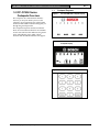
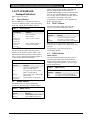
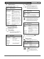
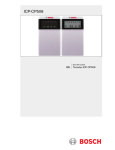
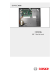
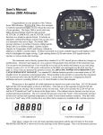
ICP-CP508
User's Guide
EN
ICP-CP508 Codepads
ICP-CP508 | User's Guide | 1.0 ICP-CP508 Series Codepads Overview
1.0 ICP-CP508 Series
Codepads Overview
1.1
EN | 2
Codepad Diagrams
Figure 1:
ICP-CP508W LED Codepad Display
Figure 2:
ICP-CP508LW Eight Zone LCD
Codepad Display
Figure 3:
Codepad Buttons
The codepad is the communications interface
between you and your alarm system. Use the
codepad to issue commands. The codepad offers
both visual and audible indications that guide you
through the general operation.
The codepad incorporates numerous indicators.
There are zone indicators that show the condition
of each zone and four other indicators for general
status. The following pages outline a list of
situations and the relevant indicators that appear.
Bosch Security Systems, Inc. | 9/08 | F01U089856-01
ICP-CP508 | User's Guide | 2.0 ICP-CP508W LED Codepad Indicators
2.0 ICP-CP508W LED
Codepad Indicators
Refer to Figure 1 on page 2.
2.1
Zone Indicators
The zone indicators (1 to 8) show the status of
each zone as defined in Table 1. The zones belong
to the area with the lit Area Display indicator.
Table 1:
Zone Indicators
When programming in Installer’s Programming
Mode or using a Master Code function, the
MAINS indicator lights to indicate a location value
from 10 to 15. The MAINS indicator represents
the tens digit, which is added to the value of the lit
zone indicator (for example, if the value
programmed in a location is 12, the MAINS and
Zone 2 indicators light).
2.4
FAULT indicator
The FAULT indicator lights when the system
detects a system fault as defined in Table 4.
Table 4:
Zone Indicator
On
Off
Flashing Fast
(0.25 sec on/
0.25 sec off)
Flashing Slow
(1 sec on/
1 sec off)
2.2
Definition
Zone is unsealed.
Zone is sealed.
Zone is in alarm condition.
Zone is manually isolated or
selected to be isolated.
STAY Indicator
The STAY indicator lights when the system is
armed in STAY Mode 1 or STAY Mode 2. The
STAY indicator flashes with the AWAY indicator
when you are in Installer’s Programming Mode or
you are using a Master Code function.
Table 2:
STAY Indicator
Indicator
On
Off
Flashing
Flashing once
every 3 sec
2.3
Definition
The system is armed in STAY
Mode 1 or STAY Mode 2.
The system is not armed in STAY
Mode 1 or STAY Mode 2.
Zone isolating mode or setting STAY
Mode 2 zones.
Day Alarm status on/off indicator
MAINS Indicator
The MAINS indicator displays whether the
system’s AC MAINS supply is normal or failed.
Table 3:
Indicator
On
Flashing
MAINS Indicator
Definition
The AC MAINS power is normal.
The AC MAINS supply failed.
Bosch Security Systems, Inc. | 9/08 | F01U089856-01
EN | 3
FAULT indicator
Indicator
On
Off
Flashing
Definition
A system fault must be corrected.
The system is normal (no faults).
A system fault must be acknowledged.
Each time a new system fault is detected (the
FAULT indicator flashes), the codepad beeps once
per min.
Press [AWAY] to stop the beeping and to
acknowledge the fault.
2.5
AWAY Indicator
AWAY Indicator
The AWAY indicator lights when the system is
armed in AWAY Mode. The AWAY indicator
flashes with the STAY indicator when you are in
Installer’s Programming Mode or you are using a
Master Code function.
Table 5:
Indicator
On
Off
AWAY Indicator
Definition
The system is armed in AWAY Mode.
The system is not armed in AWAY Mode.
ICP-CP508 | User's Guide | 3.0 ICP-CP508LW LCD Codepad Indicators
2.6
Audible Indicators
3.2
AWAY Indicator
The AWAY indicator appears when the
system is armed in AWAY Mode. The
AWAY indicator also flashes in unison with
the STAY indicator when programming
various options throughout this user’s guide.
The codepad provides a number of audible
indications as defined in Table 6.
Table 6:
Audible Indicators
Audible Indicator
One short beep
Two short beeps
Three short beeps
One long beep
One short beep
every sec
One short beep
every 2 sec
One short beep
every min
Definition
A button was pressed on the
codepad, or Exit Time ended when
arming in STAY Mode 1 or STAY
Mode 2.
The system accepted your code.
The system executed the requested
function.
Exit Time ended when arming in
AWAY Mode, or the requested
operation was denied or aborted.
Walk Test Mode is currently active,
or warning before automatic arming
takes place.
Telephone Monitor Mode is active.
There is a system fault to be
acknowledged.
3.0 ICP-CP508LW LCD
Codepad Indicators
Refer to Figure 2 on page 2.
3.1
Zone Indicators
1 2 3 …. The zone indicators (1 to 8) display the
status of the zones. Table 1 lists the various
situations that the indicators show.
Table 2:
AWAY Indicator
AWAY
Indicator
On
Off
Definition
3.3
STAY Indicator
Table 3:
Definition
Zone is unsealed.
Zone is sealed.
Zone is in alarm condition.
Definition
Off
Flashing twice
a sec
Flashing once
every 3 sec
System is armed in STAY Mode 1 or
STAY Mode 2.
System is not armed in STAY Mode 1
or STAY Mode 2.
Zone Isolating Mode or setting STAY
Mode 2 zones.
Day alarm status – day alarm turned
on.
System Disarmed
This indicator appears with the
when the system is disarmed.
3.5
indicator
MAINS Indicator
The MAINS indicator appears when the
system’s AC MAINS supply is normal or failed.
Table 4:
Zone is manually isolated or
selected to be isolated.
STAY Indicator
STAY
Indicator
On
Zone Indicator
Zone Indicator
On
Off
Flashing Fast
(0.25 sec on/
0.25 sec off)
Flashing Slow
(1 sec on/
1 sec off)
System is armed in AWAY Mode.
System is not armed in AWAY Mode.
The STAY indicator appears when the system
is armed in STAY Mode 1 or STAY Mode 2.
The STAY indicator also flashes in unison with
the AWAY indicator when programming
various options throughout this user’s guide.
3.4
Table 1 :
EN | 4
MAINS Indicator
MAINS Indicator
On
Flashing
3.6
Definition
AC MAINS power normal.
AC MAINS supply failed.
Off Indicator/Zone Sealed
The
indicator appears when the system
is disarmed and flashes when a zone
becomes unsealed when disarmed. The
indicator stops flashing when all zones are
sealed.
Bosch Security Systems, Inc. | 9/08 | F01U089856-01
ICP-CP508 | User's Guide | 4.0 Arming and Disarming
3.7
On Indicator/Zone In Alarm
indicator appears when the system
The
is armed and flashes when an alarm occurs.
The indicator resets after a valid User Code
is entered.
4.0 Arming and Disarming
4.1
Arming in AWAY Mode
When you leave your premises and require all
zones to be in a ready state to detect intrusion, you
arm the system in AWAY Mode. When returning
to your premises, disarm your system so that you
do not sound a false alarm.
EN | 5
4.4
Enter your code and press [STAY]. Two beeps
sound and the STAY indicator extinguishes. The
system is now disarmed.
5.0 User Codes
5.1 Adding a User Code
1.
There are two different methods for arming the
system in AWAY Mode. Method one is standard
and always operates. Method two is optional and
may be disabled by your installer if you do not
want to use single button arming.
2.
Arming in AWAY Mode, Method 1
3.
Enter your user code followed by the [#] key (for
example, [2 5 8 0 #]). Two beeps sound and the
AWAY indicator displays. Exit time starts
counting.
Arming in AWAY Mode, Method 2
Hold down the [#] key until two beeps sound.
The AWAY indicator appears and exit time starts
counting.
4.2
Disarming from AWAY Mode
Enter your user code followed by the [#] key (for
example, [2 5 8 0 #]). Two beeps sound.
4.3
Arming in STAY Mode
STAY Mode 1 is used when you need to arm the
perimeter and unused areas of the premises to
detect a would-be intruder entering the premises,
while at the same time being able to move freely
within an area that is automatically isolated.
STAY Mode 2 is used when you need to arm the
perimeter and unused areas of the premises to
detect a would-be intruder from entering the
premises, while at the same time being able to
move freely within an area that is automatically
isolated.
Arming in STAY Mode 1
Press and hold [STAY]. When two beeps sound,
release the button. The STAY indicator lights and
Exit Time starts.
Arming in STAY Mode 1
Press and hold [0].When two beeps sound, release
the button. The STAY indicator lights and the Exit
Time starts.
Bosch Security Systems, Inc. | 9/08 | F01U089856-01
Disarming from STAY Modes 1
and 2
Enter your four-character Master Code,
followed by [1] and [#] (for example,
[2 5 8 0 1 #]).
Three beeps sound and the STAY and AWAY
indicators flash.
Enter the user code number (1 to 8) followed
by the [#] key (for example, [2 #] = User 2, [8
#] = User 8). Two beeps sound and the
selected user number appears on the codepad
indicators.
Enter the digits required for the new code
followed by the [#] key (for example, for user
code 5768, enter [5 7 6 8 #]). Two beeps
sound and the STAY and AWAY indicators
turn dark.
To add or change other user codes, repeat this
procedure as many times as required.
5.2
Deleting a User Code
Enter your four-character Master Code, followed
by the [1] and [#] keys (for example, [2 5 8 0 1 #]).
Three beeps sound and the STAY and AWAY
indicators flash.
Enter the user code number (User Code 1 to 8,
Radio User Code 9 to 16), followed by the [#] key
(for example, [2 #] = User 2, [1 6 #] = User 16).
Two beeps sound and the selected user number
appears on the codepad indicators.
Press the [*] key to delete the selected user code.
Two beeps sound and the STAY and AWAY
indicators turn dark. To delete other user codes,
repeat this procedure as many times as required.
6.0 Isolating Zones
Isolating zones allow you to manually disable one
or more zones before arming the system. Once a
zone is isolated, you can access that zone during
the armed state without activating an alarm.
For example, you might need to isolate a zone
because before arming the system a PIR detector
might generate a false alarm, or you need to leave
a pet inside a particular zone while away.
Isolating zones is performed by one of two
methods. Method two is optional and allows only
those user codes programmed by your installer
access to isolate zones.
ICP-CP508 | User's Guide | 7.0 Panic Alarms
6.1
Standard Isolating: Method 1
Standard Isolating allows all users to isolate zones
without knowing a valid user code.
4. Press the [*] key twice to enter Isolating Mode.
Three beeps sound and the STAY indicator
flashes.
5. Enter the zone number (1 to 8), followed by
the [*] key (for example, [1 *] = Zone 1, [2 *]
= Zone 2).
Each zone to isolate has a corresponding zone
indicator that flashes.
6. If you select an incorrect zone to isolate, enter
the incorrect zone number again followed by
the [*] key.
7. Repeat Step 2 if you are isolating more than
one zone, until all zones to isolate are selected.
8. Press the [#] key after all selected zones are
isolated.
Two beeps sound and the system returns to the
disarmed state.
6.2
EN | 6
10.0 Initiating Entry Warning
Hold down the [1] key for 2 sec. The codepad will
start beeping to indicate the entry warning timer
has started. At the end of the entry warning delay
time (15 sec), Zone 1 will go into alarm and the
internal sounder will emit a siren sound.
Entering a valid user code during entry warning
time disarms the system.
11.0 Changing the Codepad
Buzzer Tone
Hold down the [8] key on the codepad. The tone
of the buzzer will start to increase in pitch. Release
the [8] button when the desired tone is reached.
12.0 Specifications
Table 5:
Specifications
Code-based Isolating: Method 2
Code-based isolating requires a valid user code to
isolate a zone.
1. Press the [*] key once.
2. Enter your user code and press [*].
3. Enter the zone number that you want isolated,
followed by the [*] key.
4. Repeat Step 2 if more than one zone is
required to be isolated.
5. Press the [#] key after all selected zones are
isolated.
7.0 Panic Alarms
An audible alarm activates when the [1] and [3]
keys or the [*] and [#] keys are pressed
simultaneously. Contact your installer to disable
the ability to activate the codepad panic alarm or
to silence the codepad panic alarm.
8.0 Fire Alarms
An audible codepad Fire Alarm activates when
you press [4] and [6] on the remote codepad
simultaneously. A distinct fire sound emits through
the horn speaker to indicate this type of alarm.
Contact your installer to disable the ability to
activate the codepad panic alarm or to silence the
codepad fire alarm.
9.0 Medical Alarms
An audible codepad Medical Alarm activates
when you press [7] and [9] simultaneously.
Contact your installer to disable the ability to
activate the codepad panic alarm or to silence the
codepad medical alarm.
Bosch Security Systems, Inc. | 9/08 | F01U089856-01
Temperature Range
Humidity
Operating Voltage
Current Draw
RF Immunity (RFI)
0oC to +50 oC
o
o
(+32 F to +122 F)
20% to 90% (non-condensing)
11 VDC to 14VDC
50 mA (max)
Complies with AS/NZS3548
ICP-CP508 | User's Guide | Notes
EN | 7
Notes
Bosch Security Systems, Inc. | 9/08 | F01U089856-01
© 2008 Bosch Security Systems, Inc.
F01U089856-01