1
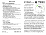
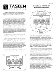
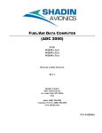
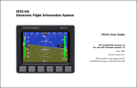
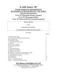
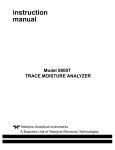
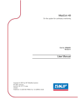
2002.01.06
User's Manual
Series 2000 Altimeter
Congratulations on your purchase of the Taskem
Series 2000 altimeter. P L E A S E ! take a few moments
to read this manual thoroughly so you will get the most out
of your purchase. The Series 2000 is an all solid state,
highly advanced design which provides accurate
ALTITUDE, CLIMB RATE, and ALTITUDE ALERT
functions in a simple-to-operate format. It includes an
adjustable, calibrated Kollsman window that can also serve
as a barometer when not in flight. The Model 2000
pressure reference is in inches of mercury (inHg) and the
Model 2001 is in millibars (mBar). Options include
Outside Air Temperature (OAT) and Density Altitude in
addition to a Mode C encoder output. All data is presented on an easily readable liquid crystal display (LCD)
which is backlighted for night viewing. Light emitting diodes (LED) and custom LCD legends alert the
operator to various modes and warnings.
The instrument can be directly operated from standard 14 or 28V aircraft power without any changes or
modifications. All power and outputs are via a connector that protrudes from the back of the instrument case.
You can power the instrument now if you would like to try each of the modes and features as you read along.
Connect a source of 11 to 35 VDC power with positive to the RED wire and negative to BLACK (see Fig 2,
page 5). These wires are protected for polarity reversal, but APPLYING POWER TO OTHER PINS CAN
CAUSE PERMANENT DAMAGE! Two standard 9V alkaline batteries provide a convenient source of 18V
portable power for operation on the kitchen table. When installed in the aircraft it is typical that the instrument
will be powered only when the MASTER switch is on. Current drain is quite low, averaging less than 80
milliamps and never exceeding 360mA, so a 1A circuit breaker is more than adequate.
When power is first applied, all visible indicators are turned on in order to test them. All 4 LEDs should
light and the LCD should appear as shown at left below. Note that one of the segments in both the left and
rightmost digits are missing - this is normal, as they are not used. After a few seconds, the LEDs will go out
and the LCD should read "cold" as shown in the figure below. This indicates that an internal oven has not yet
reached operating temperature. The oven contains the pressure sensor (the "heart" of the instrument) and must
be held at an elevated and regulated temperature to isolate it from normal ambient variations. Note that while
the oven is "cold", none of the switches have any effect and no outputs are available at the external connector.
LCD segment test
oven below temperature
After about 1 minute, the oven will reach operating temperature and the unit will enter its first mode,
PRESSURE REFERENCE shown at left in the drawings on the following page. This is the barometric pressure
−1−
reference currently being used to determine altitude. The LCD legend "PRESSURE" will illuminate to indicate
this, and the value will be set to the last-used pressure reference. Pushing the UP/DN switch can then change
the reference. Each momentary operation of this spring loaded switch will change the display by 0.01 inHg (or
1 mBar), while pushing and holding the switch in either position will change the readings rapidly.
Momentarily press the MODE switch once and the instrument will enter its second mode, ALTITUDE
as indicated by the LCD legend in the center drawing. At this point you may see some small variations in the
displayed altitude until the oven temperature stabilizes. It takes less than a minute for the oven to reach
operating temperature, but several minutes more for it to stabilize and give fully accurate readings. Oven
warm-up details are provided in a separate paragraph. Using the UP/DN switch, change the displayed altitude.
What you're actually doing is changing the barometric pressure reference again, but this time while looking at
its effect on computed altitude. If you know your current elevation, set the displayed altitude to that value.
PRESSURE REF
1st mode
ALTITUDE
2nd mode
CLIMB RATE
3rd mode
Now momentarily press the MODE switch once more to enter the CLIMB RATE mode. The display
should read zero, but as before if the oven temperature hasn't yet stabilized, you could get non-zero readings
until the oven settles. The climb rate is displayed in increments of 50 feet/minute. Note that the UP/DN switch
has no effect in this mode, and this will be the case in any other situation where it doesn't apply. Press the
MODE switch once more and the instrument returns to the PRESSURE REFERENCE mode. If you did set the
altimeter to your known altitude, the instrument now indicates the current barometric pressure (at sea level) just
as a standard barometer does. These are the three main modes, and the instrument continuously cycles through
each as the MODE switch is pressed. Other modes and how to get to them are described next.
Figure 1 on the following page shows how the instrument is sequenced from one mode to the next. It's
called a flow chart and may look complicated at first, but it's not. It's really very simple to understand and once
you learn the reasoning behind it, is easy to remember too. The names of each mode are contained within the
oval shapes, and arrows connecting the different modes represent the action of pressing the MODE switch. If
the arrow is not labeled it's a normal, momentary press of the switch. On the other hand, if the arrow is labeled
"2S", this means that the MODE switch is pushed (and not released) for 2 seconds. After 2 seconds, the LCD
will go off (indicating that the switch has been held long enough) and when released, the instrument enters the
new mode.
Note that each mode can have several arrows leading into it, but at most only two leading out, 2S and
momentary. Also note what we refer to as the "main loop". This is the sequence PRESSURE - ALTITUDE CLIMB and back again as was described earlier. Each of the arrows involved in this loop has no label meaning
a momentary press of the MODE switch. Each of the modes on the main loop has some auxiliary modes that
can be invoked by pressing the MODE switch for 2 seconds. The auxiliary modes have been arranged so that
they have some logical connection to the main loop mode from which they are accessed.
Take for instance, the PRESSURE ALTITUDE mode. (A brief tutorial on the concepts of pressure and
density altitude appears at the back of this manual.) Since pressure altitude is related to the barometric pressure
reference, it is linked to and accessed from the PRESSURE REF mode. From the PRESSURE REF mode,
press and hold the MODE switch for 2 seconds. When the LCD blanks, release the switch and you will see the
−2−
Figure 1 - MODE FLOW CHART
PRESSURE ALTITUDE displayed as indicated by that LCD legend and shown at left in the set of figures at the
bottom of the page. We could also have determined pressure altitude by first setting the PRESSURE reference
to standard pressure (29.92 for the Model 2000 and 1013 for the Model 2001) then read the ALTITUDE. The
PRESSURE ALTITUDE mode does this automatically and doesn't require us to alter the current reference and
possibly forget what it was. Press the MODE switch to return to the PRESSURE REF mode.
The next modes to be discussed are Outside Air Temperature (OAT) and DENSITY ALTITUDE. Since
these both directly affect aircraft climb rate, they are accessed from the CLIMB RATE mode. These modes are
an option and if not installed (or if a functional temperature sensor is not properly connected) the LCD will
indicate "off", meaning that the readings are off scale. From the CLIMB RATE mode, press and hold the
MODE switch for 2 seconds to enter the OAT mode. The LCD will appear as in the center illustration. Note
that there is no LCD legend that uniquely identifies the OAT mode. Rather, it is implied by the lower case "c"
to the right of the digits, indicating that the temperature is in °C. (There is no provision for readings in °F.)
Momentarily press the MODE switch and the mode will change to DENSITY ALTITUDE. Also note by
observing the flow chart, that repeatedly pressing the MODE switch will toggle between DENSITY
ALTITUDE and OAT. To return to the CLIMB RATE mode, press and hold the MODE switch while in either
OAT or DENSITY ALTITUDE.
PRESSURE
ALTITUDE mode
OAT mode
DENSITY
ALTITUDE mode
Next are the altitude ALERT modes and since they are concerned with maintaining a nearly constant
altitude, are accessed from the ALTITUDE mode. Press and hold the MODE switch to enter the ALERT SET
−3−
mode. The instrument should appear as shown at left in the next set of figures. Note that the green ALERT
LED is on and the "altitude" legend and value "200" appears on the LCD.
ALERT SET
mode
ALERT ALTITUDE
mode
ALERT DELTA
mode
The ALERT SET mode establishes the TARGET altitude and the deviation above or below that altitude
that will be allowed. On entering this mode the current altitude, rounded to the nearest 100 feet, is established
as the TARGET. Thus, if the altitude just prior to entering the ALERT SET mode was 5230 feet, the TARGET
would be set to 5200. Likewise, an altitude of 8660 would result in a TARGET of 8700 (portrayed above). The
TARGET value is not adjustable and can only be set as just described. You must climb or descend to within 50
feet of the desired altitude, THEN enter the ALERT SET mode to set it properly.
The "200" in the display indicates that an allowable WINDOW of ±200 feet around the TARGET
altitude is in effect. This is a default value and can be changed from within this mode in 50' increments using
the UP/DN switch. As depicted in the flow chart, the ALERT SET mode is accessed only upon first entering
the ALERT modes. Thus, once you move on to the ALERT ALTITUDE mode, the only way to change the
WINDOW is to exit the ALERT modes and start again.
Once the desired WINDOW has been set, momentarily press the MODE switch to enter the ALERT
ALTITUDE mode. The only readily apparent difference between this mode and the normal ALTITUDE mode
is that one of the ALERT LEDs will be on. Altitude is displayed just as in the normal ALTITUDE mode, but it
is also being constantly monitored and compared to the TARGET altitude and WINDOW. Press the MODE
switch again, to enter the ALERT DELTA mode. Here, the deviation above or below the TARGET altitude is
displayed rather than absolute altitude. This format makes it very easy to maintain a fixed altitude by simply
holding a zero reading. Negative values indicate that you are below TARGET, positive above.
Repeatedly pressing the MODE switch toggles back and forth between ALERT DELTA and ALERT
ALTITUDE. There is no difference in the LCD legends or LEDs, and the only clue as to which mode you are
actually in is the numeric values. There is generally no confusion since the ALERT DELTA mode will usually
have small and sometimes negative numbers while ALERT ALTITUDE will have much larger positive
numbers equal to your current altitude. There could be some confusion if trying to use the ALERT modes at
very low altitudes where the DELTA and ALTITUDE would be comparable.
If altitude approaches or exceeds the established WINDOW, both audible and visual warnings are
generated. The audio output can not drive a loudspeaker directly, but must be wired into the accessory input of
an intercom system. It incorporates a built-in volume control to set the level. Audio is incorporated into all
instruments. Its use is optional as the visual indicators provide complete information. The visuals are by means
of the green, yellow and red ALERT LEDs. If altitude is within ±70% of the selected WINDOW, the green
LED remains on continuously and no audio warning is produced. For instance, if the selected WINDOW was
the default 200 feet, no warnings would be produced if within ±140 feet of the TARGET. Likewise, if the
WINDOW were set to 500 feet, no warnings would be generated if within ±350 feet of TARGET.
If you exceed 70% of the WINDOW, the yellow LED flashes and if audio is connected, a beeping
warning tone is also heard. A high pitched tone indicates you are above target, while a low frequency means
you are below. The audio tone is silenced by momentarily pushing the MODE switch, but the yellow LED will
continue to flash. The yellow LED will stop flashing once the altitude is returned to within 70% of WINDOW,
−4−
and the audio warning will also stop (if not already silenced manually).
In a like manner if you exceed 100% of the WINDOW, the red LED flashes and the audio warning tone
sounds (even if it had been silenced after crossing the 70% threshold). The sound is the same as there is no
audio distinction between the 70 and 100% thresholds. The ALERT LED will return to flashing yellow if the
altitude is adjusted to less than 100% of WINDOW and will go back to solid green once within 70%. If the
audio had not been manually silenced, it will also automatically stop at this point, but it is more typical to do it
manually to prevent it from masking audio communications.
Pressing and holding the MODE switch from any of the ALERT modes returns the instrument to the
regular ALTITUDE mode, as shown in the flow chart.
While in any of the operating modes, the OXYGEN LED will illuminate continuously if altitude
exceeds 12,500 feet to warn that oxygen is required.
ELECTRICAL CONNECTIONS
Gold plated pins protrude from the back of the case and all electrical connections are through this plug.
Odd numbered pins are on the bottom and even on top (see Fig 2). A termination board with mating connector
is supplied with all units and is oriented as shown then pushed on until fully seated. This provides a handy
method to strain relieve all wires. It is supplied with wires for DC power and backlighting and others must be
added as needed. Solder pads are numbered identical to connector pins but are not in order.
Pins are grouped by functions. 1 through 10 applies to all instruments and involves backlighting, DC
power, serial data and audio outputs. Pins 11, 12 & 13 are for the temperature sensor and function only if that
−5−
option is installed. The remaining pins 14 through 26 all support the Mode C encoder option. Table 1 lists the
use of each connector pin and functional descriptions of each follows.
TABLE 1 − CONNECTOR FUNCTIONS
Pin
1
2
3
4
5
6
7
8
9
10
11
12
13
Function
+28V backlighting
+14V backlighting
GROUND
DC power (+11 to +35V)
Not used
Not used
audio shield
audio signal
serial data ground
serial data
temp probe shield
temp probe red
temp probe black
Pin
14
15
16
17
18
19
20
21
22
23
24
25
26
Function
ground
STROBE
ENABLE
C2
C1
B4
B2
B1
A4
A2
A1
C4
ground
M
O
D
E
C
BACKLIGHTING: Pin 1 or 2 is used for illumination of the LCD for night viewing (+14VDC to pin 2 or
+28VDC to pin 1). The wire supplied is pre-wired to pin 2 since 14V is typical. The wire must be unsoldered
and connected to pin 1 for operation from +28V. Do not apply power to both pins at the same time. A small,
20KΩ rheostat can be connected in series for brightness control.
DC POWER: DC power to operate the instrument is applied to pins 3 and 4. Pin 3 is GROUND and connects
to the negative terminal. Connect pin 4 to positive in the range of 11 to 35 volts. Note that all ground and
shield pins (3, 7, 9, 11, 14 & 26) are internally tied together.
AUDIO: Connect shielded wire to auxiliary audio intercom input as listed above.
SERIAL DATA: Serial data is available at pin 10. Use twisted pair to minimize capacitance. Connect the
twisted pair return wire to pin 9.
TEMPERATURE PROBE: If this option is installed, connect probe wires as listed above. See instructions
supplied with OAT/density altitude option.
MODE C: All Mode C connections are via pins 14 through 26. Refer to detailed instructions supplied with the
Mode C option.
SERIAL DATA
The serial data output provides the means to send all Series 2000 data to other instruments and systems.
Typical of these are autopilots, recorders, flight computers and any other device that can make use of altitude,
pressure altitude, density altitude, OAT or climb rate information. For instance, an air speed indicator may
make use of this data to compute true airspeed. Without this information, it would only be capable of
displaying indicated airspeed.
−6−
The following paragraphs describe the data structure and format. The description is very detailed and
assumes a working knowledge of electronics and computers. The average user will typically have no interest in
this and is encouraged to skip this section.
The data rate is fixed at 9600 baud with one stop bit, 8 data bits and no parity. A field of 9 bytes
containing all data is output every 0.6 seconds with no handshaking. Although the data structure conforms to
the RS-232 format, the logic levels do not. Outputs levels are 5V CMOS with an added 10KΩ series resistance.
As such, it can not drive long cables, and load capacitance should be kept under 2000pF. If true RS-232 levels
are required, Maxim Corp. or Linear Technology offer several 5V to RS-232 level converters which can be
operated from a single power supply.
The data format is shown in Figure 3. All values are in two's compliment, signed binary. Altitude,
pressure altitude and density altitude are encoded in 16 bits with 1 LSB = 1 foot. For example, 1AD8h = 6,872
feet and FCC5h = −827 feet. Although displayed values are rounded to the nearest 10 feet (100 for density
altitude), serial data is not. This is not to say that serial data has a 1 foot resolution. It will typically change in
increments of 5 feet or more depending on altitude.
Outside air temperature is 8 bits with 1 LSB equal to 1°C. Examples are 1Eh = 30°C and E3h = −29°C.
If the temperature/density altitude option is not installed or a temperature sensor is not properly connected, this
byte will contain 80h (−128°C). This highly improbable, yet easily detectable value is used to indicate an "off
scale" condition. Under the same conditions, the two density altitude bytes will contain 8000h (−32,768 feet).
Climb rate is encoded in 16 bits with 1 LSB equal to 1 foot/minute. As with altitude, displayed values
are rounded but serial data is not.
PRESSURE AND DENSITY ALTITUDE
This section is intended to explain the concepts of pressure and density altitude for novices or those
veteran flyers that need a clearer understanding than they currently have.
Many critical aircraft performance parameters are highly dependent on the density and atmospheric
pressure of the air in which the aircraft is enveloped. One might think that these are related only to altitude, and
−7−
therefore knowing the altitude will tell the whole story, but this is not the case. At any given altitude, pressure
and density will vary from day to day and even hour to hour.
In order to get around this problem, experts studied the atmosphere and developed what is called a
"standard day". This is simply a tabulation of the AVERAGE pressure, density and temperature versus altitude
taken over many years of measurements.
Using this "standard day" we can refer to any air density or pressure indirectly in terms of an equivalent
altitude. For instance, instead of saying that the current atmospheric pressure is 22.225 inches mercury, we can
say that the pressure is the same as that experienced at 8000 feet on a standard day. Stated more simply, we say
that the PRESSURE ALTITUDE is 8000 feet. In a like manner, instead of saying that the current air density is
0.00167 slugs per cubic foot (these are proper units!) we say that the density is the same as that experienced at
11,500 feet on a standard day. In simpler words, the DENSITY ALTITUDE is 11,500 feet.
Let's summarize it from a slightly different viewpoint. Pressure altitude IS NOT AN ALTITUDE, it's a
pressure. When we say that the pressure altitude is 5000 feet, what we're really saying is that the pressure is the
same as that normally experienced at 5000 feet on a standard day. Density altitude is not an altitude either, it's
an air density. If we say that the density altitude is 6500 feet, we're saying that the air density is the same as
what would normally be experienced at 6500 feet.
How do we determine pressure and density altitude? For pressure altitude, all that is required is to know
the pressure at sea level on a standard day, which is 29.92 inHg or 1013 mBar. If we enter this value as the
barometric reference for the altimeter, we are basically fooling the instrument into thinking it's a standard day.
The altimeter then indicates pressure altitude. Density altitude is more involved. It is related to temperature
and pressure altitude by a very complex formula. The usual approach is to use a chart or slide rule such as the
E6B flight computer or its electronic equivalents. The inputs in each case are pressure altitude and temperature.
Aircraft performance parameters such as climb rate, take off distance and maximum take off weight are
all very dependent on air density. For this reason, performance curves published in the Flight Manual for each
aircraft are given in terms of density altitude (or pressure altitude and temperature).
OVEN WARM-UP
As mentioned previously, the pressure sensor is the heart of the system and must be held at a controlled
and elevated temperature to achieve the required system accuracy. As such, it is housed in a precisely regulated
oven and needs sufficient time to reach uniform operating temperature.
After the "cold" LCD warning first disappears, the displayed and reported altitudes are typically about
100 feet low, well within the FAA specification of ±125 feet for MODE C encoders. After 20-30 minutes, this
error diminishes and approaches zero.
This behavior is due to the fact that we started out with a cold oven. Although the oven indicates that
it's at operating temperature, the pressure sensor takes much longer to reach temperature and fully stabilize. It's
like putting a turkey in a cold oven, then turning the oven up to 400°F. After only a few minutes, the oven will
indicate that it's at 400°, but the turkey will take hours before it is uniformly heated to that temperature. The
sensor lag time isn't as extreme as this example, but the concept is the same.
This performance is typical of "blind" MODE C encoders and we don't object to this initial error
because we usually aren't even aware of it. In the case of an altimeter with a display however, the discrepancy
becomes obvious and we are led to believe that the unit is out of calibration - it's not.
−8−
We're used to mechanical altimeters which require no warm-up and give their rated accuracy at all
times. If we are sitting at an airport that has a known elevation of 200' and we set the altimeter to the current
barometric pressure, the altitude usually reads exactly 200'. If it doesn't we pull the set knob out and calibrate it.
In the case of the electronic altimeter, this initial discrepancy between altitude and pressure are not an indication
that it is out of calibration. We just have to allow sufficient time for the difference to diminish to insignificance.
Assuming we initially set the barometric reference correctly, typical warm-up characteristics for the
Series 2000 are as follows. A couple of minutes after first powering it from a cold start, displayed altitudes will
typically indicate about 100 feet lower than true. This initial difference will then gradually diminish over a
period of about 30 minutes.
As a result of this behavior, the following operating procedure is suggested. During normal runup, set
the altimeter to the known airport ELEVATION, NOT the known BAROMETRIC PRESSURE. This will
then give the greatest displayed accuracy, while leaving the pattern and potentially clearing local obstacles
while climbing to intended altitude. After 15 minutes or more, the greatest accuracy in displayed altitude will
then be obtained by setting the baro as reported by Air Traffic Control or an ATIS tape.
REMEMBER - The MODE C altitudes reported by this instrument are not affected by the barometric
reference setting, and are always within the FAA designated specifications. The above procedures only affect
altitudes displayed on the LCD and are intended to explain and correct for an initial −100' offset.
Many electronic instruments utilize ovens to achieve high accuracy. To avoid warm-up delays, some of
them simply leave their ovens powered at all times, even when the instrument is not in use. Unfortunately this
is not practical using typical 12V aircraft battery power. Once warm, the Series 2000 consumes only about 1
watt. Even at this low rate, it would consume 50% of the capacity of a typical 20 to 25 amp-hour aircraft
battery in only 5 days.
MECHANICAL CONSIDERATIONS
The instrument is ruggedly built and can withstand severe vibration, but no device can be made totally
vibration proof. Mount the instrument securely. This is particularly important for installations in aircraft
powered by two stroke engines as is common with ultralights.
WARRANTY
This instrument is warranted against defects in materials and workmanship for a period of two years
from the date of purchase. As such, we will repair or replace (at our option) any unit found to be defective
within this period. You must file the warranty registration card with us when purchased (preferred) or show
proof of purchase with a dated, itemized receipt from a recognized aviation retailer. Beyond the warranty
period, we repair and calibrate instruments promptly, and for very reasonable cost.
CALIBRATION
This section outlines the steps required to properly calibrate the Series 2000 altimeter. Two different
procedures (BARO SET and FULL CALIBRATION) are listed and vary considerably in complexity and
equipment required.
−9−
The BARO SET procedure is comparable to pulling out the set knob on a standard mechanical altimeter
and adjusting so that the baro and altitude scales read correctly at a known, fixed (airport) altitude. This
requires no special equipment other than radio access of the current local barometric pressure. It is easily done
by the end-user without having to open the instrument.
The FULL CALIBRATION procedure is considerably more involved. It requires specialized equipment
and should only be done by qualified service personnel.
BARO SET
1. Allow the instrument to warm up for ONE HALF HOUR ----- THIS IS EXTREMELY IMPORTANT! A
full and thorough warm up is required for proper adjustment.
2. Obtain the current sea level barometric pressure from a reliable source (ATC tower, ATIS, ASOS, etc.).
Note that ATIS tapes are typically updated at 45 minutes after the hour and diminish in accuracy as they
age. ASOS data (where available) is updated every minute and is always current, as is the ATC tower.
3. Set the instrument to the PRESSURE mode. Using the UP/DN switch set the reference to the current sea
level barometric pressure.
4. Set the instrument to the ALTITUDE mode. Using a suitably sized straight blade screwdriver, adjust the
OFFSET potentiometer until the altimeter displays the known airport elevation. The adjustment is
accessible through the front panel left of the alert LEDs. Wait one minute and readjust if necessary.
NOTE: Be wary of airports that are not level. Published airport elevations reflect the runway altitude at the
control tower or runway center. If your altitude during this adjustment differs considerably from the airport
reference, your altimeter will be off by the same amount. If a significant grade exists, you should first relocate
closer to, and level with, the tower.
FULL CALIBRATION This can be performed using either a pressure STANDARD (displays pressure in
inHg or mBar) or a STANDARD altimeter (displays altitude in feet). Follow the procedure that applies to the
STANDARD available. The diagram on the following page shows the location of the various adjustments.
Using pressure STANDARD:
Equipment required:
a). Pressure STANDARD capable of displaying absolute pressure in inHg and accurate to 0.02 inHg over a
range of 8.0 to 31.0 inHg, or comparable units if using mBar model.
b). Hand operated vacuum pump (if not built into pressure STANDARD).
c). 14VDC power source capable of 400 mA.
1. Shut off power and remove the interface circuit board connector from the back of the instrument. At back
of instrument, disconnect static port plastic tubing.
2. Using a #1 Philips screwdriver, carefully remove the two screws from the front face. Push on the circuit
board extending from the back of the case then remove the electronics assembly.
− 10 −
3. Connect tubing from STANDARD to pressure port on back of altimeter using plastic tubing and size
adapters as required.
4. If vacuum pump is separate item,
connect to vacuum circuit using a
tee.
5. Connect the interface circuit board
(or other suitably powered
connector) to the altimeter.
6. Apply DC power while pressing
(and holding) the MODE switch in.
Release MODE switch when
altimeter LEDs go off.
Some components are omitted for clarity.
Others may only be present with options.
NOTE: The above action places the altimeter in its ABSOLUTE PRESSURE mode and is used for calibration
purposes. If the MODE switch is inadvertently pressed afterwards, power will have to be removed and the
above repeated to invoke the ABSOLUTE PRESSURE mode again.
7. Verify that the altimeter initially displays "cold" then after about one minute enters the ABSOLUTE
PRESSURE mode. This is indicated by the PRESSURE legend on the LCD and the fact that the UP/DN
switch has no effect.
8. Allow the instrument to warm up for ONE HALF HOUR ----- THIS IS EXTREMELY IMPORTANT! A
full and thorough warm up is required for proper adjustment.
9. Pump the vacuum to about 11 inHg (absolute). Wait for altimeter reading to stabilize then adjust the
OFFSET potentiometer until the altimeter and STANDARD read the same.
10. Release the vacuum and wait for altimeter reading to stabilize. Adjust GAIN potentiometer until the
altimeter and STANDARD read the same.
11. The two previous adjustments are interactive. Repeat as necessary until both require no further adjustment.
12. Press the MODE switch once to enter the PRESSURE REFERENCE mode.
13. Disconnect vacuum tubing then verify pressure reference setting by performing BARO SET steps 2 through
4 and adjust if necessary.
14. This completes the calibration. Paint the GAIN potentiometer screw with RED paint or nail polish. Shut
off DC power and disconnect the interface circuit board connector. Install the electronics assembly back
into the case and secure with Philips screws. Be sure that the board is properly seated in the card slots on
either side of the case.
− 11 −
Using STANDARD altimeter:
Equipment required:
a). STANDARD altimeter capable of displaying altitude in feet and accurate to 20 feet over a range of
−1,000 to +30,000 feet.
b). Hand operated vacuum pump (if not built into STANDARD altimeter).
c). 14VDC power source capable of 400 mA.
1. Shut off power and remove the interface circuit board connector from the back of the instrument.
2. At back of instrument, disconnect static port plastic tubing.
3. Using a #1 Philips screwdriver, carefully remove the two screws from the front face. Push on the circuit
board extending from the back of the case then remove the electronics assembly.
4. Connect tubing from STANDARD to pressure port on back of altimeter using plastic tubing and size
adapters as required.
5. If vacuum pump is separate item, connect to vacuum circuit using a tee.
6. Connect the interface circuit board (or other suitably powered connector) to the altimeter.
7. Apply DC power and verify that the altimeter initially displays "cold" then after about one minute enters
the PRESSURE REFERENCE mode. This is indicated by the PRESSURE legend on the LCD and a
numeric display of 29.92 or 1013 depending on model.
8. Allow the instrument to warm up for ONE HALF HOUR ----- THIS IS EXTREMELY IMPORTANT! A
full and thorough warm up is required for proper adjustment.
9. Obtain the current sea level barometric pressure from a reliable source (ATC tower, ATIS, ASOS, etc.).
Note that ATIS tapes are typically updated at 45 minutes after the hour and diminish in accuracy as they
age. ASOS data (where available) is updated every minute and is always current, as is the ATC tower.
10. Set the STANDARD altimeter to the pressure reference obtained in previous step. Also, using the UP/DN
switch set the altimeter under test to the same reference.
11. Using the MODE switch, advance the altimeter under test to ALTITUDE mode.
12. Pump the vacuum to read about 25,000 feet on the REFERENCE altimeter. Wait for readings to stabilize
then adjust the OFFSET potentiometer until the altimeter under test and the STANDARD read the same.
13. Release the vacuum and wait for readings to stabilize. Adjust GAIN potentiometer until the altimeter and
STANDARD read the same.
14. The two previous adjustments are interactive. Repeat as necessary until both require no further adjustment.
15. This completes the calibration. Paint the GAIN potentiometer screw with RED paint or nail polish. Shut
off DC power and disconnect the interface circuit board connector. Install the electronics assembly back
into the case and secure with Philips screws. Be sure that the board is properly seated in the card slots on
either side of the case.
− 12 −