1
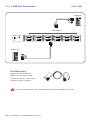
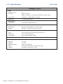
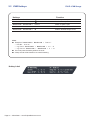
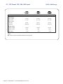
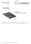
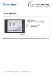
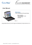
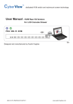
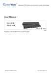
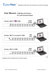
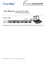
User Manual - Integrated DVI-D KVM
for LCD Console Drawer
DVI-D KVM
12-DVI
Rear
Designed/Manufactured by Austin Hughes and Distributed by Eclipse Rackmount, Inc.
Manual ML45V02A -- Generation 4 -- www.EclipseRackmount.com
Legal Information
First English printing, October 2002
Information in this document has been carefully checked for accuracy; however, no guarantee is given to the correctness
of the contents. The information in this document is subject to change without notice. We are not liable for any injury or
loss that results from the use of this equipment.
Safety Instructions
Please read all of these instructions carefully before you use the device. Save this manual for
future reference.
■
■
■
■
■
■
■
■
■
■
■
Unplug equipment before cleaning. Don’t use liquid or spray detergent; use a moist cloth.
Keep equipment away from excessive humidity and heat. Preferably, keep it in an air-conditioned environment with
temperatures not exceeding 40º Celsius (104º Fahrenheit).
When installing, place the equipment on a sturdy, level surface to prevent it from accidentally falling and causing
damage to other equipment or injury to persons nearby.
When the equipment is in an open position, do not cover, block or in any way obstruct the gap between it and the
power supply. Proper air convection is necessary to keep it from overheating.
Arrange the equipment’s power cord in such a way that others won’t trip or fall over it.
If you are using a power cord that didn’t ship with the equipment, ensure that it is rated for the voltage and current
labeled on the equipment’s electrical ratings label. The voltage rating on the cord should be higher than the one listed
on the equipment’s ratings label.
Observe all precautions and warnings attached to the equipment.
If you don’t intend on using the equipment for a long time, disconnect it from the power outlet to prevent being
damaged by transient over-voltage.
Keep all liquids away from the equipment to minimize the risk of accidental spillage. Liquid spilled on to the power
supply or on other hardware may cause damage, f re or electrical shock.
Only qualif ed service personnel should open the chassis. Opening it yourself could damage the equipment and
invalidate its warranty.
If any part of the equipment becomes damaged or stops functioning, have it checked by qualif ed service personnel.
What the warranty does not cover
■
■
■
Any product, on which the serial number has been defaced, modif ed or removed.
Damage, deterioration or malfunction resulting from:
Accident, misuse, neglect, f re, water, lightning, or other acts of nature, unauthorized product modif cation, or
failure to follow instructions supplied with the product.
Repair or attempted repair by anyone not authorized by us.
Any damage of the product due to shipment.
Removal or installation of the product.
Causes external to the product, such as electric power f uctuation or failure.
Use of supplies or parts not meeting our specif cations.
Normal wear and tear.
Any other causes which does not relate to a product defect.
Removal, installation, and set-up service charges.
□
□
□
□
□
□
□
□
Regulatory Notices Federal Communications Commission (FCC)
This equipment has been tested and found to comply with the limits for a Class B digital device, pursuant to Part 15 of
the FCC rules. These limits are designed to provide reasonable protection against harmful interference in a residential
installation.
Any changes or modif cations made to this equipment may void the user’s authority to operate this equipment. This
equipment generates, uses, and can radiate radio frequency energy and, if not installed and used in accordance with the
instructions, may cause harmful interference to radio communications.
However, there is no guarantee that interference will not occur in a particular installation. If this equipment does cause
harmful interference to radio or television reception, which can be determined by turning the equipment off and on, the
user is encouraged to try to correct the interference by one or more of the following measures:
■ Re-position or relocate the receiving antenna.
■ Increase the separation between the equipment and receiver.
■ Connect the equipment into an outlet on a circuit different from that to which the receiver is connected.
Page 02 -- ML45V02A -- www.EclipseRackmount.com
Contents
< Part 1 > DVI-D KVM Kit
12-DVI
1.1
KVM Port Connections
P.4
1.2
Specifications
P.5
< Part 2 > Using the KVM
2.1
KVM Buttons
P.6
2.2
KVM Hotkeys
P.7
2.3
DC Power: 12V, 24V, 48V Input
P.8
Page 03 -- ML45V02A -- www.EclipseRackmount.com
< 1.1 > KVM Port Connections
DVI-D KVM
USB Servers
DVI-D KVM port
Power
Audio
12
11
10
9
8
7
6
5
4
3
2
1
USB Servers
DVI KVM Cabling
CAI-6: 6 feet DVI KVM cable
CAI-15: 15 feet DVI KVM cable
( Server end: DVI-D + USB + Audio )
( KVM port: DVI-D + USB3.0 )
IP console, remote console, daisy-chain and OSD menu are not available for this model.
Page 04 -- ML45V02A -- www.EclipseRackmount.com
< 1.2 > Specifications
DVI-D KVM
Ending in 12-DVI
▀
KVM
Number of ports:
12
Connector:
DVI-D connector
USB 3.0 connector ( combined for keyboard, mouse & audio )
Connectivity:
Combo 4-in-1, KVM cable, 6 or 15 feet
▀
Audio Out
1 x 3.5mm stereo audio
▀
Management
PC Selection:
▀
▀
Front button & keyboard hotkey
Compatibility
Multi-platform:
Mix PCs, SUN and Mac G3 / G4 Mac / iMac
Support:
Windows 7 / Vista / 2003 / XP, Linux, Unix
Power
Input:
100 or 240V AC at 50 or 60 Hz via IEC type cord
Option DC:
12V / 24V / 48V DC input
Consumption:
Max. 48 Watt, Standby 5 Watt
▀
Regulatory Approval:
FCC, CE, RoHS
▀
Environmental
Operating:
0 to 50°C
Storage:
-5 to 60°C
Relative humidity:
90%, non-condensing
Shock:
50G peak acceleration (11ms, half-sine wave)
Vibration:
58~100Hz / 0.98G (11ms / cycle)
Page 05 -- ML45V02A -- www.EclipseRackmount.com
Part 2. Usage
DVI-D KVM Usage
2.1 KVM Buttons
Power ON
■ Turn off all servers and KVM switches
■ Make sure all cables / connectors are properly connected
■ Recommend Power ON sequence is monitor, KVM switch and finally the computer
Front Panel - Port LED Indications
DVI-D KVM 12 ports
PC port LEDs
PC port LEDs
Channel
button
Online : Blue LED on indicating a PC is connecting to the port
Active : Green LED on indicating a selected channel
Channel button
Button B is
non-functional
Press to select channel from 01 to 12
Page 06 -- ML45V02A -- www.EclipseRackmount.com
2.2 KVM Hotkeys
DVI-D KVM Usage
Hotkeys
Function
Scroll Lock + Scroll Lock +
Switch to previous port
Scroll Lock + Scroll Lock +
Switch to next port
Scroll Lock + Scroll Lock +
Port no.
Switch to specif c port
Scroll Lock + Scroll Lock +
S
Auto scan for powered on PC
Scroll Lock + Scroll Lock +
B
Enable / Disable beeper sound
Note:
■ Example of “Scroll Lock + Scroll Lock + Port no.”
- Port No. : 01 to 12
- e.g. Port 4 : Scroll Lock + Scroll Lock + 0 + 4
- e.g. Port 12 : Scroll Lock + Scroll Lock + 1 + 2
■ You must press the hotkey within 2 seconds
■ A beep sound will be heard for successful entering
Hotkey Label
Page 07 -- ML45V02A -- www.EclipseRackmount.com
2.3 DC Power 12V, 24V, 48V Input
Model
DVI-D KVM Usage
12V
24V
48V
Input voltage:
12-Volt
24-Volt
48-Volt
Input range:
9 ~ 18V
18 ~ 36V
36 ~ 75V
- No load
50 mA
50 mA
50 mA
- Full load
4950 mA
2450 mA
1220 mA
Output voltage:
12-Volt
12-Volt
12-Volt
Output current:
4.16A
4.16A
4.16A
84%
85%
85%
Input rating
Input current
Output rating
Efficiency
Note:
■ Power cord is not included with DC Power option
Page 08 -- ML45V02A -- www.EclipseRackmount.com
The company reserves the right to modify product specif cations without prior notice and assumes no responsibility
for any error which may appear in this publication.
All brand names, logo and registered trademarks are properties of their respective owners.
Copyright 2013 Austin Hughes Electronics Ltd. & Eclipse Rackmount, Inc. All rights reserved.
Manual ML45V02A -- www.EclipseRackmount.com