1
Installation Instructions
ControlLogix™ Hydraulic Servo Module
Catalog Number 1756-HYD02
To:
See page:
Obtain a User Manual
1
Note the Power Requirements
4
Identify Module Components
5
Install the Module
6
Key the Module and Removable Terminal Block/Interface Module
7
Wire a Removable Terminal Block (RTB)
8
Wire to a Servo Module
9
Assemble the Removable Terminal Block and the Housing
12
Install the Removable Terminal Block onto the Module
12
Checking the LED Indicators
13
Remove the Removable Terminal Block from the Module
18
Remove the Module
18
See 1756-HYD02 Specifications
19
Obtain a User Manual
This product also has a user manual (pub. no. 1756-UM525). To view
it, visit www.ab.com/manuals or www.theautomationbookstore.com.
To purchase a manual, you can:
· contact your distributor or Rockwell Automation representative
· visit www.theautomationbookstore.com and place an order
· call 800.963.9548 (USA/Canada) or 001.320.725.1574 (outside
USA/Canada)
Publication 1756-IN580A-EN-P - March 2003
2 ControlLogix™ Hydraulic Servo Module
Important User Information
Because of the variety of uses for the products described in this publication, those
responsible for the application and use of these products must satisfy themselves that all
necessary steps have been taken to assure that each application and use meets all
performance and safety requirements, including any applicable laws, regulations, codes and
standards. In no event will Rockwell Automation be responsible or liable for indirect or
consequential damage resulting from the use or application of these products.
Any illustrations, charts, sample programs, and layout examples shown in this publication
are intended solely for purposes of example. Since there are many variables and
requirements associated with any particular installation, Rockwell Automation does not
assume responsibility or liability (to include intellectual property liability) for actual use
based upon the examples shown in this publication.
Allen-Bradley publication SGI-1.1, Safety Guidelines for the Application, Installation and
Maintenance of Solid-State Control (available from your local Rockwell Automation office),
describes some important differences between solid-state equipment and
electromechanical devices that should be taken into consideration when applying products
such as those described in this publication.
Reproduction of the contents of this copyrighted publication, in whole or part, without
written permission of Rockwell Automation, is prohibited.
Throughout this publication, notes may be used to make you aware of safety considerations.
The following annotations and their accompanying statements help you to identify a
potential hazard, avoid a potential hazard, and recognize the consequences of a potential
hazard:
WARNING
!
Identifies information about practices or circumstances that can cause an
explosion in a hazardous environment, which may lead to personal injury or
death, property damage, or economic loss.
ATTENTION
!
IMPORTANT
Identifies information about practices or circumstances that can lead to
personal injury or death, property damage, or economic loss.
Identifies information that is critical for successful application and
understanding of the product.
Publication 1756-IN580A-EN-P - March 2003
ControlLogix™ Hydraulic Servo Module 3
Environment and Enclosure
ATTENTION
!
This equipment is intended for use in a Pollution Degree 2 industrial
environment, in overvoltage Category II applications (as defined in
IEC publication 60664-1), at altitudes up to 2000 meters without
derating.
This equipment is considered Group 1, Class A industrial equipment
according to IEC/CISPR Publication 11. Without appropriate
precautions, there may be potential difficulties ensuring
electromagnetic compatibility in other environments due to
conducted as well as radiated disturbance.
This equipment is supplied as "open type" equipment. It must be
mounted within an enclosure that is suitably designed for those
specific environmental conditions that will be present and
appropriately designed to prevent personal injury resulting from
accessibility to live parts. The interior of the enclosure must be
accessible only by the use of a tool. Subsequent sections of this
publication may contain additional information regarding specific
enclosure type ratings that are required to comply with certain
product safety certifications.
See NEMA Standards publication 250 and IEC publication 60529, as
applicable, for explanations of the degrees of protection provided by
different types of enclosure. Also, see the appropriate sections in this
publication, as well as the Allen-Bradley publication 1770-4.1
("Industrial Automation Wiring and Grounding Guidelines"), for
additional installation requirements pertaining to this equipment.
Prevent Electrostatic Discharge
ATTENTION
!
This equipment is sensitive to electrostatic discharge, which can
cause internal damage and affect normal operation. Follow these
guidelines when you handle this equipment:
· Touch a grounded object to discharge potential static.
· Wear an approved grounding wriststrap.
· Do not touch connectors or pins on component boards.
· Do not touch circuit components inside the equipment.
· If available, use a static-safe workstation.
When not in use, store the equipment in appropriate static-safe
packaging.
Publication 1756-IN580A-EN-P - March 2003
4 ControlLogix™ Hydraulic Servo Module
Removal and Insertion Under Power
WARNING
!
When you insert or remove the module while backplane
power is on, an electrical arc can occur. This could cause
an explosion in hazardous location installations. Be sure
that power is removed or the area is nonhazardous
before proceeding.
Repeated electrical arcing causes excessive wear to contacts on both
the module and its mating connector. Worn contacts may create
electrical resistance that can affect module operation.
The Hydraulic Servo Module (1756-HYD02) mounts in a
ControlLogix™ chassis and uses a removable terminal block (RTB) to
connect all field-side wiring.
Before you install your module you should have:
· installed and grounded a 1756 chassis and power supply.
· ordered and received an RTB and its components for your
application.
Note the Power Requirements
This module receives power from the 1756 chassis power supply and
requires two sources of power from the backplane:
· 700mA at 5.1 V dc
· 2.5 mA at 24V dc
Add this current to the requirements of all other modules in this
chassis to prevent overloading the backplane power supply.
Publication 1756-IN580A-EN-P - March 2003
ControlLogix™ Hydraulic Servo Module 5
Identify Module Components
You received two components with your order:
· 1756-HYD02 module
· RTB door label
If you did not receive these components, contact your Rockwell
Automation representative.
This module mounts in a 1756 chassis and uses a separately-ordered
RTB or a Bulletin 1492 Interface Module (IFM)(1) to connect all
field-side wiring. This module uses one of the following RTBs:
· 1756-TBCH 36 position Cage clamp RTB
· 1756-TBS6H 36 position Spring clamp RTB
Use an extended-depth cover (1756-TBE) for applications with heavy
gauge wiring or requiring additional routing space. When using an
IFM, consult the documentation that came with it to connect wiring.
IMPORTANT
(1)
Before you install your module, you should:
· install and ground a 1756 chassis and power supply.
· order and receive an RTB or IFM, and its
components, for your application.
The Bulletin 1492 IFM may not be used in any application that requires agency certification of the
ControlLogix system. Use of the IFM violates the UL, CSA and FM certifications of this product.
Publication 1756-IN580A-EN-P - March 2003
6 ControlLogix™ Hydraulic Servo Module
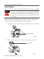
Install the Module
You can install or remove the module while chassis power is applied.
WARNING
!
When you insert or remove the module while backplane
power is on, an electrical arc can occur. This could cause
an explosion in hazardous location installations. Be sure
that power is removed or the area is nonhazardous before
proceeding.
Repeated electrical arcing causes excessive wear to contacts on both
the module and its mating connector. Worn contacts may create
electrical resistance that can affect module operation.
1. Align the circuit board with the top and bottom chassis guides.
Printed Circuit Board
20861-M
2. Slide the module into the chassis until module tabs ‘click’.
Locking Tab
20862-M
Publication 1756-IN580A-EN-P - March 2003
ControlLogix™ Hydraulic Servo Module 7
Key the Module and Removable Terminal Block/Interface Module
Use the wedge-shaped keying tabs and U-shaped keying bands to
prevent connecting the wrong wires to your module.
Key positions on the module that correspond to unkeyed positions
on the RTB. For example, if you key the first position on the module,
leave the first position on the RTB unkeyed.
1. To key the module, insert the U-shaped band, as shown.
U-shaped
bands
20850–M
2. Push the band until it snaps in place.
3. To key the RTB or IFM, insert the wedge-shaped tab with
rounded edge first, as shown.
Wedge-shaped tab
20851–M
4. Push the tab until it stops.
Reposition the tabs to rekey future module applications.
Publication 1756-IN580A-EN-P - March 2003
8 ControlLogix™ Hydraulic Servo Module
Wire a Removable Terminal Block (RTB)
Your 1756-HYD02 module uses two types of RTBs (each RTB comes
with housing) to connect wiring.
· Cage clamp - Catalog number 1756-TBCH
· Spring clamp - Catalog number 1756-TBS6H
Connect the wires as shown below.
Spring Clamp RTB
Cage Clamp RTB
1. Strip 7/16 inch (11mm) maximum
length of wire.
1. Strip 3/8 inch (9.5mm) maximum
length of wire.
2. Insert the screwdriver into the
inner hole of the RTB.
2. Insert the wire into the open terminal.
3. Turn the screw clockwise to close the
terminal on the wire.
3. Insert the wire into the
open terminal and
remove the screwdriver.
20860-M
20859-M
Publication 1756-IN580A-EN-P - March 2003
ControlLogix™ Hydraulic Servo Module 9
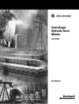
Wire to a Servo Module
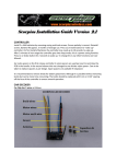
Use the wiring example in Figure 1 to wire to your module.
Figure 1
+OUT-0
-OUT-0
+ENABLE-0
-ENABLE-0
DRVFLT-0
CHASSIS
IN_COM
HOME-0
REG24V-0
REG5V-0
+OK
CHASSIS
+INT-0
-INT-0
+RET-0
-RET-0
LDT CMN
CHASSIS
+OUT-1
-OUT-1
+ENABLE-1
-ENABLE-1
DRVFLT-1
CHASSIS
IN_COM
HOME-1
REG24V-1
REG5V-1
-OK
CHASSIS
+INT-1
-INT-1
+RET-1
-RET-1
LDT CMN
CHASSIS
General cable
C0720
To valve
General cable
C0721
To valve or pump
General cable
C0720
General cable
C0720
To home
limit
switch
To
registration
sensor
General cable
C0722
To Linear
Displacement
Transducer
(LDT)
General cable
C0720
To E-stop relay coil
43394
NOTES: 1. This is a general wiring example illustrating Axis 1 wiring only. Other
configurations are possible with Axis wiring identical to Axis 1.
2. Make sure that any transducer connected to the 1756-HYD02 module
uses an external interrogation signal.
3. Do not exceed the specified isolation voltage between power sources.
Publication 1756-IN580A-EN-P - March 2003
10 ControlLogix™ Hydraulic Servo Module
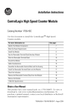
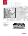
Wiring Registration Sensors
The registration inputs to the servo module can support 24V dc or
5V dc registration sensors. These inputs should be wired to receive
source current from the sensor. Current sinking sensor configurations
are not allowed because the registration input common (IN_ COM) is
shared with the other 24V dc servo module inputs.
Figure 2 - 24V Registration Sensor
24 V dc
Power
Supply
–
+
From
1756-HYD02
General cable
C0720
24 Volt
Registration
Sensor
Supply
Output
Common
REG24V
IN_COM
43395
Figure 3 - 5V Registration Sensor
5 V dc
Power
Supply
+
–
From
1756-HYD02
General cable
C0720
REG5V
IN_COM
5 Volt
Registration
Sensor
Supply
Output
Common
43395
Publication 1756-IN580A-EN-P - March 2003
ControlLogix™ Hydraulic Servo Module 11
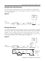
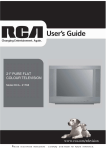
Wiring the Home Limit Switch Input
The home limit switch inputs to the servo module are designed for
24V dc nominal operation. These inputs should be wired for current
sourcing operation.
Figure 4
24 V dc
Power
Supply
+
–
From
1756-HYD02
HOME
IN_COM
General cable
C0720
43396
Wiring the OK Contacts
A set of isolated solid- state OK relay contacts is provided for optional
interface to an E- stop string, which controls power to the associated
pumps. The OK contacts are rated to drive an external 24V dc pilot
relay (for example, Allen-Bradley 700- HA32Z24) whose contacts can
be incorporated into the E- Stop string as in Figure 5.
Figure 5
24 V dc
Power
Supply
+
–
From
1756-HYD02
OK Pilot
Relay
+OK
-OK
General cable
C0720
OK Pilot
Relay
Start
Contacts
43397
CR1
Stop
CR1
M1
CR1
24V ac/dc or
120V ac
typical
43398
Publication 1756-IN580A-EN-P - March 2003
12 ControlLogix™ Hydraulic Servo Module
Assemble the Removable Terminal Block and the Housing
1. Align the grooves at the bottom of the housing with the side edges of the RTB.
Groove
Side edge of the RTB
Groove
Strain relief area
Side edge of the RTB
2. Slide the RTB into the housing until it snaps into place.
20858–M
Install the Removable Terminal Block onto the Module
WARNING
!
When you connect or disconnect the Removable Terminal Block
(RTB) with field side power applied, an electrical arc can occur.
This could cause an explosion in hazardous location
installations. Be sure that power is removed or the area is
nonhazardous before proceeding.
Before installing the RTB, make certain:
·
·
·
·
field-side wiring of the RTB has been completed.
the RTB housing is snapped in place on the RTB.
the RTB housing is closed.
the locking tab at the top of the module is unlocked.
1. Align the module and RTB guides to
make sure the module will seat properly.
2. Press quickly and evenly to seat the RTB
until the latches snap into place.
Locking tab
Module
guide
20853–M
RTB guides
Publication 1756-IN580A-EN-P - March 2003
20854–M
3. To lock the RTB on the module,
slide the locking tab down.
ControlLogix™ Hydraulic Servo Module 13
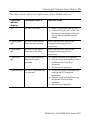
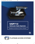
Checking the LED Indicators
The module uses a single bi-colored LED to indicate module OK
status and bi-colored LED indicators to show individual feedback
(FDBK) and drive (DRIVE) status for both axes.
During power up, the module completes an indicator test. The OK
indicator turns red for 1 second and then turns to flashing green if the
module passes all its self tests.
Understanding Module Status Using the OK Indicator
HYDRAULIC
AX0
AX1
FDBK
FDBK
DRIVE
DRIVE
OK indicator
OK
The table below offers an explanation of the OK indicator.
If the OK
indicator
displays:
The module status is:
Take this action:
Off
The module is not operating.
· Apply chassis power.
· Verify the module is completely
inserted in chassis and backplane.
Flashing green
light
The module has passed
internal diagnostics, but it is
not communicating axis
data over the backplane.
· None, if you have not configured the
module.
· If you have configured the module,
check the slot number in the
1756-HYD02 Properties dialog box.
Steady green
light
One of the following:
· Module is exchanging
axis data.
· The module is in the
normal operating state.
None
Publication 1756-IN580A-EN-P - March 2003
14 ControlLogix™ Hydraulic Servo Module
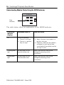
If the OK
indicator
displays:
The module status is:
Take this action:
Flashing red
light
One of the following:
· A major recoverable
failure has occurred.
· A communication fault,
timer fault, or
non-volatile memory
storage (NVS) update is
in progress.
· The OK contact has
opened.
If an NVS update is in progress,
complete the NVS update.
If an NVS update is not in progress:
· Check the Servo Fault word for the
source of the error.
· Clear the servo fault condition via
Motion Axis Fault Reset instruction.
· Resume normal operation.
· If the flashing persists, reconfigure
the module.
Steady red light
One of the following:
· A potential nonrecoverable fault has
occurred.
· The OK contact has
opened.
· Reboot the module.
· If the solid red persists, replace the
module.
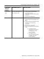
Understanding Module Status Using the FDBK Indicator
HYDRAULIC
Feedback
indicators
AX0
AX1
FDBK
FDBK
DRIVE
DRIVE
OK
IMPORTANT
Make sure that any transducer used with the
1756-HYD02 module uses an external
interrogation signal.
Publication 1756-IN580A-EN-P - March 2003
ControlLogix™ Hydraulic Servo Module 15
The table below offers an explanation of the FDBK indicator.
If the FDBK
indicator
displays:
The module status is:
Take this action:
Off
The axis is not used.
Flashing green
light
The axis is in the normal
servo loop inactive state.
None. The servo axis state can be
changed by executing motion
instructions.
Steady green
light
The axis is in the normal
servo loop active state.
None. The servo axis state can be
changed by executing motion
instructions.
Flashing red
light
The axis servo loop error
tolerance has been
exceeded.
· Correct the source of the problem.
· Clear the servo fault condition using
the Motion Axis Fault Reset
instruction.
· Resume normal operation.
Steady red light
An axis LDT feedback fault
has occurred.
· Correct the source of the problem by
checking the LDT and power
connections.
· Clear the servo fault condition using
the Motion Axis Fault Reset
instruction.
· Resume normal operation.
· None, if you are not using this axis.
· If you are using this axis, make sure
the module is configured and an axis
tag has been associated with the
module.
Publication 1756-IN580A-EN-P - March 2003
16 ControlLogix™ Hydraulic Servo Module
Understanding Module Status Using the DRIVE Indicator
HYDRAULIC
Drive
indicators
AX0
AX1
FDBK
FDBK
DRIVE
DRIVE
OK
The table below offers an explanation of the DRIVE indicator.
If the DRIVE
indicator
displays:
The module status is:
Off
One of the following:
· The axis is not used.
· The axis is a positiononly axis type.
Take this action:
· None, if the axis is not used or is a
position- only type.
· Otherwise, make sure the module is
configured, an axis tag has been
associated with the module, and the
axis type is servo.
Flashing green
light
The axis drive is in the
normal disabled state.
None. The servo axis state can be
changed by executing motion
instructions.
Steady green
light
The axis drive is in the
normal enabled state.
None. The servo axis state can be
changed by executing motion
instructions.
Publication 1756-IN580A-EN-P - March 2003
ControlLogix™ Hydraulic Servo Module 17
If the DRIVE
indicator
displays:
The module status is:
Flashing red
light
The axis drive output is in
the shutdown state.
· Check for faults that may have
generated this state.
· Execute the Shutdown Reset motion
instruction.
· Resume normal operation.
Steady red light
The axis drive is faulted.
· Check the drive status.
· Clear the Drive Fault condition at the
drive.
· Clear the servo fault condition using
the Motion Axis Fault Reset
instruction.
· Resume normal operation.
· Check the configuration for the Drive
Fault.
· If configured to be
normally open and there is
no voltage, this is the
normal condition.
· If configured to be
normally closed and 24V dc
is applied, this is the
normal condition.
Take this action:
Publication 1756-IN580A-EN-P - March 2003
18 ControlLogix™ Hydraulic Servo Module
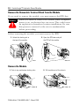
Remove the Removable Terminal Block from the Module
If you need to remove the module, you must remove the RTB first.
WARNING
!
When you insert or remove the module while backplane
power is on, an electrical arc can occur. This could cause
an explosion in hazardous location installations. Be sure
that power is removed or the area is nonhazardous
before proceeding.
Before removing the module, you must remove the RTB.
1. Unlock the locking tab at
the top of the module.
2. Open the RTB door and pull
the RTB off the module.
42517
20855–M
Remove the Module
1. Push in top and bottom locking tabs.
20856–M
Publication 1756-IN580A-EN-P - March 2003
2. Pull module out of the chassis.
20857–M
ControlLogix™ Hydraulic Servo Module 19
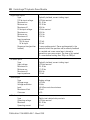
1756-HYD02 Specifications
Number of axes
Servo loop
Type
Gain resolution
Absolute position range
Rate
2 axes maximum
Proportional, integral and differential (PID) with
Feed-Forwards and Directional scaling
32- bit floating point
230,000 LDT counts
500Hz to 4kHz (Selectable)
Module location
1756 ControlLogix chassis
Module keying
Electronic
Power dissipation
5.5W maximum
Thermal dissipation
18.77 BTU/hr
Backplane current
5.1V dc @ 700mA and 24V dc @ 2.5mA
LDT input
Type
Resolution
Electrical Interface
Input impedance
Output Load
Transducer
PWM, Start/Stop rising or falling edge
less than 0.001 inch with single recirculation
Isolated 5V differential (RS-422 signal)
215 Ohm differential
100 Ohm minimum
Must use External Interrogation signal
Publication 1756-IN580A-EN-P - March 2003
20 ControlLogix™ Hydraulic Servo Module
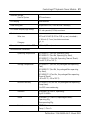
Registration inputs
Type
24V dc input voltage
Maximum on
Minimum on
Maximum off
5V dc input voltage
Maximum on
Minimum on
Maximum off
Input impedance
24V dc input
5V dc input
Response time (position
latched)
Optically isolated, current sinking input
+24V dc nominal
26. 4V dc
18. 5V dc
3.5V dc
+5V dc nominal
5.5V dc
3.7V dc
1.5V dc
1.2 kW
9.5 kW
1 servo update period - Servo update period is the
period at which the position and/or velocity feedback
is sampled and a new servo loop is closed to
generate a new servo output. The time of this period
is a user-defined setting from 250m s to 2000m s.
All other inputs
Type
Input voltage
Maximum on
Minimum on
Maximum off
Input impedance
Optically isolated, current sinking input
+24V dc nominal
26. 4V dc
17. 0V dc
8.5V dc
7.5 kW
Servo output
Type
Voltage range
Voltage resolution
Load
Maximum offset
Gain error
Analog voltage
±10V dc
16 bits
5.6 kOhms resistive minimum
25 mV
±4%
All other outputs
Type
Operating voltage
Maximum
Operating current
Solid-state isolated relay contacts
+24V dc nominal
26. 4V dc
75 mA
Publication 1756-IN580A-EN-P - March 2003
ControlLogix™ Hydraulic Servo Module 21
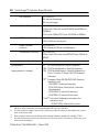
Isolation Voltage
User to System
30V continuous
RTB keying
User-defined
Field wiring arm
36-position RTB (1756-TBCH or -TBS6H)(1)
RTB screw torque (cage clamp)
4.4 inch-pounds (0.4Nm) maximum
Conductors
Wire size
Category
Screwdriver blade width for RTB
#22 to #14 AWG (0.324 to 2.08 sq. mm) stranded(1)
3/ 64 inch (1.2 mm) insulation maximum
2(2), (3)
1/8 inch (3.2mm) maximum
Environmental Conditions
Operating Temperature
IEC 60068-2-1 (Test Ad, Operating Cold),
IEC 60068-2-2 (Test Bd, Operating Dry Heat),
IEC 60068-2-14 (Test Nb, Operating Thermal Shock):
0 to 60°C (32 to 140°F)
Storage Temperature
IEC 60068-2-1 (Test Ab, Un-packaged Non-operating
Cold),
IEC 60068-2-2 (Test Bb, Un-packaged Non-operating
Dry Heat),
IEC 60068-2-14 (Test Na, Un-packaged Non-operating
Thermal Shock):
–40 to 85°C (–40 to 185°F)
Relative Humidity
IEC 60068-2-30 (Test Db, Un-packaged Non-operating
Damp Heat):
5 to 95% non-condensing
Vibration
IEC60068-2-6 (Test Fc, Operating):
2g @ 10-500Hz
Shock
IEC60068-2-27 (Test Ea, Unpackaged shock):
Operating 30g
Non-operating 50g
Emissions
CISPR 11:
Group 1, Class A
Publication 1756-IN580A-EN-P - March 2003
22 ControlLogix™ Hydraulic Servo Module
ESD Immunity
IEC 61000-4-2:
6kV contact discharges
8kV air discharges
Radiated RF Immunity
IEC 61000-4-3:
10V/m with 1kHz sine-wave 80%AM from 80MHz to
2000MHz
10V/m with 200Hz 50% Pulse 100%AM at 900Mhz
EFT/B Immunity
IEC 61000-4-4:
±2kV at 5kHz on signal ports
Surge Transient
Immunity
IEC 61000-4-5:
+2kV line-earth (CM) on shielded ports
Conducted RF Immunity
IEC 61000-4-6:
10Vrms with 1kHz sine-wave 80%AM from 150kHz to
80MHz
Enclosure Type Rating
None (open-style)
Certifications
(when product is marked)
UL UL Listed Industrial Control Equipment
CSA CSA Certified Process Control Equipment
CSA CSA Certified Process Control Equipment for
Class I, Division 2 Group A,B,C,D Hazardous
Locations
CE(4) European Union 89/336/EEC EMC Directive,
compliant with:
EN 50082-2; Industrial Immunity
EN 61326; Meas./Control/Lab., Industrial
Requirements
EN 61000-6-2; Industrial Immunity
EN 61000-6-4; Industrial Emissions
C-Tick(4) Australian Radiocommunications Act,
compliant with:
AS/NZS 2064; Industrial Emissions
(1)
(2)
(3)
(4)
Maximum wire size requires the extended-depth RTB housing (1756-TBE).
Use the conductor category information for planning conductor routing as described in the system
level installation manual.
Refer to Industrial Automation Wiring and Grounding Guidelines, publication number 1770-4.1.
See the Product Certification link at www.ab.com for Declarations of Conformity, Certificates, and
other certification details.
Publication 1756-IN580A-EN-P - March 2003
ControlLogix™ Hydraulic Servo Module 23
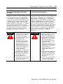
The following information applies when
operating this equipment in hazardous
locations:
Informations sur l’utilisation de cet équipement
en environnements dangereux :
Products marked “CL I, DIV 2, GP A, B, C, D” are
suitable for use in Class I Division 2 Groups A, B,
C, D, Hazardous Locations and nonhazardous
locations only. Each product is supplied with
markings on the rating nameplate indicating the
hazardous location temperature code. When
combining products within a system, the most
adverse temperature code (lowest “T” number)
may be used to help determine the overall
temperature code of the system. Combinations
of equipment in your system are subject to
investigation by the local Authority Having
Jurisdiction at the time of installation.
Les produits marqués "CL I, DIV 2, GP A, B, C, D" ne
conviennent qu’à une utilisation en environnements de
Classe I Division 2 Groupes A, B, C, D dangereux et
non dangereux. Chaque produit est livré avec des
marquages sur sa plaque d’identification qui indiquent
le code de température pour les environnements
dangereux. Lorsque plusieurs produits sont combinés
dans un système, le code de température le plus
défavorable (code de température le plus faible) peut
être utilisé pour déterminer le code de température
global du système. Les combinaisons d’équipements
dans le système sont sujettes à inspection par les
autorités locales qualifiées au moment de
l’installation.
WARNING
!
EXPLOSION HAZARD
· Do not disconnect equipment
unless power has been
removed or the area is
known to be nonhazardous.
· Do not disconnect
connections to this
equipment unless power
has been removed or the
area is known to be
nonhazardous. Secure any
external connections that
mate to this equipment by
using screws, sliding
latches, threaded
connectors, or other means
provided with this product.
· Substitution of components
may impair suitability for
Class I, Division 2.
· If this product contains
batteries, they must only be
changed in an area known
to be nonhazardous.
AVERTISSEMENT
!
RISQUE D’EXPLOSION
· Couper le courant ou s’assurer
que l’environnement est
classé non dangereux avant
de débrancher l'équipement.
· Couper le courant ou s'assurer
que l’environnement est
classé non dangereux avant
de débrancher les
connecteurs. Fixer tous les
connecteurs externes reliés à
cet équipement à l'aide de vis,
loquets coulissants,
connecteurs filetés ou autres
moyens fournis avec ce
produit.
· La substitution de composants
peut rendre cet équipement
inadapté à une utilisation en
environnement de Classe I,
Division 2.
· S’assurer que l’environnement
est classé non dangereux
avant de changer les piles.
Publication 1756-IN580A-EN-P - March 2003
Rockwell Automation Support
Rockwell Automation tests all of our products to ensure that they are
fully operational when shipped from the manufacturing facility.
If you are experiencing installation or startup problems, please
review the troubleshooting information contained in this publication
first. If you need technical assistance to get your module up and
running, please contact Customer Support (see the table below); our
trained technical specialists are available to help.
If the product is not functioning and needs to be returned, contact
your distributor. You must provide a Customer Support case number
to your distributor in order to complete the return process.
Phone
United States/Canada
1.440.646.5800
Outside United
States/Canada
You can access the phone number for your country
via the Internet:
1. Go to http://support.rockwellautomation.com/
2. Under Contacting Customer Support and Other
Countries, click on Click here
Internet
Worldwide
Go to http://support.rockwellautomation.com/
Publication 1756-IN580A-EN-P - March 2003
PN 957678-85
Copyright © 2003 Rockwell Automation, Inc. All rights reserved. Printed in the U.S.A.