1
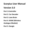
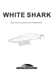
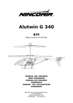
Scorpius Installation Guide Version 2.1
CONTROLLER
Install 2 x AAA batteries by removing casing and knob screws. Ensure polarity is correct. Reinstall
screws. Battery life approx. 3 months of average use. Press LC or brake button to “wake up”
controller. On first install of batteries the controller may need up to 10 seconds to wake up.
After 2 minutes of non-usage the controller goes into sleep mode, this is a power saving function,
Press LC or brake button for 2 seconds to wake up. To change ID or any other functions see User
Manual.
Ker nylon spacer on the first release controller 2 nylon spacers are used per post to centralise the
PCB in the handle. In the second release this was changed to one thicker nylon spacer. Care to be
taken to replace spacers as per design. Spare spacers are available if misplaced.
It is recommended to remove knobs for battery placement. Although it is possible without removing
knobs but can be more time consuming. The knobs should be replaced with 1mm or 1/16” spacing
off the face of the controller to ensure smooth operation.
CAR DECODER
Car Chip has 7 wires as follows:
Motor Wires: Blue and white pair:
Blue is positive, white is negative. Car should move in a forward direction once installed. If car goes
in reverse swap motor wires around. A ferrite and 10,000pF capacitor (103) and ferrite must be
installed on motor prior to connecting motor wires. Wires are then twisted before soldering. See
pictures.
Braid Wires :Green or Yellow pair:
Note: The first production run has green braid wires, however wires on the second run are yellow.
A ferrite and 10,000pF capacitor (103) and ferrite must be installed on guide connectors prior to
connecting motor wires. Wires are then twisted before soldering. See pictures.
Red and black pair with phototransistor attached: Installed 12mm offset to left as car is facing in a
forward direction and viewing from above the car whilst in an upright position. Wires to be twisted
before fixing in place. See pictures.
Use vernier callipers to mark distance from centreline of car to centre of LED hole position. De-burr
car chassis hole from above before fitting and gluing phototransistor. Ensure face of phototransistor
is on the same plane as the car chassis to maximise accuracy of lane changing and lap counting. Do
this by holding bottom of chassis up to light and use reflections to get a better idea if the
phototransistor is perpendicular to car chassis. The face of the phototransistor should be flush with
the bottom of the chassis to maximise accuracy. Scraping of the sensor on the track can inhibit
performance in which case the sensor should be replaced.
Antenna: Single black or blue wire on front face of PCB in extreme corner.
Note: The first production run has black antenna wire, however antenna wire on the second run is
blue.
Install antenna aiming away from PCB at 90 degrees and vertical if possible. It is recommended the
antenna extend into the cockpit if the cockpit is directly over the antenna.
Earth Wire: Single black or blue wire on front face of PCB in extreme corner.
Note: The first production run has a blue earth wire, however the earth wire on the second run is
black. The earth wire is the only wire soldered to the rear of the decoder.
General Notes:
Ensure no metal part of the car, eg axles, motor, magnet etc contact car decoder which should be
fixed in place to prevent it from moving. Shorting of motor wires will damage the decoder. Shorting
of braid wires will switch decoder off.
We recommend hot glue to fix photo-transistor sensor in place which can peel away and leave a
clean surface later. Do not use Superglue, Zap or similar glues. These make it impossible to remove
the phototransistor without damaging the chassis. These glues also emit a vapour that permanently
fogs the lens, which will result in poor lap counting and lane changing.
We recommend Blutac to fix car decoder in place which can peel away and leave a clean surface
later. Do not use Superglue, Zap or hot glue. Also be aware hot glue can warp a chassis if not enough
care taken.
Plan your install. Consider cockpit position before commencing install, sometimes rotating the
decoder 90 or 180 degrees can save having to re-install it.
TRACK POWER
1) A variable voltage power supply (recommended) is connected directly to rails. Positive is the right
rail looking from the top view in a forward direction. The power supply should be rated to 3A per
car. Eg 6 cars you will need 18A. The power supply must have a cut out or current limiting device
included. External fuses should be avoided if possible. Red wire is positive. Black wire is negative.
DONGLE
The dongle requires a driver be installed which is available from the website. Click on the CP-210X
program and follow the prompts. Once installed plug the dongle into any USB port. The computer
will automatically find the correct com port for you. Only one program can be opened at any one
time with one dongle. Two programs can operate simultaneously with 2 dongles.
To test dongle, go to Throttle Test program or Car Data program to see if dongle is picking up signal.
Dongle should be in an elevated position in room in view of the start finish line. Use 2, 3 or 5 metre
USB extension cable.
Important.
Use an “active” cable. These cost a bit more but have a built in amplifier to compensate for longer
cable lengths. Removing dongle from PC before closing program may cause computer to freeze.
Reboot PC.
Multiple Dongles
A Windows PC cannot install more than one CP210x device if they have the same VID (Vendor ID),
PID (Product ID), and Serial Number. The VID/PID/Serial number combination act as an address
for the device. In order to use multiple CP210x devices on the same PC, you will need to change
the serial number in the device from the default value using the CP21xxCustomizationUtility in
AN721:
http://www.silabs.com/Support%20Documents/...are/an721sw.zip
This utility may not be compatible with all versions of the driver, so you may need to upgrade your
driver to the latest version (v6.6.1):
http://www.silabs.com/products/mcu/Pages/U...VCPDrivers.aspx
After downloading the software, open the utility and connect one CP210x device to the PC. Then,
hit the Refresh button in the utility, and the device should appear. Change the serial number to
another value other than 0001, and hit the Program Device button. You should then be able to
connect multiple CP210x devices to the PC.
Dongle in direct view of all parts of track.
LANE BRAIN
The Scorpius Lane Brain can be used for 2 purposes
i)Lap-counting
Set LB to ID 0 using the LB set up program supplied. When the car passes over the LED beacons, the
car will send a lap count signal to the PC.
ii) Lane change functions
Lane Changer Lane Brains can be configured to transmit on Channels 0-31
The Lane Brains can have their ID configured using the LB set up program.
ROUTED TRACKS.
For routed tracks use of 3mm dia. IR LEDS is recommended due to easier install.
For sliding cars simply add more LEDs:
Lane Brain Wiring
The Lane Brain has 20 wires.
Power : Red is positive, black negative. Use 8.5-16V DC. Use only the same power supply that
drives the track. Power can be taken from adjacent rails. Do not power Lane Brains from an
independent power supply. It is important that the voltage to cars and Lane Brains is identical
anywhere from 8-16V DC.
Solenoid driver wires.
There are 4 pairs of solenoid wires.
Lane 1: A & B Car to go straight green pair. Car to change lanes black pair.
Lane 2: A & B Car to go straight orange pair. Car to change lanes blue pair.
Remember to go straight Ninco uses a sprung flipper and Carrera a mechanical switch, here those
wires not required can be trimmed off and ends insulated, or de-solder from board if skillful enough.
SSD XLC : 4 pairs of solenoid wires will be employed
SSD CLC: 2 pairs of solenoid wires will be employed.
Ninco XLC or double CLC: 2 pairs of solenoid wires will be employed. Green for lane 1 and orange for
lane 2. The other pairs are not required.
Ninco single LC: 1 pair of solenoid wires will be employed. Green for lane 1 or orange for lane 2. The
other pairs are not required.
Carrera XLC: 2 pairs of solenoid wires will be employed. Green for lane 1 and orange for lane 2. The
other pairs are not required.
Carrera single LC: 1 pair of solenoid wires will be employed. Green for lane 1 or orange for lane 2.
The other pairs are not required.
Timber tracks: If using Peco solenoid (which is actually 2 solenoids in one unit) 2 pairs of wire per
solenoid will be employed.
SCX: Scorpius cannot be used with SCX digital track system.
Each solenoid can be wired in any polarity.
Note the set up program allows the power to left and right solenoid (in the same lane) to
be swapped should they be wired in reverse. A handy tool.
LED Beacon wires:
4 pairs, each pair one colour and red. Red is positive, the coloured wire is
earth for all 4 LED driver sets. The colours distinguish the different sets.
Side looker type LEDs are factory fitted. These are flat and are the best for plastic track use.
Polarity must be observed if shortening or modifying wiring. If unused LEDs are removed the wire
pair must be soldered together and insulated. This is because the LEDS are wired in pairs in series.
Removing an LED will create an open circuit resulting in non-operation.
Lane 1 LC LED: Red and Brown
Lane 1 AC LED: Red and White
Lane 1 AC LED: Black and Red
Lane 2 AC LED: Blue and Red
Liven flipper wires: Blue liven flipper
goes to flipper in lane 1. Orange liven flipper wire goes to
flipper in lane 2. Use silicone wire similar to what is used for braids. This helps to keep flipper
movement smooth.
Reset switch: Should be installed within easy reach for use when reconfiguring Lane Brain.
Polarity to this switch is not critical. Extend wires if needed.
Power on LED: A green LED shines when the unit is turned on.
Straight and Change are solenoid wires. Do not mix wires from colour set to another.
LED INSTALLATION NO ANTI COLLISION
Allow 160-220mm from LED to tip of flipper depending on speed.
LED INSTALLATION WITH ANTI COLLISION
Allow 160-220mm from LED to tip of flipper depending on speed.
Allow 160-220mm from LC LED to AC LED depending on speed.
LED board. Trim as required to fit your situation. Use double sided on plastic tracks for easy removal.
Adding additional LEDs to the Lane Brain.
Where cars slide on corners add additional LEDs in series or as shown below.
LED board before adding additional LED
LED board after adding LEDs and moving earth wire as shown.
INSTALLATION INTO TYPICAL PLASTIC TRACK SYSTEM
Lane Brain Install tips:
1) Anti-collision Led beacons must be installed if anti-collision box is ticked during configuration. If
they have been installed and anti-collision is not required then they must be removed from track.
Taping over LKEDS does not work as the IR light still penetrates. If the car detects an anti-collision
beacon and it is not configured to anti-collision mode the operation will fail.
2 )Use hot glue to attach LED beacon boards to underside of plastic tracks. It removes and cleans up
easily.
3) Assemble one LC/LB at a time, fully test in situ before proceeding to the next one.
4) Each LB must be assigned a unique ID. Start/finish line is always 0. Any other lane changer can be
assigned any ID from 1-31 in ascending order. Numbering of LBs in pits does not require any
particular numbers as long as they ascend as you drive down pit lane and bays.
5) Lane Brains must be enclosed for rug racing. Nylon carpet and debris will cause PCB failure.
6) When re-flashing the LB, make sure the laptop is elevated off the floor and not within a metre.
This seems to give better results.
7 Reset button. If pressed put the LB into boot mode, ready to be re-flashed or reconfigured.
8) Each time you re-flash or reconfigure each LB you must turn off the power supply for 5 seconds
and back on. This switches it from boot mode into operation mode.
9 )Each time the LB goes into boot mode it will start operating any flippers back and forth after 10
seconds. This does 2 things. Firstly it shows it went into boot mode. Secondly it proves if solenoids
are working.
10 )If the LB power wires are attached and the green LED is not lit it means the polarity is incorrect,
or a faulty LB.
11) The antenna wire should be proud or to the side of the PCB and not laying across it. And at right
angles if possible.
12) Use connector plugs between track and LB for a “Quick Release” set up.
13) When reconfiguring multiple LBs in one go you can leave the switching off/on of the LBs to the
end to save turning off on each time. Only downfall here is each LC will ‘click-clack” until they are
reset to operation mode. This isn’t an issue, only noisy!
14) Use vernier callipers to accurately mark out position of LED holes in track and phototransistor
hole in car chassis. Use 1mm bit as pilot hole before increasing track LED beacons to 6mm dia. And
car chassis to 3mm. De-burr car chassis hole from above before fitting and gluing phototransistor.
For very fast track sections increase their hole size to 7-8 mm in diameter to maximise the window
of opportunity that the phototransistor has to see the LED in the track as it passes over.
15 )Use multimeter to check polarity of wires before and after connection of power wires.
16) Install LEDs flat approx. 4-5mm from the track surface. The dot in the centre of the LED should
be the centre of the hole.
17) LEDs should be fixed with double sided tape for plastic track. It is important the LED is 3 mm
from the track surface depending on the speed of that particular track section.
Reset switch
Used in conjunction with reflashing and reconfiguring processes only.
Antenna
Should be at 90 degrees to PCB if possible.
Lane Brain Set up program.
See User Manual
END OF DOCUMENT