1
Technical Reference
DAS 9200
Technician’s Reference
070-5959-09
Warning
The servicing instructions are for use by qualified
personnel only. To avoid personal injury, do not
perform any servicing unless you are qualified to
do so. Refer to all safety summaries prior to
performing service.
Copyright Tektronix, Inc. All rights reserved. Licensed software products are owned by Tektronix or its suppliers and
are protected by United States copyright laws and international treaty provisions.
Use, duplication, or disclosure by the Government is subject to restrictions as set forth in subparagraph (c)(1)(ii) of the
Rights in Technical Data and Computer Software clause at DFARS 252.227-7013, or subparagraphs (c)(1) and (2) of the
Commercial Computer Software – Restricted Rights clause at FAR 52.227-19, as applicable.
Tektronix products are covered by U.S. and foreign patents, issued and pending. Information in this publication supercedes
that in all previously published material. Specifications and price change privileges reserved.
Printed in the U.S.A.
Tektronix, Inc., P.O. Box 1000, Wilsonville, OR 97070–1000
TEKTRONIX and TEK are registered trademarks of Tektronix, Inc.
DASNT and DASXP are trademarks of Tektronix, Inc.
WARRANTY
Tektronix warrants that this product will be free from defects in materials and workmanship for a period of one (1) year
from the date of shipment. If any such product proves defective during this warranty period, Tektronix, at its option, either
will repair the defective product without charge for parts and labor, or will provide a replacement in exchange for the
defective product.
In order to obtain service under this warranty, Customer must notify Tektronix of the defect before the expiration of the
warranty period and make suitable arrangements for the performance of service. Tektronix will provide such service at
Customer’s site without charge during the warranty period, if the service is performed within the normal on-site service
area. Tektronix will provide on-site service outside the normal on-site service area only upon prior agreement and subject
to payment of all travel expenses by Customer. When or where on-site service is not available, Customer shall be
responsible for packaging and shipping the defective product to the service center designated by Tektronix, with shipping
charges prepaid. Tektronix shall pay for the return of the product to Customer if the shipment is to a location within the
country in which the Tektronix service center is located. Customer shall be responsible for paying all shipping charges,
duties, taxes, and any other charges for products returned to any other locations.
This warranty shall not apply to any defect, failure or damage caused by improper use or improper or inadequate
maintenance and care. Tektronix shall not be obligated to furnish service under this warranty a) to repair damage resulting
from attempts by personnel other than Tektronix representatives to install, repair or service the product; b) to repair
damage resulting from improper use or connection to incompatible equipment; or c) to service a product that has been
modified or integrated with other products when the effect of such modification or integration increases the time or
difficulty of servicing the product.
THIS WARRANTY IS GIVEN BY TEKTRONIX WITH RESPECT TO THIS PRODUCT IN LIEU OF ANY
OTHER WARRANTIES, EXPRESSED OR IMPLIED. TEKTRONIX AND ITS VENDORS DISCLAIM ANY
IMPLIED WARRANTIES OF MERCHANTABILITY OR FITNESS FOR A PARTICULAR PURPOSE.
TEKTRONIX’ RESPONSIBILITY TO REPAIR OR REPLACE DEFECTIVE PRODUCTS IS THE SOLE AND
EXCLUSIVE REMEDY PROVIDED TO THE CUSTOMER FOR BREACH OF THIS WARRANTY. TEKTRONIX
AND ITS VENDORS WILL NOT BE LIABLE FOR ANY INDIRECT, SPECIAL, INCIDENTAL, OR
CONSEQUENTIAL DAMAGES IRRESPECTIVE OF WHETHER TEKTRONIX OR THE VENDOR HAS
ADVANCE NOTICE OF THE POSSIBILITY OF SUCH DAMAGES.
Table of Contents
General Safety Summary . . . . . . . . . . . . . . . . . . . . . . . . . . . . . . . . . . . .
Service Safety Summary . . . . . . . . . . . . . . . . . . . . . . . . . . . . . . . . . . . . .
Preface . . . . . . . . . . . . . . . . . . . . . . . . . . . . . . . . . . . . . . . . . . . . . . . . . . .
xi
xv
xvii
Introduction to DAS Hardware
Introduction to DAS Hardware . . . . . . . . . . . . . . . . . . . . . . . . . . . . . . .
1–1
Mainframes and Terminals . . . . . . . . . . . . . . . . . . . . . . . . . . . . . . . . . . . . . . . . . .
Terminals . . . . . . . . . . . . . . . . . . . . . . . . . . . . . . . . . . . . . . . . . . . . . . . . . . . .
Mainframe Hardware . . . . . . . . . . . . . . . . . . . . . . . . . . . . . . . . . . . . . . . . . .
Mainframe Power Requirements . . . . . . . . . . . . . . . . . . . . . . . . . . . . . . . . .
DAS with Option 04 . . . . . . . . . . . . . . . . . . . . . . . . . . . . . . . . . . . . . . . . . . .
DAS 92E9 Expansion Mainframe . . . . . . . . . . . . . . . . . . . . . . . . . . . . . . . .
Acquisition and Pattern Generation Modules . . . . . . . . . . . . . . . . . . . . . . . . . . .
1–2
1–3
1–3
1–8
1–12
1–14
1–16
Maintenance . . . . . . . . . . . . . . . . . . . . . . . . . . . . . . . . . . . . . . . . . . . . . . .
2–1
Preventive Maintenance . . . . . . . . . . . . . . . . . . . . . . . . . . . . . . . . . . . . . . . . . . . .
Static Precautions . . . . . . . . . . . . . . . . . . . . . . . . . . . . . . . . . . . . . . . . . . . . .
Cleaning Guidelines . . . . . . . . . . . . . . . . . . . . . . . . . . . . . . . . . . . . . . . . . . .
Mainframe . . . . . . . . . . . . . . . . . . . . . . . . . . . . . . . . . . . . . . . . . . . . . . . . . . .
Terminal and Keyboard . . . . . . . . . . . . . . . . . . . . . . . . . . . . . . . . . . . . . . . . .
DAS Modules . . . . . . . . . . . . . . . . . . . . . . . . . . . . . . . . . . . . . . . . . . . . . . . .
92HS8/8E Cabinet . . . . . . . . . . . . . . . . . . . . . . . . . . . . . . . . . . . . . . . . . . . .
Corrective Maintenance . . . . . . . . . . . . . . . . . . . . . . . . . . . . . . . . . . . . . . . . . . . .
Inspection . . . . . . . . . . . . . . . . . . . . . . . . . . . . . . . . . . . . . . . . . . . . . . . . . . .
Obtaining Replacements . . . . . . . . . . . . . . . . . . . . . . . . . . . . . . . . . . . . . . . .
Selecting the Line Voltage and Replacing the Line Fuse . . . . . . . . . . . . . . .
Replacing the Battery on the DAS 9219/9220 Controller Board . . . . . . . . .
Disposing the Lithium Battery . . . . . . . . . . . . . . . . . . . . . . . . . . . . . . . . . . .
2–1
2–1
2–2
2–3
2–4
2–5
2–5
2–6
2–6
2–6
2–6
2–14
2–16
Maintenance
Disassembly/Reassembly Procedures
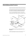
Disassembly/Reassembly Procedures . . . . . . . . . . . . . . . . . . . . . . . . . .
3–1
General Precautions . . . . . . . . . . . . . . . . . . . . . . . . . . . . . . . . . . . . . . . . . . . . . . .
Tools Required . . . . . . . . . . . . . . . . . . . . . . . . . . . . . . . . . . . . . . . . . . . . . . . . . . .
Disassembly/Reassembly of the Mainframes . . . . . . . . . . . . . . . . . . . . . . . . . . .
3–2
3–2
3–3
DAS 9200 Technician’s Reference
i
Table of Contents
Procedure 1:Removing the Mainframe Top Cover . . . . . . . . . . . . . . . . . . . .
Procedure 2:Removing a Module From the Card Cage . . . . . . . . . . . . . . . .
Procedure 2a:Removing the 92LANSE Module . . . . . . . . . . . . . . . . . . . . .
Procedure 3:Removing the Front Panel . . . . . . . . . . . . . . . . . . . . . . . . . . . .
Procedure 4:Removing the Fan . . . . . . . . . . . . . . . . . . . . . . . . . . . . . . . . . . .
Procedure 5:Removing the Media Frame . . . . . . . . . . . . . . . . . . . . . . . . . . .
Procedure 6:Removing the Disk Drives From the Media Frame . . . . . . . . .
Procedure 7:Removing the Power Supply . . . . . . . . . . . . . . . . . . . . . . . . . .
Procedure 8:Removing the Card Cage . . . . . . . . . . . . . . . . . . . . . . . . . . . . .
Procedure 9:Removing the Controller Board . . . . . . . . . . . . . . . . . . . . . . . .
Procedure 10:Removing and Disassembling the Expansion Cable
(DAS 92E9 only) . . . . . . . . . . . . . . . . . . . . . . . . . . . . . . . . . . . . . .
Procedure 11:Removing the Expansion Slave Board (DAS 92E9 only) . . .
Procedure 12: Removing the Backplane . . . . . . . . . . . . . . . . . . . . . . . . . . . .
Disassembly/Reassembly of the 92HS8 Cabinet . . . . . . . . . . . . . . . . . . . . . . . . .
Procedure 1:Removing the 92HS8 Cabinet Covers . . . . . . . . . . . . . . . . . . .
Procedure 2:Elevating the 92HS8 Memory Board . . . . . . . . . . . . . . . . . . . .
Procedure 3:Removing the 92HS8 Power Supply . . . . . . . . . . . . . . . . . . . .
Procedure 4:Removing the 92HS8 Cooling Fans . . . . . . . . . . . . . . . . . . . . .
Procedure 5:Replacing 92HS8 Probes . . . . . . . . . . . . . . . . . . . . . . . . . . . . .
Disassembly/Reassembly of Probes . . . . . . . . . . . . . . . . . . . . . . . . . . . . . . . . . . .
P6461/E Data Acquisition Probe . . . . . . . . . . . . . . . . . . . . . . . . . . . . . . . . .
P6460 Data Acquisition Probe . . . . . . . . . . . . . . . . . . . . . . . . . . . . . . . . . . .
P6464 Pattern Generator Probe . . . . . . . . . . . . . . . . . . . . . . . . . . . . . . . . . . .
P6465 Pattern Generator Probe . . . . . . . . . . . . . . . . . . . . . . . . . . . . . . . . . . .
P6463/A Pattern Generator Probe . . . . . . . . . . . . . . . . . . . . . . . . . . . . . . . . .
92A60/90 Buffer Probe . . . . . . . . . . . . . . . . . . . . . . . . . . . . . . . . . . . . . . . . .
Terminals . . . . . . . . . . . . . . . . . . . . . . . . . . . . . . . . . . . . . . . . . . . . . . . . . . . .
3–3
3–5
3–6
3–6
3–7
3–8
3–9
3–15
3–18
3–20
3–20
3–21
3–22
3–22
3–23
3–23
3–24
3–24
3–25
3–26
3–27
3–27
3–27
3–28
3–28
3–29
3–29
Troubleshooting . . . . . . . . . . . . . . . . . . . . . . . . . . . . . . . . . . . . . . . . . . . .
4–1
Mainframe Troubleshooting Overview . . . . . . . . . . . . . . . . . . . . . . . . . . . . . . . .
Module Troubleshooting Overview . . . . . . . . . . . . . . . . . . . . . . . . . . . . . . . . . . .
Power-On Diagnostics . . . . . . . . . . . . . . . . . . . . . . . . . . . . . . . . . . . . . . . . . . . . .
9200T Terminal Diagnostics . . . . . . . . . . . . . . . . . . . . . . . . . . . . . . . . . . . . .
9201T Terminal Diagnostics . . . . . . . . . . . . . . . . . . . . . . . . . . . . . . . . . . . . .
9202XT and 9203XT Terminal Diagnostics . . . . . . . . . . . . . . . . . . . . . . . .
9204XT, 9205XT, and 9206XT Terminal Diagnostics . . . . . . . . . . . . . . . .
DAS Mainframe Diagnostics . . . . . . . . . . . . . . . . . . . . . . . . . . . . . . . . . . . .
92LAN Diagnostics . . . . . . . . . . . . . . . . . . . . . . . . . . . . . . . . . . . . . . . . . . . . . . .
Error Codes . . . . . . . . . . . . . . . . . . . . . . . . . . . . . . . . . . . . . . . . . . . . . . . . . .
92LAN Boot-Up Status . . . . . . . . . . . . . . . . . . . . . . . . . . . . . . . . . . . . . . . . .
Extended 92LAN Diagnostics . . . . . . . . . . . . . . . . . . . . . . . . . . . . . . . . . . .
Cable Construction . . . . . . . . . . . . . . . . . . . . . . . . . . . . . . . . . . . . . . . . . . . .
4–1
4–2
4–3
4–3
4–6
4–10
4–13
4–15
4–37
4–38
4–39
4–40
4–43
Troubleshooting
ii
DAS 9200 Technician’s Reference
Table of Contents
Mainframe Troubleshooting . . . . . . . . . . . . . . . . . . . . . . . . . . . . . . . . . . . . . . . . .
Power Supply Check . . . . . . . . . . . . . . . . . . . . . . . . . . . . . . . . . . . . . . . . . . .
Power Control Signals . . . . . . . . . . . . . . . . . . . . . . . . . . . . . . . . . . . . . . . . .
DIP Switches on the Controller Board . . . . . . . . . . . . . . . . . . . . . . . . . . . . .
RS-232 Ports . . . . . . . . . . . . . . . . . . . . . . . . . . . . . . . . . . . . . . . . . . . . . . . . .
Hard and Floppy Disk Drive Power Connector . . . . . . . . . . . . . . . . . . . . . .
Hard Disk Drive Switch and Jumper Positions . . . . . . . . . . . . . . . . . . . . . . .
Floppy Disk Drive Jumper Positions . . . . . . . . . . . . . . . . . . . . . . . . . . . . . .
Floppy Disk Drive Strapping on the Controller Board . . . . . . . . . . . . . . . . .
Other Controller Board Jumpers . . . . . . . . . . . . . . . . . . . . . . . . . . . . . . . . . .
Loading System Software . . . . . . . . . . . . . . . . . . . . . . . . . . . . . . . . . . . . . . . . . .
Hard Disk Format Utility . . . . . . . . . . . . . . . . . . . . . . . . . . . . . . . . . . . . . . .
DAS 9221 SCSI Hard Disk Format Utility Menus . . . . . . . . . . . . . . . . . . . .
DAS 9219/9220 ST506 Hard Disk Format Utility Menus . . . . . . . . . . . . . .
File System Make Utility . . . . . . . . . . . . . . . . . . . . . . . . . . . . . . . . . . . . . . .
File System Install Utility . . . . . . . . . . . . . . . . . . . . . . . . . . . . . . . . . . . . . . .
Configuration Utility . . . . . . . . . . . . . . . . . . . . . . . . . . . . . . . . . . . . . . . . . . .
Optional System Software . . . . . . . . . . . . . . . . . . . . . . . . . . . . . . . . . . . . . .
Application Software . . . . . . . . . . . . . . . . . . . . . . . . . . . . . . . . . . . . . . . . . .
Operator’s Checkout Procedure . . . . . . . . . . . . . . . . . . . . . . . . . . . . . . . . . . . . . .
9200T or 9201T Terminal Power-Up Diagnostics . . . . . . . . . . . . . . . . . . . .
Power-Up Self-Test . . . . . . . . . . . . . . . . . . . . . . . . . . . . . . . . . . . . . . . . . . . .
X Terminal Power-Up Diagnostics . . . . . . . . . . . . . . . . . . . . . . . . . . . . . . . .
Mainframe Power-Up Diagnostics . . . . . . . . . . . . . . . . . . . . . . . . . . . . . . . .
Troubleshooting the DAS Modules . . . . . . . . . . . . . . . . . . . . . . . . . . . . . . . . . . .
92A16/16E Troubleshooting . . . . . . . . . . . . . . . . . . . . . . . . . . . . . . . . . . . . .
92A60/90 Troubleshooting . . . . . . . . . . . . . . . . . . . . . . . . . . . . . . . . . . . . . .
92A96 and 92C96 Troubleshooting . . . . . . . . . . . . . . . . . . . . . . . . . . . . . . .
92HS8 Troubleshooting . . . . . . . . . . . . . . . . . . . . . . . . . . . . . . . . . . . . . . . .
92S16/32 Troubleshooting . . . . . . . . . . . . . . . . . . . . . . . . . . . . . . . . . . . . . .
92SX109/118 Troubleshooting . . . . . . . . . . . . . . . . . . . . . . . . . . . . . . . . . . .
92C01/02 Troubleshooting . . . . . . . . . . . . . . . . . . . . . . . . . . . . . . . . . . . . . .
DAS LAN Troubleshooting . . . . . . . . . . . . . . . . . . . . . . . . . . . . . . . . . . . . . . . . .
X Terminal Traits . . . . . . . . . . . . . . . . . . . . . . . . . . . . . . . . . . . . . . . . . . . . .
DAS Stand-Alone LAN Troubleshooting . . . . . . . . . . . . . . . . . . . . . . . . . . .
LAN Network Troubleshooting . . . . . . . . . . . . . . . . . . . . . . . . . . . . . . . . . .
LAN Communications . . . . . . . . . . . . . . . . . . . . . . . . . . . . . . . . . . . . . . . . .
Snoopy Mode for ARP and TCP/IP . . . . . . . . . . . . . . . . . . . . . . . . . . . . . . .
4–43
4–43
4–44
4–45
4–46
4–47
4–47
4–56
4–67
4–67
4–69
4–70
4–71
4–76
4–83
4–91
4–96
4–108
4–109
4–110
4–110
4–110
4–111
4–111
4–112
4–112
4–114
4–114
4–119
4–121
4–121
4–121
4–122
4–122
4–123
4–126
4–130
4–132
General Circuit Functions
General Circuit Functions . . . . . . . . . . . . . . . . . . . . . . . . . . . . . . . . . . .
5–1
DAS Mainframe . . . . . . . . . . . . . . . . . . . . . . . . . . . . . . . . . . . . . . . . . . . . . . . . . .
Backplane Board . . . . . . . . . . . . . . . . . . . . . . . . . . . . . . . . . . . . . . . . . . . . . .
Controller Board . . . . . . . . . . . . . . . . . . . . . . . . . . . . . . . . . . . . . . . . . . . . . .
Memory Board (DAS 9219/9220 Only) . . . . . . . . . . . . . . . . . . . . . . . . . . . .
Hard and Floppy Disk Drives . . . . . . . . . . . . . . . . . . . . . . . . . . . . . . . . . . . .
Power Supply . . . . . . . . . . . . . . . . . . . . . . . . . . . . . . . . . . . . . . . . . . . . . . . .
DAS 92E9 Expansion Mainframe . . . . . . . . . . . . . . . . . . . . . . . . . . . . . . . . . . . .
Expansion Slave Board . . . . . . . . . . . . . . . . . . . . . . . . . . . . . . . . . . . . . . . . . . . .
5–1
5–2
5–5
5–11
5–11
5–13
5–13
5–15
DAS 9200 Technician’s Reference
iii
Table of Contents
92A16/16E Data Acquisition Module . . . . . . . . . . . . . . . . . . . . . . . . . . . . . . . . .
P6461/E Data Acquisition Probe . . . . . . . . . . . . . . . . . . . . . . . . . . . . . . . . .
P6460 Data Acquisition Probe . . . . . . . . . . . . . . . . . . . . . . . . . . . . . . . . . . .
92A60/90 Data Acquisition Module . . . . . . . . . . . . . . . . . . . . . . . . . . . . . . . . . .
92A60/90 Controller Board . . . . . . . . . . . . . . . . . . . . . . . . . . . . . . . . . . . . .
92A60/90 Memory Board . . . . . . . . . . . . . . . . . . . . . . . . . . . . . . . . . . . . . . .
92A60/90 Buffer Probe . . . . . . . . . . . . . . . . . . . . . . . . . . . . . . . . . . . . . . . . .
92A96 and 92C96 Data Acquisition Modules . . . . . . . . . . . . . . . . . . . . . . . . . . .
92HS8/8E High-Speed Data Acquisition Module . . . . . . . . . . . . . . . . . . . . . . . .
92S16 Pattern Generation Module . . . . . . . . . . . . . . . . . . . . . . . . . . . . . . . . . . . .
92S32 Pattern Generation Module . . . . . . . . . . . . . . . . . . . . . . . . . . . . . . . . . . . .
P6464 and P6465 Pattern Generation Probes . . . . . . . . . . . . . . . . . . . . . . . .
P6463A Pattern Generation Probe . . . . . . . . . . . . . . . . . . . . . . . . . . . . . . . .
92SX109/118 Pattern Generation Module . . . . . . . . . . . . . . . . . . . . . . . . . . . . . .
92C01/02/03 GPIB and Expansion Modules . . . . . . . . . . . . . . . . . . . . . . . . . . . .
92LAN Module . . . . . . . . . . . . . . . . . . . . . . . . . . . . . . . . . . . . . . . . . . . . . . . . . .
92LANSE Module . . . . . . . . . . . . . . . . . . . . . . . . . . . . . . . . . . . . . . . . . . . . . . . .
5–16
5–17
5–17
5–17
5–18
5–19
5–19
5–20
5–21
5–23
5–25
5–25
5–26
5–26
5–27
5–29
5–30
Replaceable Electrical Parts
Replaceable Electrical Parts . . . . . . . . . . . . . . . . . . . . . . . . . . . . . . . . . .
6–1
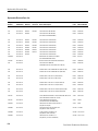
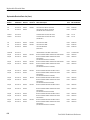
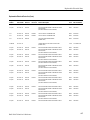
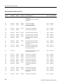
Parts Ordering Information . . . . . . . . . . . . . . . . . . . . . . . . . . . . . . . . . . . . . . . . .
Using the Replaceable Electrical Parts List . . . . . . . . . . . . . . . . . . . . . . . . . . . . .
6–1
6–1
Replaceable Mechanical Parts
Replaceable Mechanical Parts . . . . . . . . . . . . . . . . . . . . . . . . . . . . . . . .
7–1
Parts Ordering Information . . . . . . . . . . . . . . . . . . . . . . . . . . . . . . . . . . . . . . . . .
Using the Replaceable Mechanical Parts List . . . . . . . . . . . . . . . . . . . . . . . . . . .
7–1
7–1
Diagrams
Diagrams . . . . . . . . . . . . . . . . . . . . . . . . . . . . . . . . . . . . . . . . . . . . . . . . .
iv
7–81
DAS 9200 Technician’s Reference
Table of Contents
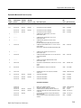
List of Figures
Figure 1–1: DAS Basic Configurations . . . . . . . . . . . . . . . . . . . . . . . . .
1–1
Figure 1–2: Master Mainframe Internal Components (Memory Board in
Slot 1 for DAS 9219/9220) . . . . . . . . . . . . . . . . . . . . . . . . . . . . . . . .
1–4
Figure 1–3: DAS Master Mainframe Connected with One Expansion
Mainframe . . . . . . . . . . . . . . . . . . . . . . . . . . . . . . . . . . . . . . . . . . . . .
1–14
Figure 1–4: Twenty-Eight Slots Available with One Master and Three
Expansion Mainframes . . . . . . . . . . . . . . . . . . . . . . . . . . . . . . . . . . .
1–15
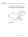
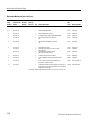
Figure 2–1: Location of Power Supply Frame Screws . . . . . . . . . . . . .
Figure 2–2: Location of Line Voltage Selection Jacks . . . . . . . . . . . . .
Figure 2–3: Position of Line Voltage Selection Jacks for 115 V or 230 V
Operation . . . . . . . . . . . . . . . . . . . . . . . . . . . . . . . . . . . . . . . . . . . . . .
Figure 2–4: Location of DAS 9221 Back Panel Fuse and Line Voltage
Indicator Knob (DAS 9219/9220 Look Similar) . . . . . . . . . . . . . . .
Figure 2–5: Location of AC Voltage Selector Switches on the 9200T
Figure 2–6: Location of the Line Voltage Selector and Line Fuse
Behind the 92HS8/8E Side Panel . . . . . . . . . . . . . . . . . . . . . . . . . . .
Figure 2–7: Back Panel Location of the 92HS8 Line Voltage
Indicator Screw . . . . . . . . . . . . . . . . . . . . . . . . . . . . . . . . . . . . . . . . .
Figure 2–8: Location of C921 on Mainframe Controller Board . . . . .
2–7
2–8
2–8
2–9
2–10
2–12
2–13
2–15
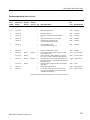
Figure 3–1: DAS Mainframe Internal Components (Memory Board in
Slot 1 for DAS 9219/9220) . . . . . . . . . . . . . . . . . . . . . . . . . . . . . . . .
3–1
Figure 3–2: Removing the Mainframe Top Cover . . . . . . . . . . . . . . . .
3–4
Figure 3–3: Ejector Tools and Location of Card-Cage
Door Fasteners . . . . . . . . . . . . . . . . . . . . . . . . . . . . . . . . . . . . . . . . .
3–5
Figure 3–4: Location of Latches for Removing the Front Panel . . . .
3–7
Figure 3–5: Location of Screws for Removing the Media Frame . . . .
3–9
Figure 3–6: Typical Cable Connections for Fixed-Mount Hard and Floppy
Disk Drives for DAS 9219 and DAS 9220 Mainframes . . . . . . . . .
3–11
Figure 3–7: Typical Cable Connections for Fixed-Mount Hard and Floppy
Disk Drives For DAS 9221 Mainframes . . . . . . . . . . . . . . . . . . . . .
3–12
Figure 3–8: Folding the Ribbon Cables . . . . . . . . . . . . . . . . . . . . . . . . .
3–13
Figure 3–9: Removable 20 Mbyte Drive in DAS 9219/9220
Media Frame . . . . . . . . . . . . . . . . . . . . . . . . . . . . . . . . . . . . . . . . . . .
3–14
Figure 3–10: Removable Hard Disk Drive in a Media Frame . . . . . .
3–15
Figure 3–11: Location of Screws for Removing the Mainframe
Power Supply . . . . . . . . . . . . . . . . . . . . . . . . . . . . . . . . . . . . . . . . . . .
3–16
DAS 9200 Technician’s Reference
v
Table of Contents
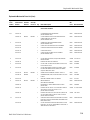
Figure 3–12: Back Panel Screw Locations for Removing the
Card Cage . . . . . . . . . . . . . . . . . . . . . . . . . . . . . . . . . . . . . . . . . . . . .
Figure 3–13: Bottom-front Screw Locations for Removing the
Card Cage . . . . . . . . . . . . . . . . . . . . . . . . . . . . . . . . . . . . . . . . . . . . .
Figure 3–14: Location of Screws for Elevating the 92HS8
Memory Board . . . . . . . . . . . . . . . . . . . . . . . . . . . . . . . . . . . . . . . . .
Figure 3–15: Location of Screws for Removing the 92HS8
Power Supply . . . . . . . . . . . . . . . . . . . . . . . . . . . . . . . . . . . . . . . . . . .
3–18
3–19
3–24
3–26
Figure 4–1: Location of SELF TEST and RESET Buttons on the 9200T
Rear Panel . . . . . . . . . . . . . . . . . . . . . . . . . . . . . . . . . . . . . . . . . . . . .
4–4
Figure 4–2: Location of S TEST and RESET Buttons on the 9201T
Front Panel . . . . . . . . . . . . . . . . . . . . . . . . . . . . . . . . . . . . . . . . . . . .
4–7
Figure 4–3: Extended Self Test Main Menu . . . . . . . . . . . . . . . . . . . . .
4–10
Figure 4–4: Extended Self Test Main Menu with Peripheral Tests . .
4–12
Figure 4–5: Peripheral Tests Menu . . . . . . . . . . . . . . . . . . . . . . . . . . . .
4–12
Figure 4–6: Local Self Test Menu . . . . . . . . . . . . . . . . . . . . . . . . . . . . .
4–13
Figure 4–7: Extended Self Test Main Menu . . . . . . . . . . . . . . . . . . . . .
4–14
Figure 4–8: Floppy and Hard Disk Drive Power Connector. . . . . . . .
4–47
Figure 4–9: Switch Locations on the 10 Mbyte Hard Disk Drive CircuitBoard (Factory Settings Shown) . . . . . . . . . . . . . . . . . . . . . . . . . . .
4–48
Figure 4–10: Jumper Locations on the 20 Mbyte Fixed Hard Disk Drive
(Factory Settings Shown) . . . . . . . . . . . . . . . . . . . . . . . . . . . . . . . . .
4–49
Figure 4–11: Jumper Locations on the 20 Mbyte Removable Hard Disk
Drive (Factory Settings Shown) . . . . . . . . . . . . . . . . . . . . . . . . . . . .
4–50
Figure 4–12: Jumper Locations on the 5.25-Inch 40 Mbyte Hard Disk
Drive (Factory Settings Shown) . . . . . . . . . . . . . . . . . . . . . . . . . . . .
4–51
Figure 4–13: Jumper Locations on the 3.5-Inch 40 Mbyte Hard Disk
Drive (Factory Settings Shown) . . . . . . . . . . . . . . . . . . . . . . . . . . . .
4–52
Figure 4–14: Jumper Locations on the 3.5-Inch 80 Mbyte Hard Disk
Drive (Factory Settings Shown) . . . . . . . . . . . . . . . . . . . . . . . . . . . .
4–53
Figure 4–15: Jumper Locations on the 100 Mbyte Hard Disk Drive
(Factory Settings Shown) . . . . . . . . . . . . . . . . . . . . . . . . . . . . . . . . .
4–54
Figure 4–16: Jumper Locations on the 127, 170, and 270 Mbyte Hard
Disk Drives (Factory Settings Shown) . . . . . . . . . . . . . . . . . . . . . .
4–55
Figure 4–17: Jumper Locations on the 1.2 Gbyte Hard Disk Drive
(Factory Settings Shown) . . . . . . . . . . . . . . . . . . . . . . . . . . . . . . . . .
4–56
Figure 4–18: Jumper Locations on the 3.5-inch 1.44 Mbyte Teac
Model FD-235HF-2301 Floppy Disk Drive
(Factory Settings Shown) . . . . . . . . . . . . . . . . . . . . . . . . . . . . . . . . .
4–57
vi
DAS 9200 Technician’s Reference
Table of Contents
Figure 4–19: Jumper Locations on the 3.5-inch 1.44 Mbyte Teac
Model FD-235HF-6529 Floppy Disk Drive
(Factory Settings Shown) . . . . . . . . . . . . . . . . . . . . . . . . . . . . . . . . .
Figure 4–20: Jumper Locations on the 3.5-inch 1.44 Mbyte Teac
Model FD-235HF-7529 Floppy Disk Drive
(Factory Settings Shown) . . . . . . . . . . . . . . . . . . . . . . . . . . . . . . . . .
Figure 4–21: Jumper Locations on the Model JU455-5 400 Kbyte
Floppy Disk Drive (Factory Settings Shown) . . . . . . . . . . . . . . . . .
Figure 4–22: Jumper Locations on the Model JU455-7 400 Kbyte
Floppy Disk Drive (Factory Settings Shown) . . . . . . . . . . . . . . . . .
Figure 4–23: Jumper Locations on the Model SA455 400 Kbyte
Floppy Disk Drive (Factory Settings Shown) . . . . . . . . . . . . . . . . .
Figure 4–24: Jumper Locations on the Model JU475-2 1.2 Mbyte
Floppy Disk Drive (Factory Settings Shown) . . . . . . . . . . . . . . . . .
Figure 4–25: Jumper Locations on the Model JU475-3 1.2 Mbyte
Floppy Disk Drive (Factory Settings Shown) . . . . . . . . . . . . . . . . .
Figure 4–26: Jumper Locations on the Model JU475-4 1.2 Mbyte
Floppy Disk Drive (Factory Settings Shown) . . . . . . . . . . . . . . . . .
Figure 4–27: Jumper Locations on the Model JU475-5 1.2 Mbyte
Floppy Disk Drive (Factory Settings Shown) . . . . . . . . . . . . . . . . .
Figure 4–28: Location of 0 W Resistors W381 and W575 on the
Controller Board . . . . . . . . . . . . . . . . . . . . . . . . . . . . . . . . . . . . . . . .
Figure 4–29: Location of Jumpers J8700, J8710, and J9700 on the
Controller Board . . . . . . . . . . . . . . . . . . . . . . . . . . . . . . . . . . . . . . . .
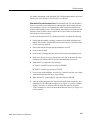
Figure 4–30: SCSI Hard Disk Format Utility Main Menu . . . . . . . . .
Figure 4–31: Configuration Utility Main Menu. . . . . . . . . . . . . . . . . .
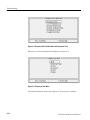
Figure 4–32: Hardware Configuration and Diagnostic
Results Display . . . . . . . . . . . . . . . . . . . . . . . . . . . . . . . . . . . . . . . . .
Figure 4–33: Factory Default Network Configuration Display . . . . .
Figure 4–34: Pod Connector of the P6461/E Probe . . . . . . . . . . . . . . .
Figure 4–35: Coaxial Probe Cable Header Pin Orientation . . . . . . . .
Figure 4–36: Removing a Coaxial Conductor (Wire) . . . . . . . . . . . . .
Figure 4–37: Snoopy Mode Example Request ARP Message . . . . . . .
Figure 4–38: Snoopy Mode Example Response ARP Message TCP/IP
Message . . . . . . . . . . . . . . . . . . . . . . . . . . . . . . . . . . . . . . . . . . . . . . .
Figure 4–39: Snoopy Mode Example Response TCP/IP Message . . .
Figure 4–40: 92LAN Snoopy Mode ICMP Example Message . . . . . .
Figure 5–1: DAS 9219/9220 Mainframe Cable Diagram . . . . . . . . . . .
Figure 5–2: DAS 9221 Mainframe Cable Diagram . . . . . . . . . . . . . . .
Figure 5–3: DAS System Bus Diagram . . . . . . . . . . . . . . . . . . . . . . . . .
DAS 9200 Technician’s Reference
4–58
4–59
4–60
4–61
4–62
4–63
4–64
4–65
4–66
4–67
4–68
4–72
4–98
4–99
4–101
4–113
4–116
4–118
4–134
4–135
4–136
4–137
5–2
5–3
5–4
vii
Table of Contents
Figure 5–4: DAS 9221 Controller Board Block Diagram . . . . . . . . . .
Figure 5–5: DAS 9219/9220 Controller Board Block Diagram . . . . . .
Figure 5–6: DAS 9219/9220 Memory Board Block Diagram . . . . . . .
Figure 5–7: DAS 92E9 Expansion Mainframe Cable Diagram . . . . .
Figure 5–8: 92A96 and 92C96 Module Functional Block Diagram . .
viii
5–6
5–9
5–11
5–14
5–21
DAS 9200 Technician’s Reference
Table of Contents
List of Tables
Table 1–1: Power for Master Mainframes . . . . . . . . . . . . . . . . . . . . . .
Table 1–2: Power for Expansion Mainframes . . . . . . . . . . . . . . . . . . .
Table 1–3: Power for DAS Cards (with Probes) . . . . . . . . . . . . . . . . .
Table 1–4: DAS Series Acquisition and Pattern Generation
Modules . . . . . . . . . . . . . . . . . . . . . . . . . . . . . . . . . . . . . . . . . . . . . . .
1–16
Table 3–1: Power-supply Connections . . . . . . . . . . . . . . . . . . . . . . . . .
3–17
Table 4–1: DAS 9221 Level 0 Diagnostics Messages . . . . . . . . . . . . . .
Table 4–2: DAS 9219/92200 Level 0 Diagnostics Messages . . . . . . . .
Table 4–3: Error Messages for DAS Mainframes . . . . . . . . . . . . . . . .
Table 4–4: LED Diagnostic Errors for DAS 9221 . . . . . . . . . . . . . . . .
Table 4–5: DAS 9219/9220 Controller Board LED
Diagnostic Errors . . . . . . . . . . . . . . . . . . . . . . . . . . . . . . . . . . . . . . .
Table 4–6: DAS 9219/9220 Memory Board
Diagnostic Errors . . . . . . . . . . . . . . . . . . . . . . . . . . . . . . . . . . . . . . .
Table 4–7: Previous Shutdown Field Messages . . . . . . . . . . . . . . . . . .
Table 4–8: DAS 9219/9220 Controller Board Diagnostic
Error Codes . . . . . . . . . . . . . . . . . . . . . . . . . . . . . . . . . . . . . . . . . . .
Table 4–9: DAS 9219/9220 8 Mbyte Memory Diagnostic
Error Codes . . . . . . . . . . . . . . . . . . . . . . . . . . . . . . . . . . . . . . . . . . .
Table 4–10: DAS 9221 Controller Board Diagnostic
Error Codes . . . . . . . . . . . . . . . . . . . . . . . . . . . . . . . . . . . . . . . . . . .
Table 4–11: 92A60/90/60D/90D Controller Diagnostic
Error Codes . . . . . . . . . . . . . . . . . . . . . . . . . . . . . . . . . . . . . . . . . . .
Table 4–12: 92A60/90/60D/90D Memory Diagnostic
Error Codes . . . . . . . . . . . . . . . . . . . . . . . . . . . . . . . . . . . . . . . . . . .
Table 4–13: 92A96 and 92C96 Diagnostic Error Codes . . . . . . . . . . .
Table 4–14: 92HS8/8E Diagnostic Error Codes . . . . . . . . . . . . . . . . . .
Table 4–15: 92S16/92SX109 Diagnostic Error Codes . . . . . . . . . . . . .
Table 4–16: 92S32/92SX118 Diagnostic Error Codes . . . . . . . . . . . . .
Table 4–17: 92A16/16E Diagnostic Error Codes . . . . . . . . . . . . . . . . .
Table 4–18: 92C01/02/03 Diagnostic Error Codes . . . . . . . . . . . . . . . .
Table 4–19: Diagnostic Bar Codes . . . . . . . . . . . . . . . . . . . . . . . . . . . .
Table 4–20: Power-On LAN Controller Tests . . . . . . . . . . . . . . . . . . .
Table 4–21: Shared-Memory Tests . . . . . . . . . . . . . . . . . . . . . . . . . . . .
Table 4–22: LAN Diagnostic Word . . . . . . . . . . . . . . . . . . . . . . . . . . . .
4–17
4–18
4–19
4–21
DAS 9200 Technician’s Reference
1–9
1–9
1–10
4–23
4–24
4–25
4–27
4–27
4–27
4–29
4–30
4–30
4–32
4–33
4–34
4–35
4–36
4–38
4–39
4–39
4–40
ix
Table of Contents
Table 4–23: 92LAN DTP Commands . . . . . . . . . . . . . . . . . . . . . . . . . .
Table 4–24: DTP Cable Wiring . . . . . . . . . . . . . . . . . . . . . . . . . . . . . . .
Table 4–25: Power-Supply Voltages . . . . . . . . . . . . . . . . . . . . . . . . . . .
Table 4–26: Test-Pad Signal Descriptions . . . . . . . . . . . . . . . . . . . . . .
Table 4–27: Baud Rate Dip Switches . . . . . . . . . . . . . . . . . . . . . . . . . .
Table 4–28: Hard Disk Byte vs. Sector . . . . . . . . . . . . . . . . . . . . . . . . .
Table 4–29: Default Swap Partition Size . . . . . . . . . . . . . . . . . . . . . . .
Table 4–30: Phase 1 File System Check Error Messages . . . . . . . . . .
Table 4–31: Phase 2 File System Check Error Messages . . . . . . . . . .
Table 4–32: Phase 3 File System Check Error Messages . . . . . . . . . .
Table 4–33: Phase 4 File System Check Error Messages . . . . . . . . . .
Table 4–34: Phase 5 File System Check Error Messages . . . . . . . . . .
Table 4–35: System Software vs Operating Modes . . . . . . . . . . . . . . .
Table 4–36: Probe-Cable Pin to Display-Channel Mapping . . . . . . .
Table 4–37: Terminal Factory Default Boot Parameters . . . . . . . . . .
Table 4–38: 92LAN Module Diagnostics . . . . . . . . . . . . . . . . . . . . . . .
x
4–41
4–43
4–44
4–44
4–46
4–78
4–82
4–86
4–87
4–88
4–88
4–90
4–102
4–116
4–124
4–131
DAS 9200 Technician’s Reference
General Safety Summary
Review the following safety precautions to avoid injury and prevent damage to
this product or any products connected to it.
Only qualified personnel should perform service procedures.
Injury Precautions
Use Proper Power Cord
To avoid fire hazard, use only the power cord specified for this product.
Ground the Product
This product is grounded through the grounding conductor of the power cord. To
avoid electric shock, the grounding conductor must be connected to earth
ground. Before making connections to the input or output terminals of the
product, ensure that the product is properly grounded.
Do Not Operate Without
Covers
To avoid electric shock or fire hazard, do not operate this product with covers or
panels removed.
Use Proper Fuse
To avoid fire hazard, use only the fuse type and rating specified for this product.
Do Not Operate in
Wet/Damp Conditions
Do Not Operate in
Explosive Atmosphere
Avoid Exposed Circuitry
To avoid electric shock, do not operate this product in wet or damp conditions.
To avoid injury or fire hazard, do not operate this product in an explosive
atmosphere.
To avoid injury, remove jewelry such as rings, watches, and other metallic
objects. Do not touch exposed connections and components when power is
present.
Product Damage Precautions
Use Proper Power Source
Do not operate this product from a power source that applies more than the
voltage specified.
DAS 9200 Technician’s Reference
xi
General Safety Summary
Use Proper Voltage
Setting
Provide Proper Ventilation
Do Not Operate With
Suspected Failures
Before applying power, ensure that the line selector is in the proper position for
the power source being used.
To prevent product overheating, provide proper ventilation.
If you suspect there is damage to this product, have it inspected by qualified
service personnel.
Safety Terms and Symbols
Terms in This Manual
These terms may appear in this manual:
WARNING. Warning statements identify conditions or practices that could result
in injury or loss of life.
CAUTION. Caution statements identify conditions or practices that could result in
damage to this product or other property.
Terms on the Product
These terms may appear on the product:
DANGER indicates an injury hazard immediately accessible as you read the
marking.
WARNING indicates an injury hazard not immediately accessible as you read the
marking.
CAUTION indicates a hazard to property including the product.
Symbols on the Product
The following symbols may appear on the product:
DANGER
High Voltage
xii
Protective Ground
(Earth) Terminal
ATTENTION
Refer to
Manual
Double
Insulated
DAS 9200 Technician’s Reference
General Safety Summary
Certifications and Compliances
CSA Certified Power
Cords
Compliances
CSA Certification includes the products and power cords appropriate for use in
the North America power network. All other power cords supplied are approved
for the country of use.
Consult the product specifications for IEC Installation Category, Pollution
Degree, and Safety Class.
DAS 9200 Technician’s Reference
xiii
General Safety Summary
xiv
DAS 9200 Technician’s Reference
Service Safety Summary
Only qualified personnel should perform service procedures. Read this Service
Safety Summary and the General Safety Summary before performing any service
procedures.
Do Not Service Alone
Do not perform internal service or adjustments of this product unless another
person capable of rendering first aid and resuscitation is present.
Disconnect Power
To avoid electric shock, disconnect the main power by means of the power cord
or, if provided, the power switch.
Use Caution When
Servicing the CRT
To avoid electric shock or injury, use extreme caution when handling the CRT.
Only qualified personnel familiar with CRT servicing procedures and precautions
should remove or install the CRT.
CRTs retain hazardous voltages for long periods of time after power is turned off.
Before attempting any servicing, discharge the CRT by shorting the anode to
chassis ground. When discharging the CRT, connect the discharge path to ground
and then the anode. Rough handling may cause the CRT to implode. Do not nick
or scratch the glass or subject it to undue pressure when removing or installing it.
When handling the CRT, wear safety goggles and heavy gloves for protection.
Use Care When Servicing
With Power On
Dangerous voltages or currents may exist in this product. Disconnect power,
remove battery (if applicable), and disconnect test leads before removing
protective panels, soldering, or replacing components.
To avoid electric shock, do not touch exposed connections.
X-Radiation
To avoid x-radiation exposure, do not modify or otherwise alter the high-voltage
circuitry or the CRT enclosure. X-ray emissions generated within this product
have been sufficiently shielded.
DAS 9200 Technician’s Reference
xv
Service Safety Summary
xvi
DAS 9200 Technician’s Reference
Preface
The Digital Analysis System (DAS) 9200 documentation package provides the
information necessary to install, operate, maintain, and service the DAS. DAS
documentation consists of:
H
This technician’s reference manual, which helps you isolate DAS problems
to the module level, replace that module, and recheck the status of the system
H
A verification and adjustment procedures manual, that allows a qualified
technician to verify specifications of the mainframe and modules
H
A system user manual, which includes a beginning user orientation, a
discussion of DAS system-level operation, and reference information such as
installation procedures, specifications, error messages, and a complete
glossary of terms
H
A series of module user manuals that cover each of the DAS acquisition,
pattern generation, and optional I/O modules
H
An on-line documentation package that includes a location-dependent
system of technical notes
H
A programmatic command language user manual that describes the set of
programmatic commands available for remotely controlling the DAS
H
A series of application software user manuals that describe the various
application software packages
H
A series of microprocessor-specific microprocessor support instructions
(designed to accompany the 92A60/90 Module User Manual and 92A96 &
92C96 Module User Manual) that describe the various microprocessor
support packages
H
A series of workbooks that teach concepts about DAS acquisition modules
and pattern generation modules
The DAS Technician’s Reference Manual is designed for use by qualified service
personnel. It contains information necessary to check, troubleshoot, and maintain
the DAS mainframe and all associated modules. Troubleshooting is primarily
based on internal power-up diagnostics. These diagnostics isolate problems to
the board (or module) level. Once the faulty board is identified, use the
instructions provided in this manual to remove and replace it. Replacing the
faulty board allows a minimum of downtime for the user. The board is later
repaired at the factory.
DAS 9200 Technician’s Reference
xvii
Preface
This manual contains the following sections:
xviii
H
Introduction to DAS Hardware. Provides a basic description of the DAS
system.
H
Maintenance. Provides information on how to keep the mainframe and
modules in good working condition. Line-voltage selection and lithium
battery replacement procedures are also given.
H
Disassembly/Reassembly Procedures. Gives instructions for disassembling
and reassembling the mainframe and probes.
H
Troubleshooting. Provides information on diagnostics and troubleshooting
practices.
H
General Circuit Functions. Gives an overview of circuit functions on
mainframe boards and instrument modules; bus descriptions are also given.
H
Replaceable Electrical Parts. Contains a list (including Tektronix part
numbers) of replaceable electrical parts for the DAS mainframe and
associated modules; some parts are only replaceable to the module/board
level.
H
Replaceable Mechanical Parts. Contains a list (including Tektronix part
numbers) of replaceable mechanical parts for the DAS mainframe and
associated modules.
DAS 9200 Technician’s Reference
Introduction to DAS Hardware
The Digital Analysis System (DAS) 9200 is a highly modular set of state-of-theart digital analysis tools. It includes the following items:
H
A mainframe
H
A color terminal
H
Acquisition and pattern-generation modules
H
Application software packages
H
Probes
By selecting and configuring these tools, you can customize your digital analysis
system for your applications.
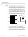
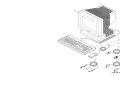
The DAS can be used either as a stand-alone digital analysis system or as an
intelligent peripheral device connected to a host computer or controller.
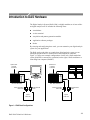
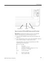
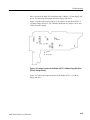
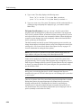
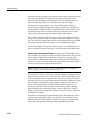
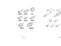
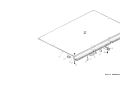
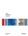
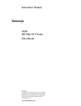
Figure 1–1 shows two example configurations. On the left, a DAS stand-alone
system (DASXP) is connected to a terminal; on the right, a DAS sends data to a
controlling host computer (DASNT).
Optional Host
Computer
Connection
Optional Host
Computer
Connection
Terminal
DAS 9200 Mainframe
Host Computer
DAS 9200 Mainframe
Acquisition Data
Probe
Pattern Generation
Data Probe
System
Under Test
Acquisition Data
Probe
Pattern Generation
Data Probe
System
Under Test
Figure 1–1: DAS Basic Configurations
DAS 9200 Technician’s Reference
1–1
Introduction to DAS Hardware
As a stand-alone system, the DAS can be connected to a Tektronix color
terminal, host computer, printer, or copier. The color terminal displays the
interactive menus. The host computer can be used to transfer acquisition,
stimulation, and instrument setup data to or from the DAS. Various types of
parallel and serial printers are supported to generate non-color (monochrome)
reproductions of display screens and acquisition and pattern-generation data.
Using the optional 92XTerm software (also known as DASNT systems), you can
operate the DAS from a window on a workstation. The interactive menus appear
in the workstation window and are controlled with the mouse and keyboard.
Communication between the DAS and the workstation is over a local area
network (LAN).
As a peripheral device remotely controlled by a host computer, the DAS supports
a Programmatic Command Language (PCL) that is an alternative to the keyboard
and menu interface. PCL commands let you start and stop acquisitions, manage
files, and report status and error information. Data can be processed either by the
DAS or the host computer; when the host computer processes data, the DAS is
the source of raw or partially processed data.
Mainframes and Terminals
The mainframes provide computing power, input and output features, and mass
storage for your modules. The mainframe provides enhanced computing power
due to its larger memory and faster CPU. The mainframes exist in the following
versions:
H
DAS 9221 with 16 Mbyte RAM on the Controller board, 100 Mbyte (or
greater) hard disk drive, and 1.4 Mbyte floppy disk drive
H
DAS 9220 with 8 Mbyte RAM on the Memory board, 40 Mbyte hard disk
drive, and 1.2 Mbyte floppy disk drive
H
DAS 9219 with 2 Mbyte RAM on the Memory board, 20 Mbyte hard disk
drive, and 400 Kbyte floppy disk drive (the DAS 9219 is no longer
available)
The DAS 92E9 is an Expansion mainframe with extra slots for additional modules.
1–2
DAS 9200 Technician’s Reference
Introduction to DAS Hardware
Terminals
The standard display device is a Tektronix color terminal with a detachable
keyboard. Earlier versions of the DAS used a 9200T or a 9201T monitor; newer
versions use an X terminal with a detachable keyboard and mouse. Interactive
menus, which are manipulated from the keyboard or mouse, allow you to define the
contents of the system, enter parameters and data, and control the outputs of the
instrument. These menus use color-coded command fields to show the available
selections.
You can power on and power off your mainframe and terminal from a 9200T or
9201T using the terminal power button. This feature is built into DAS 9221
mainframes; for DAS 9219/9220 mainframes, you must install an optional
one-button power-switch adapter.
The 9201T is a direct replacement for the 9200T, so references in this manual to
the 9201T also apply to the 9200T. However, references to the 4205 Service
Manual apply only to the 9201T; if you use a 9200T, refer instead to the 4105
Service Manual.
The X terminal requires a 92LANSE LAN (local area network) module installed
in the mainframe. You can use the X terminal only with the DAS/SE, DASXP, or
DASNT mainframes. For service information, refer to the TekXpress X Terminal
Service Manual.
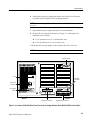
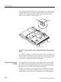
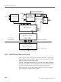
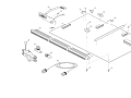
Mainframe Hardware
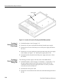
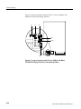
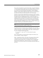
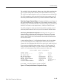
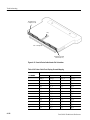
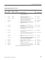
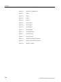
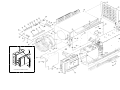
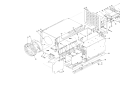
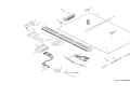
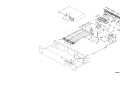
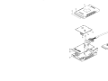
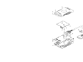
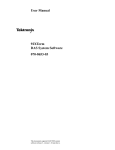
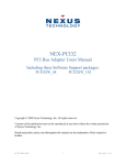
The mainframe shown in Figure 1–2 consists of the following major internal components:
H
Mechanical chassis
H
Controller board (with 16 Mbyte RAM for the DAS 9221)
H
Memory board with either 2 Mbyte or 8 Mbyte RAM (DAS 9219/9220)
H
Backplane board with 8 module slots
H
Hard disk drive
H
3.5 inch or 5.25 inch floppy disk drive
H
Three RS-232 ports
H
Power supply with a maximum output of 700 watts
DAS 9200 Technician’s Reference
1–3
Introduction to DAS Hardware
RS-232 Ports
(back of Mainframe)
Controller
Board (slot 0)
Power
Supply
Card Cage
Fan
Backplane
Board
Hard and
Floppy Disk
Drives
Figure 1–2: Master Mainframe Internal Components (Memory Board in Slot 1 for
DAS 9219/9220)
Mechanical Chassis. The chassis provides the mechanical connection and cooling
for all mainframe components and options. DAS modules reside in the card cage;
probes connect to the modules through openings in the rear of the chassis.
NOTE. To install, remove, or reposition any DAS module, you must remove the
mainframe top cover and card-cage door.
To disassemble major chassis components, refer to Disassembly/Reassembly
Procedures beginning on page 3–3.
Controller Board. The Controller board resides in slot 0 of the Master mainframe;
Expansion mainframes use an Expansion Slave board instead of a Controller
board. The Controller board provides the following resources:
H
1–4
DAS 9221 mainframes use a 68EC030 microprocessor with address
decoding for an asynchronous bus structure (32-bit address, 32-bit data).
DAS 9219/9220 mainframes use a 68010 microprocessor (24-bit address,
16-bit data).
DAS 9200 Technician’s Reference
Introduction to DAS Hardware
H
Nonvolatile RAM for storing interrupt routine addresses, previous shutdown
conditions, and pointers to other processes
H
64 Kbytes of boot ROM in DAS 9221 (32 Kbytes in DAS 9219/9220) for
power-up sequences and diagnostics
H
16 Mbytes of dynamic RAM (DAS 9221 only) with refresh circuitry
H
A communication interface between circuit boards, the hard disk drive, and
the floppy disk drive
H
Asynchronous time bases and other circuitry supporting the expansion of up
to four time-aligned mainframes
H
A clock/calendar with battery backup
H
Power-supply control for mainframe shutdown
Memory Board (DAS 9219 and DAS 9220). There are two different Memory boards:
the 2 Mbyte dynamic RAM board is standard with the DAS 9219, and the
8 Mbyte dynamic RAM board is standard with the DAS 9220. The 8 Mbyte
board is also available as a performance upgrade for the DAS 9219. Only one
Memory board can be installed in the Master mainframe, and it must reside in
slot 1; Expansion mainframes do not use a Memory board. (The DAS 9221 has
Memory-board functions resident on the Controller board.) The Memory board
provides the following resources:
H
2 Mbytes of dynamic RAM (standard with the DAS 9219) with refresh
circuitry for supporting system software, post-processing of acquired data,
and other calculations.
H
8 Mbytes of dynamic RAM (standard with the DAS 9220) with refresh
circuitry. The lower part of RAM supports system software and post-processing of acquired data. The upper part of RAM temporarily stores configuration and data files to improve the system response time.
H
Circuitry supporting the Memory Management Unit (MMU), for multiple
process control.
H
An interface to the Controller board, allowing access to the system RAM and
to the terminal, host, and auxiliary communication ports.
Backplane Board. This board provides the mechanical and electrical connections
between the Controller board, the Memory board (DAS 9219 and DAS 9220),
and the eight slots used for the acquisition and pattern generation modules.
Signals are carried on bus structures, some of which extend outside the Master
mainframe to Expansion mainframes.
DAS 9200 Technician’s Reference
1–5
Introduction to DAS Hardware
Hard and Floppy Disk Drives. The operating system software is installed on the
hard disk, along with other files (such as user-generated setups and reference
memories).
The DAS 9221 mainframes have been available with 100 Mbyte, 127 Mbyte,
170 Mbyte, and 270 Mbyte SCSI hard disk drives. The DAS 9220 mainframes
used 40 Mbyte and 80 Mbyte hard disk drives (ST506 interface), while the
DAS 9219 mainframes had 10 Mbyte and 20 Mbyte hard disk drives. To
determine the size of hard disk in your mainframe, refer to the Diagnostic menu.
An optional 80 Mbyte hard disk drive is available for DAS 9219/9220 mainframes. If data security or portability is a concern, you can order your mainframe
with a removable hard disk drive, so that setup and data files can be secured
overnight or easily transported to another DAS. An 80 Mbyte removable drive is
available for the DAS 9219/9220; a 127 Mbyte, 170 Mbyte, or 270 Mbyte
removable drive is available for the DAS 9221. (Other versions of the removable
hard disk drive were available for earlier versions of the mainframe.)
WARNING. The removable drive for the DAS 9221 (SCSI drive) is not interchangeable with the removable drives for the DAS 9219/9220 (ST506 interface
drives). If you install the wrong type of drive into your mainframe, you can
damage the drive.
Do not disconnect or remove the removable hard disk drive while the mainframe
is powered. Doing so will damage the hard disk or corrupt the file system.
The floppy disk drives are used for loading application software from floppy disk,
copying files for use on other mainframes, and making and restoring backup files.
Backup procedures with on-screen instructions are available. A light on the front of
the floppy disk drive indicates when a floppy disk is being accessed.
A 3.5 inch, 1.4 Mbyte floppy disk drive is standard in DAS 9221 mainframes
with System Software Release 3, Version 1.40 and higher. The floppy disk drive
is also available as an upgrade kit for older systems.
A 5.25 inch, 1.2 Mbyte floppy disk drive was available in earlier versions of the
DAS 9220 and DAS 9221 mainframes. This disk drive is available as an option
for the DAS 9219 mainframe. This drive reads floppy disks written in
360 Kbyte/400 Kbyte format; however, it cannot write to disks of this type. For
write operations, use only 96 TPI (tracks per inch), double-sided, high-density
floppy disks with this drive.
A 5.25 inch, 400 Kbyte floppy disk drive was standard in the DAS 9219
mainframe. This drive can read or write to floppy disks in 360 Kbyte/400 Kbyte
format only. Use only 48 TPI, double-sided, double-density floppy disks with
this drive; do not use 96 TPI high-density disks.
1–6
DAS 9200 Technician’s Reference
Introduction to DAS Hardware
RS-232 Ports. The DAS 9219/9220 mainframes have three 25-pin DCE RS-232
ports and the DAS 9221 mainframe has three 9-pin DCE RS-232 ports. Other
devices access these ports through openings on the rear panel. The three ports
have the following functions:
H
The terminal port connects the mainframe to a display device. Baud rates are
38400 (default), 19200, 9600, 4800, 2400, 1200, 600, 300, and 110.
H
The host port connects the mainframe to a host computer system with a
null-modem cable. Baud rates are 38400, 19200, 9600 (default), 4800, 2400,
1200, 600, 300, and 110.
H
The auxiliary port connects the mainframe to other RS-232-compatible
devices (for example, a printer). Baud rates are 38400, 19200,
9600 (default), 4800, 2400, 1200, 600, 300, and 110.
The host and auxiliary ports transmit eight data bits, no parity, and one stop bit. You
can configure the terminal and host port protocol using the Communications menu.
Optional Expansion and I/O Ports. The 92C01, 92C02, and 92C03 GPIB/Expansion modules are optional interface boards for the DAS. These modules function
as follows:
H
The 92C01 module provides a GPIB port for the mainframe. (It was
available for earlier versions of the mainframe.)
H
The 92C02 module provides a GPIB port and an interface to the DAS 92E9
Expansion mainframe.
H
The 92C03 module provides an interface only to the DAS 92E9 Expansion mainframe.
Master mainframes have direct memory access (DMA) capability; this feature is
not available in Expansion mainframes. Therefore, 92C01/02/03 modules must
be installed in slot 8 of the Master mainframe. The GPIB portion of the 92C01
and 92C02 modules does not work in the DAS 92E9 Expansion mainframe;
however, the 92C03 module and the expansion portion of the 92C02 module are
fully functional when installed in slot 8 of the Expansion mainframe. Therefore,
you should use the 92C03 module in Expansion mainframes.
LAN Interfaces. The 92LANSE and 92LAN Modules provide a LAN (local area
network) interface for the DAS mainframe. The 92LANSE module is standard in
a DAS 9221 mainframe used with the X terminals. These modules were optional
in other mainframes. The 92LANSE Module connects directly to the DAS 9221
Controller board and can only be used with DAS 9221 mainframes.
The 92LAN Module is no longer available. For information on the 92LAN
module, refer to the 92LAN User/Installation Manual.
DAS 9200 Technician’s Reference
1–7
Introduction to DAS Hardware
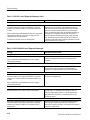
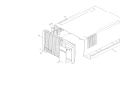
Power Supply. The power supply module consists of two boards that supply
power to all mainframe components. This supply can deliver up to 650 watts
from either a 115 V or 230 V AC power source (see Table 1–1 for Master
mainframes and Table 1–2 for Expansion mainframes).
WARNING. To change the line-voltage input of the power supply (between 115 V
and 230 V), refer to Maintenance beginning on page 2–1.
Mainframe Power
Requirements
The DAS mainframes support different numbers of acquisition and pattern-generation modules based on the type of power cord and power supply used with
each mainframe. The standard 12 A power cord should be used for Master
mainframes drawing less than 400 watts (12 A/115 V) and for Expansion
mainframes drawing less than 475 watts. When the module configuration in the
mainframe requires more power, a higher-current power-cord/power-supply
combination must be used (refer to Tables 1–1 and 1–2). If the module configuration in the Master mainframe requires more than 575 watts (650 watts in
Expansion mainframes), the DAS will automatically shut off.
NOTE. If you install the 15 A power cord (Option 1A), put the label supplied with
the power cord on the DAS back panel over the existing description that reads:
1900 VA MAX., FREQ. 48-63 Hz.
The power source must be capable of supplying the maximum line current
required for your system. A mainframe connected to a 115 V power source draws
a maximum continuous current of 15 A; the one-cycle surge current is 25 A
nominal. Therefore, a Master mainframe with three Expansion mainframes may
require a total line current of 60 A. (A mainframe connected to a 230 V power
source draws a maximum continuous current of 10 A, so a Master mainframe
with three Expansion mainframes may require a total line current of 40 A.)
When the DAS is connected to a 230 V power source, you must use a 230 V
power cord. The DAS draws no more than 10 A when operating at 230 V, but
when the DAS is connected to a 3-phase power source, the mainframe draws no
more than 8 A on any phase. The three-phase power cord is permanently attached
to the power supply. To upgrade your mainframe’s power supply with the
three-phase option, contact your Tektronix field service center.
1–8
DAS 9200 Technician’s Reference
Introduction to DAS Hardware
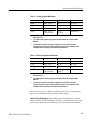
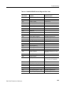
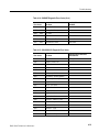
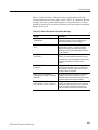
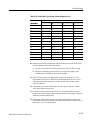
Table 1–1: Power for Master Mainframes
ÁÁÁÁÁÁÁ
ÁÁÁÁÁÁÁ
ÁÁÁÁÁÁ
ÁÁÁÁÁÁÁ
ÁÁÁÁÁÁÁ
ÁÁÁÁÁÁÁ
ÁÁÁÁÁÁ
ÁÁÁÁÁÁÁ
ÁÁÁÁÁÁÁ
ÁÁÁÁÁÁÁ
ÁÁÁÁÁÁ
ÁÁÁÁÁÁÁ
ÁÁÁÁÁÁÁ
ÁÁÁÁÁÁÁ
ÁÁÁÁÁÁ
ÁÁÁÁÁÁÁ
ÁÁÁÁÁÁÁ
ÁÁÁÁÁÁÁ
ÁÁÁÁÁÁ
ÁÁÁÁÁÁÁ
ÁÁÁÁÁÁÁ
ÁÁÁÁÁÁÁ
ÁÁÁÁÁÁ
ÁÁÁÁÁÁÁ
Watts
Voltage
Cord Option
Source
400 W
105 V – 127 V
Std.
115 V, 12 A
500 W
105 V – 127 V1
Opt. 1A
115 V, 15 A
575 W
200 V – 250 V
A1 – A5
230 V, 10 A
700 W2
200 V – 250 V
(phase-to-phase)
Opt. 1B
(3-phase)3
120/208 V, 8 A
1
Operation at a low line of 90 V is possible if the card-cage load is reduced to
425 watts or less.
2
The 700 W 3-phase power supply option was discontinued as of serial number
B061162.
3
The three-phase load is Y-connected. A maximum of 15 A at three times the
frequency may flow into the neutral conductor. A switch or circuit breaker at the
installation site is required by some international standards.
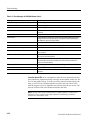
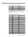
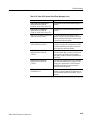
Table 1–2: Power for Expansion Mainframes
ÁÁÁÁÁÁÁ
ÁÁÁÁÁÁÁ
ÁÁÁÁÁÁ
ÁÁÁÁÁÁÁ
ÁÁÁÁÁÁÁ
ÁÁÁÁÁÁÁ
ÁÁÁÁÁÁ
ÁÁÁÁÁÁÁ
ÁÁÁÁÁÁÁ
ÁÁÁÁÁÁÁ
ÁÁÁÁÁÁ
ÁÁÁÁÁÁÁ
ÁÁÁÁÁÁÁ
ÁÁÁÁÁÁÁ
ÁÁÁÁÁÁ
ÁÁÁÁÁÁÁ
ÁÁÁÁÁÁÁ
ÁÁÁÁÁÁÁ
ÁÁÁÁÁÁ
ÁÁÁÁÁÁÁ
ÁÁÁÁÁÁÁ
ÁÁÁÁÁÁÁ
ÁÁÁÁÁÁ
ÁÁÁÁÁÁÁ
Watts
Voltage
Cord Option
Source
475 W
105 V – 127 V
Std.
115 V, 12 A
575 W
105 V – 127 V1
Opt. 1A
115 V, 15 A
650 W
200 V – 250 V
A1 – A5
220 V, 10 A
750 W2
200 V – 250 V
(phase-to-phase)
Opt. 1B
(3-phase)3
120/208 V, 8 A
1
Operation at a low line of 90 V is possible if the card-cage load is reduced to
425 watts or less.
2
The 750 W 3-phase power supply option was discontinued as of serial number
B061162.
3
The three-phase load is Y-connected. A maximum of 15 A at three times the
frequency may flow into the neutral conductor. A switch or circuit breaker at the
installation site is required by some international standards.
Refer to Selecting the Line Voltage and Replacing the Line Fuse beginning on
page 2–6 for instructions on how to change the line voltage.
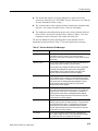
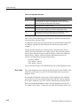
Module Power Requirements. Each combination of boards requires a different
amount of power from the mainframes. Therefore, you must select a power cord,
power supply, and power source that meets your system line-current demands.
DAS 9200 Technician’s Reference
1–9
Introduction to DAS Hardware
To determine the power cord and power source you need, check the message
displayed during power-on that shows the total wattage for the boards installed
in each mainframe. (The power-up message is erased when the system menus
display.) Calculate the total wattage required (from Table 1–3) and compare it
with the available power (from Tables 1–1 and 1–2). If the installed boards
require more power than is available from your current power cord and power
source, then you must upgrade your mainframe to meet those requirements.
NOTE. If you reconfigured the boards in your mainframe since the last powerdown or added boards to your system, check the power values in Tables 1–1,
1–2, and 1–3 to ensure that the total wattage required by the new configuration
can be supplied by your current mainframe power cord and power source.
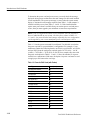
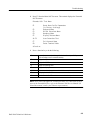
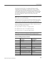
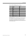
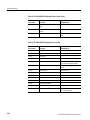
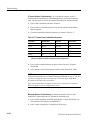
Table 1–3 lists the power consumed for each board. Use this table to calculate
the power required for your mainframe’s configuration. For example, if your
mainframe contains the following boards: one 92A16, two 92A16Es, one 92S16,
and one 92S32, then the total power required equals: 107 W (A16) + 166 W
(A16Es) + 78 W (S16) + 79 W (S32), or 430 W. Next, compare this value with
the power-cord options in Tables 1–1 and 1–2. Since the standard 12 A power
cord delivers a maximum of 400 watts, the Option 1A power cord must be used
to supply up to 500 watts to the card cage.
Table 1–3: Power for DAS Cards (with Probes)
ÁÁÁÁÁÁÁÁÁÁ
ÁÁÁÁÁÁÁ
ÁÁÁÁÁÁÁÁÁÁ
ÁÁÁÁÁÁÁ
ÁÁÁÁÁÁÁÁÁÁ
ÁÁÁÁÁÁÁ
ÁÁÁÁÁÁÁÁÁÁ
ÁÁÁÁÁÁÁ
ÁÁÁÁÁÁÁÁÁÁ
ÁÁÁÁÁÁÁ
ÁÁÁÁÁÁÁÁÁÁ
ÁÁÁÁÁÁÁ
ÁÁÁÁÁÁÁÁÁÁ
ÁÁÁÁÁÁÁ
ÁÁÁÁÁÁÁÁÁÁ
ÁÁÁÁÁÁÁ
ÁÁÁÁÁÁÁÁÁÁ
ÁÁÁÁÁÁÁ
ÁÁÁÁÁÁÁÁÁÁ
ÁÁÁÁÁÁÁ
ÁÁÁÁÁÁÁÁÁÁ
ÁÁÁÁÁÁÁ
ÁÁÁÁÁÁÁÁÁÁ
ÁÁÁÁÁÁÁ
ÁÁÁÁÁÁÁÁÁÁ
ÁÁÁÁÁÁÁ
ÁÁÁÁÁÁÁÁÁÁ
ÁÁÁÁÁÁÁ
ÁÁÁÁÁÁÁÁÁÁ
ÁÁÁÁÁÁÁ
ÁÁÁÁÁÁÁÁÁÁ
ÁÁÁÁÁÁÁ
ÁÁÁÁÁÁÁÁÁÁ
ÁÁÁÁÁÁÁ
ÁÁÁÁÁÁÁÁÁÁ
ÁÁÁÁÁÁÁ
Card Type
Power (watts)
92A16 Master Interface
107
92A16E Expander Interface
1–10
83
92A96/SD/UD
1501
92A96D/XD
140
92C96/D/XD/SD
1501
92A60 Controller
80
92A60/D Memory
50
92A90 Controller
80
92A90/D Memory
50
92S16
78
92S32
79
92SX109
78
92SX118
79
92C01
25
92C02
30
92C03
25
DAS 9200 Technician’s Reference
Introduction to DAS Hardware
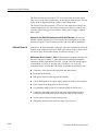
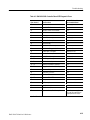
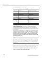
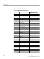
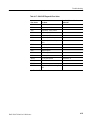
Table 1–3: Power for DAS Cards (with Probes) (Cont.)
ÁÁÁÁÁÁÁÁÁÁ
ÁÁÁÁÁÁÁ
ÁÁÁÁÁÁÁÁÁÁ
ÁÁÁÁÁÁÁ
ÁÁÁÁÁÁÁÁÁÁ
ÁÁÁÁÁÁÁ
ÁÁÁÁÁÁÁÁÁÁ
ÁÁÁÁÁÁÁ
ÁÁÁÁÁÁÁÁÁÁ
ÁÁÁÁÁÁÁ
ÁÁÁÁÁÁÁÁÁÁ
ÁÁÁÁÁÁÁ
ÁÁÁÁÁÁÁÁÁÁ
ÁÁÁÁÁÁÁ
ÁÁÁÁÁÁÁÁÁÁ
ÁÁÁÁÁÁÁ
Card Type
Power (watts)
92HS8 Master Interface
20
92HS8E Standard Interface
12
92LAN
25
92V64PM Pattern Master
64
92V64PE Pattern Expander
64
92V64E Error Memory
64
1
Acquisition Module power requirements reduced to
140 W max. effective SN B061162 and above
The DAS software checks your configuration at power on and warns you to use
the correct power source and power cord. The power supply and module cards
can be damaged if you try to operate the DAS in an illegal configuration. The
DAS 9221 Controller board contains a set of jumpers that identify the type of
power cord and power supply in the mainframe. If you change the power cord or
power supply, then you should relocate these jumpers to reflect the new configuration (refer to Jumper J8700 in Figure 4–29 on page 4–68). If the power requirements exceed safe limits, the system shuts down. For example, if you have five
92A96 Modules in one mainframe (700 W, which exceeds the power requirements), the DAS displays a warning message at power-up and then shuts down.
Power Cords. The mainframe has no main AC power switch, so the power cord
serves as the main-power disconnect. The power-cord connection for the Master
mainframe and Expansion mainframe is on the rear panel. The standard power
cord for the mainframe is rated at 12 A; optional power cords are available for
mainframe configurations requiring more power.
The mainframe uses a three-wire power cord with a three-contact plug for
connection to the power source and protective ground. The plug’s protectiveground connects to accessible metal parts of the mainframe.
WARNING. To protect against electrical shock, insert the power-cord plug into a
grounded power source receptacle.
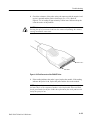
External Event Connections. The optional 92C02 and 92C03 modules provide a
set of pins that support external event I/O signals. For more information, refer to
Using the External Event I/O Pins in the DAS System User Manual.
DAS 9200 Technician’s Reference
1–11
Introduction to DAS Hardware
The External Event In pin accepts a TTL-level signal from an external source.
The received event can be monitored by (or can control) other modules. You can
set this up in the Signal Definition overlay (Cluster Setup menu).
The External Event Out pin passes a TTL-level event signal from a DAS to an
external component to use as an arming or triggering signal. For example, the
event-out signal can trigger an oscilloscope or stop, start, or trigger a separate
DAS system.
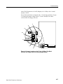
Discrete I/O Port (DAS 9221 Mainframes with 92LANSE Modules). The optional
92PORT software product allows you to monitor and send signals to a systemunder-test using the 37-pin D-connector on the rear of the Master mainframe.
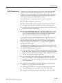
DAS with Option 04
An option to the DAS mainframe, Option 04, allows the mainframe to satisfy the
German electromagnetic interference (EMI) requirements. Refer to Replaceable
Mechanical Parts serial number history of Option 04 on page 7–24.
DAS Systems Prior to January 1, 1996. DAS mainframes equipped with Option 04
that were sold prior to January 1, 1996 satisfied the German electromagnetic
interference (EMI) requirements VDE 0871, Class B. This VDE option applied
to mainframes set for 230 V operation only; operation at 115 V exceeds
component ratings. A mainframe with Option 04 includes the following items:
1–12
H
Conductive elastic between the front panel and media mount
H
Rear-panel probe shields
H
EMI gasket material on the edges of the baseplate
H
Clip for holding the power supply tightly against the inside of the rear panel
H
Probe clamps for holding probes to the rear panel
H
Six grounding clamps for RS-232 connectors (DAS 9219/9220 only)
H
Conductive paint on the inside of the top cover and baseplate to make a
connection to the EMI gasket material along the edges of the baseplate
H
Screen material on the front panel and top cover
H
EMI gasket material on the inside-rear edge of the top cover
DAS 9200 Technician’s Reference
Introduction to DAS Hardware
Follow these precautionary guidelines when using an Option 04-equipped
mainframe:
H
Avoid scratching any surface coated with conductive paint.
H
Avoid bending or tearing gasket material along the edges of the baseplate
and snagging clothing on gasket material.
H
Avoid bending or snagging the EMI gasket material when installing or
removing boards from mainframe slots.
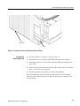
Remove only shields that correspond to probes or cables being attached, because
unnecessary removal of the shields increases EMI radiation. Remove a rear-panel
probe shield as follows:
1. Remove the two top screws.
2. Remove the two screws that attach the adjacent shield.
3. Remove the rear-panel probe shield.
4. Replace the screws attaching the adjacent shield.
To connect to the host port of a DAS 9219/9220 mainframe, you must remove
the corresponding port connector shield.
DAS Systems After January 1, 1996. Newer DAS mainframes with Option 04 meet
Directive 89/336/EEC for electromagnetic compatibility. Option 04 applies to
mainframes set for 230 V operation only; operation at 115 V exceeds component
ratings. A mainframe with Option 04 includes a 230 V line filter to eliminate or
reduce electromagnetic interference.
DAS 9200 Technician’s Reference
1–13
Introduction to DAS Hardware
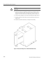
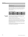
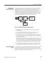
DAS 92E9 Expansion
Mainframe
The DAS 92E9 Expansion mainframe provides additional slot space for
acquisition and pattern generation modules. Up to three Expansion mainframes
can be added to the Master mainframe. A fully-expanded system (Master
mainframe with three Expansion mainframes) provides a total of 28 usable slots.
Expansion and Master mainframes use the same mechanical chassis, backplane,
and power supply. However, the Expansion mainframe does not contain a
Memory board, power switch, or disk drives. In an Expansion mainframe, an
Expansion Slave board replaces the Master mainframe’s Controller board.
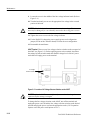
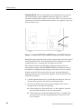
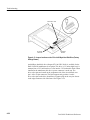
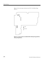
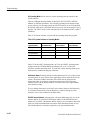
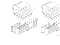
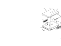
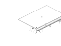
If you have one Expansion mainframe with the Master mainframe, you can place
it on top of the Master mainframe, as in Figure 1–3; the Master mainframe can
support the weight of only one Expansion mainframe. When using two or three
Expansion mainframes, all mainframes must be vertically rackmounted; the
Master mainframe must be positioned as the lowest mainframe in the rack. For
complete details on rackmounting, refer to the Option 05: Rackmount Installation Instructions document.
Acquisition Data Probe
Expansion
Mainframe
Master
Mainframe
Pattern Generation
Data Probe
System Under Test
Figure 1–3: DAS Master Mainframe Connected with One Expansion Mainframe
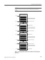
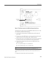
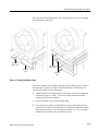
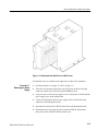
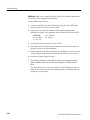
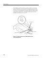
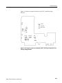
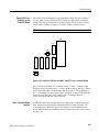
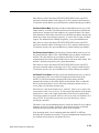
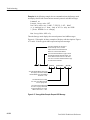
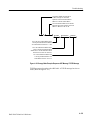
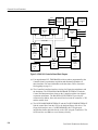
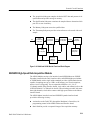
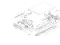
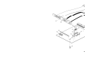
In a fully-expanded system (see Figure 1–4), the Master mainframe and
Expansion mainframes 1 and 2 require an Expansion board in slot 8 of each
mainframe. The Master mainframe uses either a 92C02 GPIB/Expansion module
or a 92C03 Expansion module to make the connection to the Expansion Slave
board installed in the next mainframe. Expansion mainframes 1 and 2 use a
92C03 module. Refer to Disassembly/Reassembly of the Mainframes beginning
on page 3–3 for module installation and removal instructions.
1–14
DAS 9200 Technician’s Reference
Introduction to DAS Hardware
NOTE. The system software numbers the DAS 92E9 Expansion Mainframe slots
from 9-35. You can use these slots, except the Expansion Slave board slot, for
modules.
Expansion Mainframe 3
Slot 35
8 slots for Acquisition and/or
Pattern Generation Modules
Slot 27
Expansion Slave Board
Expansion Cable
Expansion Mainframe 2
Slot 26
Expansion Board
7 slots for Acquisition and/or
Pattern Generation Modules
Slot 18
Expansion Slave Board
Expansion Cable
Expansion Mainframe 1
Expansion Board
Slot 17
7 slots for Acquisition and/or
Pattern Generation Modules
Expansion Slave Board
Slot 9
Expansion Cable
Master Mainframe
Slot 8
Expansion or Exp/GPIB
6 slots for Acquisition and/or
Pattern Generation Modules
Slot 0
Controller Board
Figure 1–4: Twenty-Eight Slots Available with One Master and Three Expansion
Mainframes
DAS 9200 Technician’s Reference
1–15
Introduction to DAS Hardware
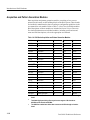
Acquisition and Pattern Generation Modules
Data acquisition and pattern generation modules, consisting of one or more
printed-circuit boards, are the building blocks of the DAS system. These boards
are installed in mainframe bus slots according to configuration guidelines in the
user manual for each module. Refer to Table 1–4 for a list of available modules.
Brief descriptions of these modules are included in General Circuit Functions.
For detailed information on individual modules, including specifications and
menu and field descriptions, refer to the appropriate user manual.
Table 1–4: DAS Series Acquisition and Pattern Generation Modules
ÁÁÁÁÁ
ÁÁÁÁÁÁÁÁ
ÁÁÁÁÁ
ÁÁÁÁÁ
ÁÁÁÁÁ
ÁÁÁÁÁ
ÁÁÁÁÁÁÁÁ
ÁÁÁÁÁ
ÁÁÁÁÁ
ÁÁÁÁÁ
ÁÁÁÁÁ
ÁÁÁÁÁÁÁÁ
ÁÁÁÁÁ
ÁÁÁÁÁ
ÁÁÁÁÁ
ÁÁÁÁÁ
ÁÁÁÁÁÁÁÁ
ÁÁÁÁÁ
ÁÁÁÁÁ
ÁÁÁÁÁ
ÁÁÁÁÁ
ÁÁÁÁÁÁÁÁ
ÁÁÁÁÁ
ÁÁÁÁÁ
ÁÁÁÁÁ
ÁÁÁÁÁ
ÁÁÁÁÁÁÁÁ
ÁÁÁÁÁ
ÁÁÁÁÁ
ÁÁÁÁÁ
ÁÁÁÁÁ
ÁÁÁÁÁÁÁÁ
ÁÁÁÁÁ
ÁÁÁÁÁ
ÁÁÁÁÁ
ÁÁÁÁÁ
ÁÁÁÁÁÁÁÁ
ÁÁÁÁÁ
ÁÁÁÁÁ
ÁÁÁÁÁ
ÁÁÁÁÁ
ÁÁÁÁÁÁÁÁ
ÁÁÁÁÁ
ÁÁÁÁÁ
ÁÁÁÁÁ
ÁÁÁÁÁ
ÁÁÁÁÁÁÁÁ
ÁÁÁÁÁ
ÁÁÁÁÁ
ÁÁÁÁÁ
ÁÁÁÁÁ
ÁÁÁÁÁÁÁÁ
ÁÁÁÁÁ
ÁÁÁÁÁ
ÁÁÁÁÁ
ÁÁÁÁÁ
ÁÁÁÁÁÁÁÁ
ÁÁÁÁÁ
ÁÁÁÁÁ
ÁÁÁÁÁ
ÁÁÁÁÁ
ÁÁÁÁÁÁÁÁ
ÁÁÁÁÁ
ÁÁÁÁÁ
ÁÁÁÁÁ
ÁÁÁÁÁ
ÁÁÁÁÁÁÁÁ
ÁÁÁÁÁ
ÁÁÁÁÁ
ÁÁÁÁÁ
ÁÁÁÁÁ
ÁÁÁÁÁÁÁÁ
ÁÁÁÁÁ
ÁÁÁÁÁ
ÁÁÁÁÁ
ÁÁÁÁÁ
ÁÁÁÁÁÁÁÁ
ÁÁÁÁÁ
ÁÁÁÁÁ
ÁÁÁÁÁ
ÁÁÁÁÁ
ÁÁÁÁÁÁÁÁ
ÁÁÁÁÁ
ÁÁÁÁÁ
ÁÁÁÁÁ
ÁÁÁÁÁ
ÁÁÁÁÁÁÁÁ
ÁÁÁÁÁ
ÁÁÁÁÁ
ÁÁÁÁÁ
ÁÁÁÁÁ
ÁÁÁÁÁÁÁÁ
ÁÁÁÁÁ
ÁÁÁÁÁ
ÁÁÁÁÁ
ÁÁÁÁÁ
ÁÁÁÁÁÁÁÁ
ÁÁÁÁÁ
ÁÁÁÁÁ
ÁÁÁÁÁ
ÁÁÁÁÁ
ÁÁÁÁÁÁÁÁ
ÁÁÁÁÁ
ÁÁÁÁÁ
ÁÁÁÁÁ
ÁÁÁÁÁ
ÁÁÁÁÁÁÁÁ
ÁÁÁÁÁ
ÁÁÁÁÁ
ÁÁÁÁÁ
ÁÁÁÁÁ
ÁÁÁÁÁÁÁÁ
ÁÁÁÁÁ
ÁÁÁÁÁ
ÁÁÁÁÁ
1–16
Module
Purpose
Channels
Depth
Speed
92A16
acquisition
16
4K
200 MHz
92A16E
acq. expander
16
4K
200 MHz
92A601
acquisition
60
32K
20 MHz
92A60D1
acquisition
60
128K
20 MHz
92A901
acquisition
90
32K
20 MHz
92A90D1
acquisition
90
128K
20 MHz
92A962
acquisition
96
8K
100 MHz
92A96D2
acquisition
96
32K
100 MHz
92A96XD2
acquisition
96
128K
100 MHz
92A96SD2
acquisition
96
512K
100 MHz
92A96UD2
acquisition
96
2M
100 MHz
92C96D2
acquisition
96
32K
100 MHz
92C96XD2
acquisition
96
128K
100 MHz
92C96SD2
acquisition
96
512K
100 MHz
92HS83
acquisition
8
8K
2 GHz
92HS8E3
acq. expander
8
8K
2 GHz
92S16
pattern generation
16
1K
50 MHz
92S32
pattern generation
32
8K
50 MHz
92SX109
pattern generation
9
2K
100 MHz
92SX118
pattern generation
18
16K
100 MHz
1
The 92A60/D and 92A90/D are both two-board sets; other modules consist of a single
board.
2
The 92A96 High-Speed timing offers asynchronous support of 48 channels at
200 MHz and 24 channels at 400 MHz.
3
The 92HS8 has a mainframe cabinet that connects to the DAS through an interface
board.
DAS 9200 Technician’s Reference
Introduction to DAS Hardware
You can combine modules functionally in menus. Combining acquisition
modules adds data-channel width (for example, combining 92A16 and 92A16E
boards). Combining pattern generation modules increases pattern memory depth
(for example, combining 92S16 and 92S32 boards). You can also group modules
to operate as an independently functioning unit (called a cluster); several clusters
can run simultaneously. For more information on grouping modules and clusters,
refer to the DAS System User Manual.
DAS 9200 Technician’s Reference
1–17
Introduction to DAS Hardware
1–18
DAS 9200 Technician’s Reference
Maintenance
This chapter explains how to keep your DAS mainframe, associated modules, and
terminal in good working condition. It also contains procedures on how to change
the line-voltage selection (between sources of 115 V and 230 V) and replace the
lithium battery on the Controller board of DAS 9219/9220 mainframes.
WARNING. Dangerous electric-shock hazards exist inside the mainframe. Be sure
to power down the mainframe and disconnect the power cord before removing
the cabinet. Only qualified service personnel should disassemble the mainframe.
CAUTION. When powering down the mainframe, wait 60 seconds before
disconnecting the power cord. This allows the mainframe to complete file-management procedures and move the hard disk head to a safe position.
Preventive Maintenance
Preventive maintenance consists of periodic cleaning. If dust accumulates on
components, it acts as an insulating blanket and prevents efficient heat dissipation. This condition can cause overheating and component breakdown. Periodic
cleaning reduces instrument breakdown and increases reliability.
You should clean the DAS mainframe and terminal as needed, based on the
operating environment.
Static Precautions
CAUTION. Many components within the mainframe are extremely susceptible to
static-discharge damage. Service the mainframe only in a static-free environment. Observe standard handling precautions for static-sensitive devices while
servicing the instrument. Always wear a grounded wrist strap, or equivalent,
while servicing the mainframe.
DAS 9200 Technician’s Reference
2–1
Maintenance
Observe the following precautions to avoid damage:
Cleaning Guidelines
H
Do not handle static-sensitive components on the boards.
H
Transport and store static-sensitive boards in their original containers or on
conductive foam. Label any package that contains static-sensitive assemblies.
H
Wear a wrist strap attached to the mainframe while handling the boards to
discharge the static voltage from your body.
H
If you need to temporarily set a board down, place it on the card cage to
protect it from damage by static voltage.
H
Do not allow anything capable of generating or holding a static charge on the
work surface.
H
Do not slide a board over any surface.
H
Avoid handling boards in areas that have a floor or work-surface covering
capable of generating a static charge.
H
When not in use, store boards in a static-free (conductive) package.
Use the following guidelines when cleaning the mainframe and modules:
CAUTION. Spray-wash dirty parts with a cleaning solution (as described in
Interior Cleaning, later in this section), THOROUGHLY RINSE with deionized
water, and IMMEDIATELY DRY with low air pressure.
When cleaning near unsealed electromechanical components, use as little
washing as possible. This prevents removing the lubricant from the components
and getting excess moisture into the contact areas of the switches. MOISTURE
WILL CAUSE CORROSION, which may degrade instrument performance.
DO NOT use a freon-based cleaner on the circuit boards. Freon will damage
aluminum capacitors.
DO NOT wash the Standby/On switch. Cover the switch during washing procedures.
DO NOT use fluorocarbon-based spray cleaners or silicon spray lubricants on
switches or switch contacts. These sprays may damage the circuit-board
material or plastic parts, and leave a dust-collecting residue. Use Tektronix
Contact Lubricant and Cleaner (part number 006-0442-00) as a lubricant.
To prevent damage from electrical arcing, completely dry all circuit boards,
switches, and board interface connectors. Do this by heating the board or switch
in an oven at 65° C (150° F) for 15 minutes before applying power.
2–2
DAS 9200 Technician’s Reference
Maintenance
Mainframe
The following paragraphs describe maintenance procedures for DAS mainframes.
Exterior Cleaning. Dust the exterior surfaces of the mainframe with a dry, lint-free
cloth or a soft-bristle brush. If dirt remains, use a cloth or swab dampened with a
75% isopropyl alcohol solution. A swab is also useful for cleaning in narrow spaces
around the controls. Do not use abrasive compounds on any part of the instrument.
CAUTION. To prevent getting moisture inside the instrument during external
cleaning, use only enough liquid to dampen the cloth or swab.
DO NOT use chemical cleaning agents; they may damage the plastics in the
instrument. In particular, avoid chemicals that contain benzene, toluene, xylene,
acetone, or similar solvents.
Interior Cleaning. Clean the interior every six months to keep dust from contaminating the disk drives. To access the mainframe’s interior, refer to the instructions in Disassembly/Reassembly Procedures.
Use a dry, low-velocity stream of air to clean the interior of the mainframe. A
soft-bristle brush is useful for cleaning around components. If a liquid must be
used for minor internal cleaning, use a 75% isopropyl alcohol solution and rinse
with deionized water.
Floppy Disk Drive. The floppy disk drive requires routine maintenance to operate
at maximum efficiency. The disks may be permanently damaged if dirt and dust
accumulate on the recording surfaces. To prevent damage, the disks should be
stored in the envelope and box provided, where they will not be exposed to dust
or dirt. In addition, the head should be cleaned periodically.
You will need the following materials for routine maintenance:
H
Vacuum cleaner
H
5.25 inch floppy-disk head-cleaning kit
The routine maintenance and cleaning schedules for the floppy disk drive are as
follows:
H
Clean the exterior (face) of the floppy disk drive monthly with a damp cloth
and a 75% isopropyl alcohol solution.
CAUTION. Do not allow moisture to enter the disk drive. When power is applied,
voltages may damage internal components.
DAS 9200 Technician’s Reference
2–3
Maintenance
H
Clean the head monthly. Use the instructions provided with the head-cleaning kit.
H
Clean the interior every six months with a soft-bristle brush and vacuum
cleaner.
If the disk drive is heavily used, or is used in a dirty environment, you should
clean the drive more frequently.
Hard Disk Drive. The hard disk drive requires no periodic maintenance.
Terminal and Keyboard
The following paragraphs describe maintenance procedures for the terminal
and keyboard.
Exterior Cleaning. Dust the exterior surfaces of the terminal and keyboard with a
dry, lint-free cloth or a soft-bristle brush. If dirt remains, use a cloth or swab
dampened with a 75% isopropyl alcohol solution. A swab is also useful for
cleaning in narrow spaces around the controls. Do not use abrasive compounds
on any part of these instruments.
CAUTION. To prevent getting moisture inside the instrument during external
cleaning, use only enough liquid to dampen the cloth or swab.
DO NOT use chemical cleaning agents; they may damage the plastics in the
instrument. In particular, avoid chemicals that contain benzene, toluene, xylene,
acetone, or similar solvents.
Terminal Screen. Clean the face of the display screen using a soft cloth dampened
with a solution of 75% isopropyl alcohol.
Keyboard. Use an artist’s soft brush to remove any dust or foreign matter between
the keypads.
Interior Cleaning. For procedures on disassembly and interior cleaning of the
9200T, refer to the 4105 Service Manual. For procedures on disassembly and
interior cleaning of the 9201T, refer to the 4205 Service Manual. For disassembly and interior cleaning procedures for the X terminals, refer to the TekXpress X
Terminal Series Service Manual. (These manuals are not part of the DAS
documentation package; to obtain a manual, contact your local Tektronix
representative.)
2–4
DAS 9200 Technician’s Reference
Maintenance
DAS Modules
The following paragraphs describe cleaning procedures for the DAS modules.
To clean the surface of a DAS module, use a dry, low-velocity stream of air. A
soft natural-bristle brush is useful for cleaning around components. To prevent
static damage to parts, use only a natural-bristle brush (a synthetic brush can
generate static electricity).
CAUTION. Do not use liquid cleaning agents when cleaning the modules.
92HS8/8E Cabinet
The following paragraphs describe cleaning procedures for the 92HS8 cabinet.
Exterior Cleaning. Dust the exterior surfaces of the 92HS8/8E cabinet with a dry,
lint-free cloth or a soft-bristle brush. If dirt remains, use a cloth or swab
dampened with a 75% isopropyl alcohol solution. A swab is also useful for
cleaning in narrow spaces around the controls. Do not use abrasive compounds
on any part of the cabinet.
CAUTION. To prevent getting moisture inside the cabinet during external
cleaning, use only enough liquid to dampen the cloth or swab.
DO NOT use chemical cleaning agents; they may damage the plastics in the
instrument. In particular, avoid chemicals that contain benzene, toluene, xylene,
acetone, or similar solvents.
Interior Cleaning. To access the cabinet’s interior, refer to the instructions in
Disassembly/Reassembly Procedures.
Use a dry, low-velocity stream of air to clean the interior of the instrument. A
soft natural-bristle brush is useful for cleaning around components.
CAUTION. Do not clean in areas near a 92HS8/8E hybrid IC or its associated
Hypcon assembly elastomer.
DAS 9200 Technician’s Reference
2–5
Maintenance
Corrective Maintenance
Corrective maintenance consists of inspecting the instrument for damage and
obtaining replacement parts. Periodic inspection reduces instrument breakdown.
This section also discusses procedures for changing the line-voltage selection
and replacing the lithium battery on the Controller board.
Inspection
Inspect the instrument for broken connections, frayed wires, poorly seated
components, leaking capacitors, damaged hardware, and heat-damaged components. Heat damaged parts usually indicate other circuit problems.
If you notice any of the above problems, inform your Tektronix field representative.
Obtaining Replacements
Obtain replaceable parts for your instrument from your local Tektronix Field
Office or representative.
Mechanical. Most of the mechanical parts in this instrument are manufactured by
Tektronix. Some parts are selected by Tektronix to satisfy particular requirements, or are manufactured to certain specifications for Tektronix. To determine
the Tektronix part number of a mechanical part, refer to Replaceable Mechanical
Parts beginning on page 7–1.
Electrical. Individual electrical components are not replaceable parts, except fuses
and the lithium battery on the DAS 9219/9220 Controller board. Instead, whole
assemblies are replaced (such as the 92A16 module, 92HS8 cabinet, or 92HS8
interface cable). The part numbers for the assemblies can be found in Replaceable
Electrical Parts. The power supply is replaceable as a unit only. The part number
can also be found in Replaceable Electrical Parts beginning on page 6–1.
Selecting the Line Voltage
and Replacing the Line
Fuse
DAS Mainframe. To change between the 115 V and 230 V line-voltage selections
on the mainframe, perform the following steps.
CAUTION. A power supply with Option 04 (VDE) should operate at 230 V only,
not at 115 V. Option 04 provides a line filter.
WARNING. Disassembly procedures should be performed only by qualified
service personnel. You may be exposed to dangerous electric-shock hazards if
you remove the cover. Before removing the cover, power down the mainframe,
wait 60 seconds, and then disconnect the power cord. This procedure allows the
power-down sequence to complete.
2–6
DAS 9200 Technician’s Reference
Maintenance
1. Perform steps 8, 9, 11, 12, and 13 of Procedure 7: Removing the Power
Supply beginning on page 3–15.
2. Remove the three screws holding the power supply frame together, as shown
in Figure 2–1.
Screws (3)
Figure 2–1: Location of Power Supply Frame Screws
3. Gently lower the side of the power supply to expose the inside of the
power supply.
4. Refer to Figure 2–2 to locate the line voltage selection jacks (J134, J136,
J137, J138, and J139) at the rear of the Primary board in the power supply.
DAS 9200 Technician’s Reference
2–7
Maintenance
Label
Jacks
Secondary Board
Primary Board
Figure 2–2: Location of Line Voltage Selection Jacks
5. Refer to Figure 2–3 to determine the current line selection.
W135
W135
J136
Primary Board
Secondary Board
J136
J134
J139
J138
J137
8–9
8–0
8–N
J164
J163
J162
115 VAC Operation
Primary Board
Secondary Board
J134
J139
J138
J137
8–9
8–0
8–N
J164
J163
J162
230 VAC Operation
Figure 2–3: Position of Line Voltage Selection Jacks for 115 V or 230 V Operation
NOTE. The numbers 8-9, 8-0, and 8-N in Figure 2–3 indicate the following
wire-color code (resistor color code standard):
H Wire 8-9 is a gray wire with a white stripe.
H Wire 8-0 is a gray wire with a black stripe.
H Wire 8-N is a gray wire with no stripe.
2–8
DAS 9200 Technician’s Reference
Maintenance
6. Change the selection by grasping the plastic boot of the wire with needlenose pliers and moving the wire to the appropriate jack.
NOTE. When installing W135 on J136 or J134, turn W135 180_to insert it on
the jack.
7. Reassemble the power supply and replace it in the mainframe.
8. Remove the fuse from the back panel (see Figure 2–4 ) and replace the
mainframe fuse as follows:
H
115 V operation uses a 15 A, medium blow fuse.
H
230 V operation uses a 10 A, slow blow fuse.
To determine the fuse part number, refer to Replaceable Electrical Parts.
NOTE. 230 V operation requires one of the power cord Options A1-A5.
GPIB Connector
Fuse
92LANSE
Connectors
Power Cord
Connection
Line Voltage
Indictor
Discrete I/O Connector
RS-232C Port Connectors
Figure 2–4: Location of DAS 9221 Back Panel Fuse and Line Voltage Indicator Knob (DAS 9219/9220 Look Similar)
DAS 9200 Technician’s Reference
2–9
Maintenance
9. Loosen the screw in the middle of the line-voltage indicator knob. (Refer to
Figure 2–4.)
10. Turn the knob until you can see the appropriate line voltage in the recessed
portion of the knob.
CAUTION. Check that the indicator shows the correct line voltage. The instrument may be damaged if it is accidentally connected to the wrong power source.
11. Tighten the screw to secure the line voltage indicator.
12. For the DAS 9221, change the power-supply/power-cord configuration
jumper (J8700 on the Controller board) to reflect the new configuration.
13. Reassemble the mainframe.
9200T Terminal. There are two line voltage selection switches on the rear panel of
the 9200T (see Figure 2–5). Before applying power to the terminal, check that
the settings of both switches match the nominal voltage level of the AC power
outlet that will supply power to the terminal.
AC Voltage
Selector Switches
Figure 2–5: Location of AC Voltage Selector Switches on the 9200T
CAUTION. After the 9200T is turned off, wait five seconds to discharge the
capacitors before turning it on again.
To change the line voltage selection on the 9200T, turn off the terminal and
unplug the power cord. Switch the line-voltage selection switches to the desired
position and plug the power cord into the appropriate outlet. (230 V operation
requires one of the power cord Options A1-A5.)
2–10
DAS 9200 Technician’s Reference
Maintenance
9201T Terminal. There is one line voltage selection switch on the rear panel of the
9201T. Before applying power, check that the setting of this switch matches the
nominal voltage level of the AC power outlet that will supply power to the
terminal.
CAUTION. After the 9201T is turned off, wait five seconds to discharge the
capacitors before turning it on again.
To change the line voltage selection on the 9201T, turn off the terminal and
unplug the power cord. Switch the line voltage selection switch to the desired
position and plug the power cord into the appropriate outlet. (230 V operation
requires one of the power-cord Options A1-A5.)
X Terminals. There are no line voltage selection for the X terminals. The
terminals automatically adjust to line voltages in the range of 90 to 260 VAC
with the frequency between 48 and 66 Hz. Only use a power cable with the
appropriate power source that is in good condition and complies with the local
certification standards.
92HS8/8E Cabinet. The line voltage selector switch, line fuse, and AC power
switch for the 92HS8 cabinet are located inside the right side panel of the cabinet
(when facing the front of the cabinet). (See Figure 2–6.) The AC power switch
should always be in the on position (switched towards the front of the cabinet).
The line-voltage indicator for the 92HS8 cabinet is located on the left side of the
back panel (see Figure 2–7). A black hex-head screw indicates which voltage
source the cabinet is set to use.
WARNING. Changing the position of the back panel screw does not change the
power supply voltage range. The position of this screw is only an indicator of the
voltage setting.
DAS 9200 Technician’s Reference
2–11
Maintenance
Voltage Selector
115 V or 230 V
Fuse
AC Power
Switch
Figure 2–6: Location of the Line Voltage Selector and Line Fuse Behind the 92HS8/8E Side Panel
2–12
DAS 9200 Technician’s Reference
Maintenance
Line Voltage
Indicator
Figure 2–7: Back Panel Location of the 92HS8 Line Voltage Indicator Screw
To change the line voltage selector on the 92HS8/8E cabinet between 115 V and
230 V operation, perform the following steps.
1. Power down the DAS mainframe and 92HS8 cabinets and disconnect all
power cords.
2. Facing the rear of the 92HS8 cabinet, remove the corner feet on the top and
bottom of the left side of the cabinet using a TORX screwdriver.
3. Slide the cabinet side out of its holding track to expose the power supply line
fuse and line-selector switch, located near the front of the instrument.
4. Change the line voltage selector, then remove the 92HS8 line fuse and
replace it as follows:
H
115 V operation requires a 5 A, fast blow fuse.
H
230 V operation requires a 2.5 A, fast blow fuse.
NOTE. 230 V operation requires one of the power-cord Options A1-A5.
To determine the part number of these fuses, refer to Replaceable Electrical
Parts.
5. Replace the side panel and corner feet on the cabinet.
DAS 9200 Technician’s Reference
2–13
Maintenance
6. Remove the line-voltage indicator screw on the back panel and position it to
indicate the power source being used.
Replacing the Battery on
the DAS 9219/9220
Controller Board
The DAS 9219 and DAS 9220 mainframes use a lithium backup battery on the
Controller board when there is no power to the mainframe (such as when the
power cord is not attached). This battery also provides backup power for the
clock/calendar feature displayed in the Diagnostic menu.
CAUTION. Battery replacement should be performed by a qualified technician.
NOTE. The DAS 9221 battery is built into the circuitry and has a 10-year life. To
replace this battery, a qualified service technician must replace a chip on the
Controller board.
If your mainframe is in constant use, you should check the battery yearly. If it is
not used for long periods, you should check the battery every six months.
Replace the backup battery if the voltage is near 2.6 volts, since the system
information stored in RAM may be lost if the voltage drops below this value.
To determine the condition of the battery, measure the battery voltage across the
battery (BT905 in Figure 2–8) with the line cord removed from the power
supply. When it becomes necessary to replace the backup battery on the
Controller board, use the following procedure:
CAUTION. After powering down the mainframe, wait 60 seconds before disconnecting the power cord to allow the mainframe to lock the head in the hard disk
drive and complete file-management procedures.
1. Remove the line cord from the power supply.
2. To provide temporary power to the Controller board circuits while replacing
the battery, connect an external +5 volt supply across C921 (shown in
Figure 2–8).
CAUTION. Before connecting the external power supply, observe the polarity of
the supply and the capacitor. Connect the minus (–) lead of the supply to the
grounded side of the capacitor.
2–14
DAS 9200 Technician’s Reference
Maintenance
Controller Board
U731
+ C921
–
U918
U925
U928
– BT905 +
Figure 2–8: Location of C921 on Mainframe Controller Board
3. Remove the battery (BT905 in Figure 2–8) by cutting the elastic band and
pulling the battery out of the holder.
WARNING. To avoid injury, observe proper procedures for handling and disposal of
lithium batteries. Improper handling may cause fire, explosion, or severe burns.
Don’t recharge, crush, disassemble, heat the battery above 100_ C (212_ F),
incinerate, or expose the contents of the battery to water. Dispose of the battery in
accordance with local, state, and national regulations. For further information,
refer to the Lithium Battery Disposal section following this procedure.
4. Place the new battery in position and push it into the holder, while observing
the correct polarity.
5. Disconnect the external +5 volt power supply.
6. Install a new elastic band around the battery by performing the following
substeps:
a. Perform steps 2, 7, and 8, of Procedure 8: Removing the Card Cage
beginning on page 3–18 in the Disassembly/Reassembly Procedures chapter.
b. Gently pull the card-cage assembly up from the nylon posts.
c. Insert the elastic band into the holes provided. Pull the elastic band
tightly, from the bottom, with needle-nose pliers.
d. Reinstall the card-cage assembly.
7. Check the condition of the battery by measuring the voltage across it. It
should measure approximately 3 volts.
DAS 9200 Technician’s Reference
2–15
Maintenance
Disposing the Lithium
Battery
2–16
You can safely dispose of small quantities of batteries (less than 20) with
ordinary garbage in a sanitary landfill; larger quantities must be sent by surface
transport to a Hazardous Waste Disposal Facility. The batteries should be
individually packaged to prevent shorting and packed in a sturdy container that is
clearly labeled “Lithium Batteries — DO NOT OPEN.”
DAS 9200 Technician’s Reference
Disassembly/Reassembly Procedures
This chapter describes the disassembly and reassembly procedures for the DAS
mainframes, 92HS8 cabinet, and acquisition and pattern generation module probes.
In the following procedures, directional terms (top, bottom, left, right, front, and
back) assume that your mainframe is in an upright position (with the bottom
down), and that you are facing the front of the mainframe. Reassembly procedures are the reverse of the disassembly procedures unless otherwise noted.
Figure 3–1 shows the DAS mainframe; use this figure to locate the major
components. The DAS 92E9 Expansion mainframe is very similar to the DAS.
In the disassembly procedures, differences between these mainframes are noted.
RS-232 Ports
(back of Mainframe)
Controller
Board (slot 0)
Power
Supply
Card Cage
Fan
Backplane
Board
Hard and
Floppy Disk
Drives
Figure 3–1: DAS Mainframe Internal Components (Memory Board in Slot 1 for
DAS 9219/9220)
In addition to the illustrations in this section, refer to Replaceable Mechanical
Parts for a detailed exploded view and parts list for the mainframes.
DAS 9200 Technician’s Reference
3–1
Disassembly/Reassembly Procedures
General Precautions
Observe the following precautions when performing any disassembly/reassembly
procedures.
CAUTION. After powering down the mainframe with the Standby/On switch, wait
60 seconds before disconnecting the power cord. This allows the mainframe to
lock the head in the hard disk drive to a safe position and complete file-management procedures.
H
DO NOT attempt any disassembly procedure with the power cord connected.
H
DO NOT operate a mainframe or 92HS8 cabinet with the cover removed to
prevent overheating.
H
DO NOT attempt mainframe disassembly procedures with probes installed
or RS-232 connections in place.
H
DO NOT place the mainframe on its front face. The front panel will not
support the weight of the mainframe.
Tools Required
The following list identifies the tools necessary for disassembly of the DAS
mainframes, 92HS8 cabinet, and probes. This is a complete list of tools; you will
need only the tools for your specific disassembly needs.
H
3
H
1
H
11 inch (shaft length) #2 POZIDRIV screwdriver (magnetic tip)
H
1
H
#1 POZIDRIV screwdriver
H
#1 Phillips screwdriver
H
Torque screwdriver with the following tips:
16 inch
4 inch
8
flexible shaft nutdriver
nutdriver
inch flat-blade screwdriver
1
inch slotted blade tip
1
nutdriver tip
8
4 inch
#1 Phillips tip
TORX-type magnetic tip (T-20)
3–2
DAS 9200 Technician’s Reference
Disassembly/Reassembly Procedures
H
#0 Phillips screwdriver
H
Small diagonal cutters
H
Two board ejector tools (located inside the mainframe front panel) (Tektronix part number 105-0985-00)
Disassembly/Reassembly of the Mainframes
The following procedures describe how to disassemble and reassemble the DAS
Master mainframe and DAS 92E9 Expansion mainframe. The user may
perform procedures 1 and 2. However, qualified service personnel must
perform the other procedures.
CAUTION. Only qualified service personnel should perform disassembly
procedures. Dangerous electric-shock hazards may be exposed when you remove
the mainframe cover. Power down the mainframe and wait 60 seconds before
disconnecting the power cord, so the power-down sequence completes.
Procedure 1:
Removing the Mainframe
Top Cover
To install or remove a module, you must first remove the mainframe’s top cover
and inner card-cage door. Use the following steps to remove the top cover.
1. Power down the mainframe.
CAUTION. After powering down the mainframe, wait 60 seconds before disconnecting the power cord. This allows the head in the hard disk drive to lock in a
safe position and the software to complete file-management procedures.
2. Disconnect the power cord.
3. Press the plastic latches on the left and right lower-rear sides of the cover and
lift the cover from the back (see Figure 3–2).
DAS 9200 Technician’s Reference
3–3
Disassembly/Reassembly Procedures
Press
Lift
Figure 3–2: Removing the Mainframe Top Cover
4. Tilt the cover off the front of the mainframe. Set the cover aside so its inner
surface will not be scratched.
Instructions for removing the card-cage door are listed in procedure 2.
3–4
DAS 9200 Technician’s Reference
Disassembly/Reassembly Procedures
Procedure 2:
Removing a Module From
the Card Cage
This procedure describes how to remove an acquisition or pattern generation
module from the mainframe card cage. It can also be used to remove other
boards (such as the Memory board in DAS 9219/9220 mainframes or GPIB/Expansion modules) that reside in reserved slots of the mainframe.
CAUTION. Many components within the mainframe are susceptible to
static-discharge damage. Follow the standard handling precautions for
static-sensitive devices under Static Precautions beginning on page 2–1 when
servicing this instrument.
1. Perform procedure 1 on page 3–3.
2. To remove the card-cage door, unscrew (counterclockwise) the fasteners on
the card-cage door (see Figure 3–3). Remove the door and set aside.
Ejector Tools
Fastener
Fastener
Card-Cage Door
Terminal Post Connector
Figure 3–3: Ejector Tools and Location of Card-Cage Door Fasteners
3. Disconnect the probes, GPIB, and LAN cables from the rear of the mainframe. For DAS 9219/9220 mainframes, disconnect the RS-232 connections.
4. Remove the connectors from the GPIB and LAN modules (if installed).
DAS 9200 Technician’s Reference
3–5
Disassembly/Reassembly Procedures
NOTE. When removing a 92A60 or 92A90 module, remove the 92A60/90 Memory
board before removing the buffer probe attached to the 92A60/90 Controller
board.
5. Insert the two board-ejector tools into the board you are removing, as shown
in Figure 3–3.
NOTE. Board-ejector tools are stored inside the front panel of the mainframe on
the left-hand side.
6. Pry the board from the backplane.
CAUTION. Pry with even force on both sides of the board to prevent bending the
backplane-alignment pins.
7. Grasp the sides of the board and pull it out of the card cage.
When installing modules, align the connection between the backplane and the
module before applying pressure; this prevents connector damage.
Procedure 2a:
Removing the 92LANSE
Module
1. Perform procedures 1 on page 3–3 and 2 on page 3–5 to remove all other
boards or modules from the mainframe.
2. Unscrew the five screws holding the 92LANSE module to the Controller
board.
3. Carefully lift the 92LANSE module and remove the three cables connected
to the module.
Procedure 3:
Removing the Front Panel
1. Perform procedure 1 on page 3–3.
2. Note the orientation of the connector(s) at the back of the Standby/On switch
and disconnect the connector(s) from the switch.
3. Place the mainframe so the bottom of the front panel hangs over the
workbench.
4. Press the release latches located underneath the front panel, as shown in
Figure 3–4. While pressing the latches, pull the front panel towards you.
5. Move the mainframe back onto the workbench.
3–6
DAS 9200 Technician’s Reference
Disassembly/Reassembly Procedures
Latch
(Underneath)
Latch
Figure 3–4: Location of Latches for Removing the Front Panel
Procedure 4:
Removing the Fan
1. Perform procedures 1 on page 3–3 and 3 on page 3–6.
2. Disconnect the two-wire power cable (W865) located on top of the fan.
3. Disconnect the three-wire sense cable connector (W866) located below the
power cable.
4. Remove the four screws that hold the fan to the card cage; they are located at
the 4, 6, 8, and 12 o’clock positions.
5. Pull the fan and fan cage towards you and off the mainframe.
When reinstalling the fan, do not allow the ribbon cables or wires to hang in
front of the fan. Torque the four screws that hold the fan to the card cage 5.0 to
6.0 inch pounds.
DAS 9200 Technician’s Reference
3–7
Disassembly/Reassembly Procedures
Procedure 5:
Removing the Media
Frame
This procedure describes how to remove the media frame from the DAS mainframe.
CAUTION. If your system has a removable media hard disk drive, remove it before
disassembly to prevent damage.
1. Perform procedures 1 on page 3–3 and 3 on page 3–6.
2. Remove the ribbon cables connected to the Controller board beneath the
card-cage fan. For DAS 9219 and DAS 9220 mainframes, remove the three
ribbon cables (W298, W398, and W698) connected to J298, J398, and J698 on
the Controller board. For DAS 9221 mainframes, remove the two ribbon cables
(W3900 and W6900) connected to J3900 and J6900 on the Controller board.
3. Using care not to cut the power-supply wires, cut the plastic tie that holds the
power-supply wires to the top of the media frame.
4. Remove the stabilizer bracket connecting the media frame to the power-supply frame.
5. Unscrew the four screws that hold the media frame to the mainframe
baseplate (see Figure 3–5).
6. Grasp the media frame with both hands and tilt it outward, then lift up and
remove. You may need to open the cable clamp located on the left side of
the media frame before you can move the media frame onto the adjacent
work surface.
7. Remove the ribbon cable W965 that connects the power supply to the media.
3–8
DAS 9200 Technician’s Reference
Disassembly/Reassembly Procedures
Stabilizer
Bracket
Screws (6)
Figure 3–5: Location of Screws for Removing the Media Frame
Procedure 6:
Removing the Disk Drives
From the Media Frame
This procedure describes how to remove both the hard disk and floppy disk drives
from your media frame. This procedure does not apply to Expansion mainframes.
1. Perform procedure 5 on page 3–8.
2. Disconnect the ribbon cable(s) from the drive being removed.
3. Remove the two screws (on top of the appropriate drive) from the media frame.
4. Gently turn the media frame on its side, to prevent damage, and remove the
two bottom screws.
5. Grasp the drive from the front and pull towards you to remove it from the
media frame.
Installation Hints for Floppy Disk Drives. The procedure for installing the floppy
disk drive is essentially the reverse of the disassembly procedure. When installing
the floppy disk drive, torque the metric screws from 5.0 to 7.0 inch pounds.
DAS 9200 Technician’s Reference
3–9
Disassembly/Reassembly Procedures
CAUTION. Some disk drives use metric screws, identified by their gold finish.
Make sure metric screws are used only into metric mounting holes to prevent
damaging the threads.
Installation Hints for Fixed-Media Hard Disk Drives. The procedure for installing
the fixed-media hard disk drive is essentially the reverse of the disassembly
procedure.
1. Attach the data and controller cables to the floppy disk drive and hard-disk
connectors. Figures 3–6 and 3–7 show the correct connector and cable
arrangements for the different mainframes.
2. Secure the ribbon cables in the self-adhesive retaining clamp.
3. Connect the power cable to both disk drives (power-cable connectors are
keyed to the connectors on the disk drives). Use between 7.5 and 10.0 inchpounds of torque to fasten the media frame.
CAUTION. Be careful not to pinch any power or ribbon cables when installing the
media frame.
4. Reconnect the cables to the mainframe Controller board, routing the
cables so they do not block the airflow from either the card-cage fan or the
power-supply fan. The ribbon cables must be folded neatly, as shown in
Figure 3–8 on page 3–13.
5. Secure the power-supply wires to the top of the media frame using a cable tie.
3–10
DAS 9200 Technician’s Reference
Disassembly/Reassembly Procedures
Floppy Disk Data
Cable (red line on top)
Hard Disk Data
Cables (red line
on top)
Floppy Disk Drive
Power connector
Hard Disk Power
Connector
Figure 3–6: Typical Cable Connections for Fixed-Mount Hard and Floppy Disk
Drives for DAS 9219 and DAS 9220 Mainframes
DAS 9200 Technician’s Reference
3–11
Disassembly/Reassembly Procedures
Floppy Disk
Data Cable (red
line on top)
Hard Disk Data
Cables (red line
on bottom)
Floppy Disk Drive
Power connector
Hard Disk Power
Connector
Figure 3–7: Typical Cable Connections for Fixed-Mount Hard and Floppy Disk
Drives For DAS 9221 Mainframes
Installation Hints For Removable-Media Hard Disk Drives. The procedure for
installing the removable-media hard disk drive is essentially the reverse of the
disassembly procedure.
CAUTION. DO NOT install a DAS 9221 removable SCSI disk drive into a
DAS 9219 or DAS 9220 mainframe that uses removable ST506 drives. Installing
the wrong type of drive into a system may result in damage to the hardware.
Refer to Hard and Floppy Disk Drive Switch and Jumper Positions in
Troubleshooting for descriptions of the drives.
1. Before installing the new media frame, test the fit of the removable hard disk
drive. (See Figures 3–9 on page 3–14 and 3–10 on page 3–15 for the
different mainframes.) The disk drive should fit snugly into place with only a
small amount of friction from the media frame.
3–12
DAS 9200 Technician’s Reference
Disassembly/Reassembly Procedures
After you are satisfied with the fit, remove the hard disk drive before installing
the media frame in the DAS.
Floppy Disk
Ribbon Cable
Floppy Disk
Ribbon Cable
Hard Disk
Cable
Hard Disk
Cable
Figure 3–8: Folding the Ribbon Cables
If you have a DAS 9221 mainframe, fold the cables as shown in the left side of
the illustration. If you have a DAS 9219/9220 mainframe, fold the cables as
shown on the right side of the illustration.
2. Attach the data and controller cables to the floppy disk drive and hard-disk
connectors. Figures 3–6 and 3–7 show the correct connector and cable
arrangements for each mainframe.
3. Secure the ribbon cables in the retaining clamp.
4. Connect the power cable to both disk drives (power-cable connectors are
keyed to the connectors on the disk drives). Install the media frame into the
DAS, gently forcing it as far to the right as possible. Use 7.5 to 10.0 inchpounds of torque to fasten the media frame in place.
DAS 9200 Technician’s Reference
3–13
Disassembly/Reassembly Procedures
CAUTION. Be careful not to pinch any power or ribbon cables when installing the
media frame.
5. Reconnect the cables to the mainframe Controller board, routing the cables so
that they do not block the airflow from either the card-cage fan or the powersupply fan. The ribbon cables must be folded neatly, as shown in Figure 3–8.
6. Secure the power-supply wires to the top of the media frame using a cable tie.
7. Install the stabilizer bracket that secures the media frame to the powersupply frame.
8. Install the removable media after you complete all reassembly.
Figure 3–9: Removable 20 Mbyte Drive in DAS 9219/9220 Media Frame
3–14
DAS 9200 Technician’s Reference
Disassembly/Reassembly Procedures
Figure 3–10: Removable Hard Disk Drive in a Media Frame
The hard disk drive is installed on the right side in a DAS 9221 mainframe.
Procedure 7:
Removing the Power
Supply
1. Perform procedures 1 on page 3–3 and 3 on page 3–6.
2. Trace the wires from the front of the power supply to the three front-edge
connectors (J690, J590, and J390) on the Backplane board.
3. Using care not to cut the power-supply wires, cut the plastic tie that holds the
power-supply wires to the media frame.
4. Unscrew and disconnect the 21 power-supply wires from the three edge
connectors on the Backplane board.
5. Disconnect the ribbon cable (W290) from J290 on the Backplane board.
6. Disconnect the two-prong power cable connector (W865) and the threeprong sense cable connector (W866) from the fan.
DAS 9200 Technician’s Reference
3–15
Disassembly/Reassembly Procedures
NOTE. Remove the media frame before removing the power supply. It is not
necessary to remove the cables connected to the media for this procedure.
7. Unscrew the four screws that hold the media frame to the mainframe
baseplate (see Figure 3–5 on page 3–9).
8. Remove the stabilizer bracket connecting the media frame to the power-supply frame.
9. Remove the bracket connecting the power-supply frame to the card cage.
10. Grasp the media frame with both hands and tilt it outward, then lift up and
turn 90° to remove.
11. Remove the ribbon cable (W965) that connects the power supply to the media.
12. Unscrew the two bottom-front and two top-rear screws of the power-supply
frame from the mainframe. (See Figure 3–11.)
Screws (5)
Figure 3–11: Location of Screws for Removing the Mainframe Power Supply
CAUTION. Do not bend the pins on the back of the Backplane board when
removing or installing the power supply.
3–16
DAS 9200 Technician’s Reference
Disassembly/Reassembly Procedures
13. Slide the power supply toward the front of the mainframe, tilt it outward,
then lift the power supply out of the mainframe.
Refer to Table 3–1 when reconnecting the power-supply wires to the Backplane board.
Table 3–1: Power-supply Connections
ÁÁÁÁÁÁÁ
ÁÁÁÁÁÁÁ
ÁÁÁÁÁÁ
ÁÁÁÁÁÁÁ
ÁÁÁÁÁÁÁ
ÁÁÁÁÁÁÁ
ÁÁÁÁÁÁ
ÁÁÁÁÁÁÁ
ÁÁÁÁÁÁÁ
ÁÁÁÁÁÁÁ
ÁÁÁÁÁÁ
ÁÁÁÁÁÁÁ
ÁÁÁÁÁÁÁ
ÁÁÁÁÁÁÁ
ÁÁÁÁÁÁ
ÁÁÁÁÁÁÁ
ÁÁÁÁÁÁÁ
ÁÁÁÁÁÁÁ
ÁÁÁÁÁÁ
ÁÁÁÁÁÁÁ
ÁÁÁÁÁÁÁ
ÁÁÁÁÁÁÁ
ÁÁÁÁÁÁ
ÁÁÁÁÁÁÁ
ÁÁÁÁÁÁÁ
ÁÁÁÁÁÁÁ
ÁÁÁÁÁÁ
ÁÁÁÁÁÁÁ
Connector
Connector Slot #
Wire Color
Voltage
J690
1, 2
red
+17.5 V
J690
3, 4
violet
–17.5 V
J690
5–7
yellow
+3V
J590
1–7
any white1
+5V
1–7
any black2
GND
J390
1
All white wires are +5 V; connect these wires to any slot.
2
All black wires are ground; connect these wires to any slot.
CAUTION. When reconnecting cables, align ribbon cable W290 with J290 on the
Backplane board. If the connectors are offset, the power supply may be damaged.
When reinstalling the power-supply frame into the mainframe, perform the
following procedure:
1. Press the power-supply frame against the rear of the mainframe; check that
there is not a gap between the two frames.
2. Screw the two bottom-front screws of the power-supply frame to the
mainframe; apply between 3.5 and 4.0 inch-pounds of torque to the screws.
3. Screw the two top-rear screws of the power-supply frame to the mainframe;
apply between 3.5 and 4.0 inch-pounds of torque to the screws.
4. Check that the cables do not block the fans.
These steps maximize the air flow between the power-supply frame and the
media frame and reduce EMI radiation.
DAS 9200 Technician’s Reference
3–17
Disassembly/Reassembly Procedures
Procedure 8:
Removing the Card Cage
NOTE. You must remove the card cage from the mainframe before removing the
Controller board and the backplane.
1. Perform procedure 1 on page 3–3, procedures 2 and 2a on page 3–6, and
procedure 3 on page 3–6.
2. Disconnect the connectors to the GPIB, 92LAN, or 92LANSE boards. For
DAS 9221 mainframes, disconnect the three internal RS-232 cables from the
Controller board.
3. Remove the stabilizer bracket connecting the power-supply frame to the
card cage.
4. Disconnect the power cable connector (W865) and the sense cable connector
(W866) from the fan.
5. Disconnect W290 from J290 on the Backplane board.
6. Disconnect the ribbon cables located below the fan.
7. Unscrew and remove the 21 power-supply wires from the three connectors
on the Backplane board.
8. Remove the four screws from the back panel, as shown in Figure 3–12.
Screws (4)
Figure 3–12: Back Panel Screw Locations for Removing the Card Cage
3–18
DAS 9200 Technician’s Reference
Disassembly/Reassembly Procedures
9. Remove the two bottom-front screws, as shown in Figure 3–13.
Screws (2)
Figure 3–13: Bottom-front Screw Locations for Removing the Card Cage
10. Pull the card cage up from the nylon posts in the baseplate, then forward. Be
careful not to damage the internal RS-232 cables in the DAS 9221.
NOTE. You may need to pinch together the nylon supports on the Controller
board to separate it from the baseplate of the mechanical chassis.
When reconnecting the power-supply wires, torque the screws on the connector
from 3.5 to 4.0 inch-pounds. Align each nylon support with its mounting hole
before pressing the Controller board onto the baseplate.
DAS 9200 Technician’s Reference
3–19
Disassembly/Reassembly Procedures
Procedure 9:
Removing the Controller
Board
Preform the following procedure to remove the Controller board from the
master mainframe.
CAUTION. Many components within the mainframe are extremely susceptible to
static-discharge damage. Follow the standard handling precautions for
static-sensitive devices in Maintenance when servicing this instrument.
1. Perform procedure 1 on page 3–3, procedure 2 on page 3–5, procedure 3
on page 3–6, and procedure 8 on page 3–18.
2. Place the card cage upside down, so the bottom of the Controller board
faces up.
3. Remove the seven screws holding the Controller board to the card-cage
assembly.
4. Carefully push the Controller board from the backplane connection with one
hand, while holding the card cage with the other hand.
When reinstalling the Controller board, check that its connections to the backplane
are fully mated. Remember to reconnect any cables that were disconnected during
disassembly, such as the RS-232 cables in the DAS 9221 mainframe.
Procedure 10:
Removing and
Disassembling the
Expansion Cable
(DAS 92E9 only)
The first part of this procedure explains how to remove the expansion cable from
the mainframe.
1. With the power cord disconnected, perform procedure 1 on page 3–3.
2. Using procedure 2 on page 3–5, remove the boards from slots 1 and 2 to
access the Expansion Slave board.
3. Note the orientation and location of the connectors, then unplug the six cables
of the expansion-cable assembly. Refer to the cabling diagram for the
DAS 92E9 Expansion mainframe (Figure 5–7 on page 5–14) during
reassembly.
4. At the rear of the mainframe, remove the three screws from the top of the
strain-relief bracket; they hold together the two parts of the bracket for the
expansion-cable assembly. Then remove the fourth screw that holds the
strain-relief bracket to the mainframe back panel.
5. Note the orientation of the strain-relief bracket components, then remove them.
Remove the expansion-cable assembly from the Expansion mainframe.
6. To remove the end of the expansion-cable assembly that is connected to a
92C02/03 module, remove the two screws holding the expansion-cable
assembly to the DAS L-shaped retaining bracket.
3–20
DAS 9200 Technician’s Reference
Disassembly/Reassembly Procedures
The remaining steps describe how to disassemble the expansion-cable assembly.
7. Remove the three screws from the top of the expansion-cable assembly.
8. Remove the top cover to access the cables and board within the housing.
9. To remove the bottom cover, turn the housing face down and remove two
screws. (For reassembly, separate these smaller-size screws from the others.)
10. To remove the expansion-cable board from the housing, turn the housing
face up and remove the two screws holding the board to the bottom cover.
Tip the board up on one side and remove it from the housing, being careful
not to damage any cables.
Procedure 11:
Removing the Expansion
Slave Board (DAS 92E9
only)
The Expansion mainframes do not have a Controller board; instead, they have an
Expansion Slave board. Perform the following procedure for removing the
Expansion Slave board from the Expansion mainframe.
CAUTION. Many components within the mainframe are extremely susceptible to
static-discharge damage. Follow the standard handling precautions for
static-sensitive devices in Maintenance when servicing this instrument.
1. Perform procedure 1 on page 3–3, procedure 2 on page 3–5, procedure 3
on page 3–6, and procedure 10 on page 3–20.
NOTE. You may need to pinch together the nylon supports on the Expansion
Slave board to separate it from the bottom cover of the mechanical chassis.
2. Perform procedure 8 on page 3–18 to remove the card cage from the
mainframe. Place the card cage upside down, so the bottom of the Expansion
Slave board faces up.
3. Remove the seven screws holding the Expansion Slave board to the
card-cage assembly.
4. Carefully push the Expansion Slave board from the backplane connection
with one hand, while holding the card cage with the other hand.
When reinstalling the Expansion Slave board, check that its connector to the
backplane are fully mated. Check that all cables are connected as in the
DAS 92E9 cabling diagram (see Figure 5–7 on page 5–14).
DAS 9200 Technician’s Reference
3–21
Disassembly/Reassembly Procedures
Procedure 12:
Removing the Backplane
1. Perform procedure 1 on page 3–3, procedure 2 on page 3–5, procedure 3
on page 3–6, procedure 8 on page 3–18, and procedure 9 on page 3–20.
2. Place the left side of the card-cage assembly on the work surface.
3. Remove the five screws holding the Backplane board to the card cage.
4. Remove the plastic shield from the front of the Back plane board.
5. Separate the connection between the Backplane board and the Controller
board and then lift the Backplane board off the card-cage assembly.
When reconnecting the power-supply wires to the Backplane board, refer to
Table 3–1 on page 3–17. The screws must be torqued between 3.5 and 4.0 inchpounds.
Disassembly/Reassembly of the 92HS8 Cabinet
The following procedures describe the partial disassembly of the 92HS8 cabinet,
such as:
H
Removing the 92HS8 top, bottom, and side covers
H
Elevating the Memory board to access the Acquisition board
H
Removing the power supply and cooling fans
H
Replacing 92HS8 probes connected to the cabinet
Reassembly procedures, unless otherwise noted, are the reverse of the disassembly procedures.
The procedure for removing a 92HS8 Interface board from the DAS is similar to
removing any DAS module.
WARNING. The interior of the 92HS8 cabinet contains hazardous voltages.
Before removing the covers, power down the unit and disconnect the AC power
cord from the rear of the cabinet.
CAUTION. When reassembling the 92HS8, fold the cables to maximize the flow of
cooling air over the hybrids. Restricted air flow may cause the hybrids to
overheat.
3–22
DAS 9200 Technician’s Reference
Disassembly/Reassembly Procedures
Procedure 1:
Removing the 92HS8
Cabinet Covers
This procedure describes how to remove the cabinet top, bottom, and two side
covers. To remove any cover, you will need a screwdriver with a TORX-type tip.
NOTE. Operating the cabinet for extended periods without covers may cause the
instrument to overheat.
1. Disconnect the power cord from the 92HS8 cabinet.
2. Check that all cabling does not interfere with the cover being removed.
3. Remove the top cover by removing the two top corner feet at the rear of the
cabinet. Then slide the top cover to the rear and remove it from the cabinet.
4. Remove the bottom cover by removing the two bottom corner feet at the rear
of the cabinet and sliding the bottom cover to the rear of the cabinet.
5. Remove a side cover by removing the top and bottom corner feet from the
rear of the cabinet for the side (left or right) being removed. Slide the side
cover to the rear of the cabinet.
Procedure 2:
Elevating the 92HS8
Memory Board
Perform this procedure to access the components under the Memory board.
1. Perform Procedure 1.
2. Remove the seven screws holding the board in place (see Figure 3–14).
3. Swing the Memory board to the upright position, since the board is secured
to the cabinet by a hinge on the left side of the cabinet.
NOTE. You may need to prop the board in the upright position.
DAS 9200 Technician’s Reference
3–23
Disassembly/Reassembly Procedures
Memory Board
Screws (7)
Figure 3–14: Location of Screws for Elevating the 92HS8 Memory Board
Procedure 3:
Removing the 92HS8
Power Supply
1. Perform Procedures 1 and 2 on page 3–23.
2. Remove the AC power cord (inside the cabinet) from the power supply.
3. Remove the two screws from the top cover of the power supply and remove
the cover.
4. Remove the six screws and the two spacer posts that secure the power supply
to the cabinet (see Figure 3–15). Tip the power supply onto its side.
5. Unsolder the cables from the back of the power supply and remove it from
the cabinet.
Procedure 4:
Removing the 92HS8
Cooling Fans
The following procedure applies to the three fans in the 92HS8 cabinet.
1. Perform Procedures 1 and 2 on page 3–23 and steps 1-3 of procedure 3. Tip
the power supply to gain access to the necessary screws. Note: Do not
unsolder the wires to the power supply and remove it, unless you cannot
access the screws for fan removal.
2. Disconnect the fan’s power cable.
3. Remove the screws and nuts from each corner of the fan housing and remove
the fan.
3–24
DAS 9200 Technician’s Reference
Disassembly/Reassembly Procedures
Procedure 5:
Replacing 92HS8 Probes
Probes must be installed from the inside of the instrument and pulled through to
the outside. Use the following procedure when removing and installing probes.
1. Remove the cabinet’s top cover and lift the Memory board, using procedures
1 and 2 on page 3–23.
2. To remove a probe, remove the probe ground clamp and carefully disconnect
the leads from the SMB and harmonica connectors on the Acquisition board.
While compressing the probe’s boot, pull the probe through the back panel to
the inside of the cabinet.
3. Feed the replacement probe through the back panel from the inside of the
cabinet. Check that the probe’s strain relief is correctly seated in the back panel.
4. Dress the probe wires carefully so that the shields do not contact the chassis
(probe shields are +5 volts).
5. Check that the red coax connects to the +SMB connector and the black coax
connects to the -SMB connector.
6. Check that pin 1 on the three-wide harmonica connector is correctly oriented
with pin 1 on the socket.
7. After probe replacement, recalibrate the 92HS8 using the deskew procedures
described in the 92HS8/8E Module User Manual.
DAS 9200 Technician’s Reference
3–25
Disassembly/Reassembly Procedures
Fan
Heat Sink
Power Supply Cover
Screws
Screw
Screw
Voltage Selector
Screw
Power Cord Plug
Power Supply Board
AC Power Switch
Screw
Screw
Posts (2)
Screw
Figure 3–15: Location of Screws for Removing the 92HS8 Power Supply
Disassembly/Reassembly of Probes
The circuit-board assemblies in each DAS probe are replaceable. The following
procedures describe how to disassemble and reassemble each probe, so you can
replace the assemblies.
CAUTION. Static discharge may damage the probe semiconductors. Follow the
standard handling precautions for static-sensitive devices under Static Precautions on page 2–1 when servicing the probes.
3–26
DAS 9200 Technician’s Reference
Disassembly/Reassembly Procedures
P6461/E Data Acquisition
Probe
1. Press the latches located on the sides of the P6461 probe.
2. Grasp the top and bottom halves of the probe and pull apart.
3. Remove the static shield.
4. If you need to remove one or more of the podlets, grasp the podlet by the
base, close to the pins, and pull the podlet from the sockets on the board.
5. Disconnect the cable from the board by grasping the pin connector from each
side and pulling the connection apart.
6. Remove the board from the case.
Reassembly of the probe is the reverse of the disassembly procedure. When
reassembling the probe, start with the labeled half of the case facing down. Then,
insert the board.
P6460 Data Acquisition
Probe
1. Unscrew the screws in each corner of the probe case.
2. Grasp the top and bottom halves of the probe and pull apart.
3. Lift the hybrid circuit-board assembly from the probe case.
4. Disconnect the cable from the board by grasping the pin connector from each
side and pulling the connection apart.
Reassembly of the probe is the reverse of the disassembly procedure.
P6464 Pattern Generator
Probe
Use the following steps to disassemble the P6464 probe.
CAUTION. When disassembling the probe, avoid contaminating the contacts of
the hybrid circuit and its socket with dust, finger oil, etc.
1. With a flat-blade screwdriver, press the latches on the side of the P6464 probe.
2. Grasp the top and bottom halves of the probe and pull apart.
3. If you need to remove one or more of the podlets, grasp the podlet by the
base, close to the pins, and pull the podlet from the socket on the board.
4. Using a POZIDRIV screwdriver, unscrew the four screws holding the heat
sink to the hybrid.
5. Lift the heat sink and the plate underneath to expose the hybrid.
6. Disconnect the three-wide cable from J160 on the main board and J120 on
the +3 V supply board.
Reassembly of the probe is the reverse of the disassembly procedure.
DAS 9200 Technician’s Reference
3–27
Disassembly/Reassembly Procedures
NOTE. Main-board replacements do not contain the hybrid circuit. Retain the
hybrid for use in the replacement board.
P6465 Pattern Generator
Probe
Use the following steps to disassemble the P6465 probe.
NOTE. When disassembling the probe, avoid contaminating the contacts of the
hybrid circuit and its socket with dust, finger oil, etc.
1. With a flat-blade screwdriver, press the latches on the side of the P6465 probe.
2. Grasp the top and bottom halves of the probe and pull apart.
3. If you need to remove one or more of the podlets, grasp the podlet by the
base, close to the pins, and pull the podlet from the socket on the board.
4. Using a POZIDRIV screwdriver, unscrew the three screws on the top of
the plate.
5. Disconnect the two ribbon cables from the top board (Strobe board) and pull
the side of the board out.
6. Unscrew the four screws in the recessed portion of the plate.
7. Lift the plate and remove it from the main board.
8. Disconnect the cable from the board by grasping the pin connector from each
side and pulling the connection apart.
Reassembly of the probe is the reverse of the disassembly procedure.
P6463/A Pattern
Generator Probe
Use the following steps to disassemble the P6463 or P6463A probe.
1. With a flat-blade screw driver, unlatch the latches on the side of the
P6463/A probe.
2. Remove the upper half of the probe housing and set it aside.
3. To remove the ID/Logic board (the smaller board), unscrew the four
mounting screws with a POZIDRIV screwdriver. Unplug the ID/Logic board
from the Buffer/Driver board by gently pulling the two boards apart.
CAUTION. The ID/Logic board is connected to the pod ID switch through a
two-wire cable. Take care not to stress the cable’s connections during disassembly procedures. Unnecessary strain on the cable may cause damage to the cable.
3–28
DAS 9200 Technician’s Reference
Disassembly/Reassembly Procedures
4. If necessary, free the pod ID switch from the lower probe housing by slightly
loosening the mounting nut and lifting the switch out.
5. To remove the Buffer/Driver board, gently pull up on the red and black
power leads to free them from the lower probe housing. Grasp the board and
lift it from the lower probe housing. To disconnect the cable assembly from
the Buffer/Driver board, grasp the cable assembly plug and gently pull it
straight out (note pin 1 orientation for reassembly).
6. Reassembly of the probe is the reverse of this procedure.
92A60/90 Buffer Probe
Use the following steps to disassemble the 92A60/90 Buffer Probe.
CAUTION. Static discharge may damage the probe semiconductors. Follow the
standard handling precautions for static-sensitive devices in Maintenance when
servicing this instrument.
1. With the DAS mainframe power OFF, disconnect the lead set or probe
adapter plugged into the probe.
2. With a flat-blade screwdriver, unlatch one side of the probe. Keep that side
slightly separated while unlatching the other side of the probe.
3. Grasp the top and bottom halves of the probe and pull apart.
4. Remove the flat-ribbon cables by grasping the loose tabs and pulling
straight up.
5. Unscrew the two screws holding the circuit board to the bottom plastic case.
They are located near the probe adapter end.
6. Pull the circuit board forward and out.
Reassembly of the probe is the reverse of the disassembly procedure.
Terminals
The disassembly/reassembly procedures and other helpful service information for
the DAS terminals are found in one of the following documents:
H
9200T:
4105 Service Manual
H
9201T:
4205 Service Manual
H
X Terminals:
TekXpress X Terminal Series Service Manual
These manuals are not part of the DAS documentation package. Contact your
Tektronix representative to order one of these manuals.
DAS 9200 Technician’s Reference
3–29
Disassembly/Reassembly Procedures
3–30
DAS 9200 Technician’s Reference
Troubleshooting
This chapter contains troubleshooting information for isolating failures in the
DAS mainframe to the module or board level. This troubleshooting information
includes diagnostics descriptions and troubleshooting tips for areas not tested by
the diagnostics. Terminal diagnostics are also included; refer to the 4105 Service
Manual for additional information on the 9200T, the 4205 Service Manual for
additional information on the 9201T, and the TekXpress X Terminal Service
Manual for additional information on the X terminals. (These manuals are not
part of the DAS documentation package; to obtain them, contact your local
Tektronix representative.)
Mainframe Troubleshooting Overview
Use the following steps as an overview of troubleshooting the mainframes.
1. Ensure that all mainframe modules are correctly and installed and that all
interconnects and cables are properly connected and fully seated. Ensure that
the module installation conforms with all slot location restrictions and
module configuration guidelines.
2. Power up the mainframe and check that the power-supply voltages are within
specification. Also check that the media power-supply voltages are at the
media power connectors.
3. If the power supply does not power up, check the following:
H
Power-supply AC-line fuse
H
Line-voltage selection
H
The AC-line power-cord connection
H
Power-supply secondary wiring and control cable connections
H
Front-panel DC power switch connection and operation
4. Verify that you properly connected the terminal to the mainframe Terminal
port with the recommended RS-232 cable. Check that the terminal communication parameters (such as baud rate) match the settings of the mainframe.
Also check for the proper setting of the Controller board DIP switches for
the Terminal port near the back of the mainframe.
5. Power up the DAS with DIP switch 1 in the up position (normal boot) and
check the back-panel LED indicators to ensure that no level 0 diagnostic
errors have occurred.
DAS 9200 Technician’s Reference
4–1
Troubleshooting
6. Power on the DAS to the BOOT?> prompt (DIP switch 1 in the down
position) and run the System Software File System Check and Verify hard-disk
maintenance utilities. These floppy-based utilities check if the drive is properly
formatted and if the system software is installed and uncorrupted.
7. Check if the Expansion mainframes are properly connected to the 92C02/03
Expansion board in the top slot of the next lower mainframe.
8. Check the following for all mainframes and expansion mainframes:
H
Power cord/power supply configuration for the AC-line power being
used
H
The AC-line fuses
H
Power-configuration jumper on the Controller board (for DAS 9221
mainframes)
Module Troubleshooting Overview
Use the following steps as an overview of troubleshooting the modules; detailed
troubleshooting information is included later in this section.
1. Check that the module is properly installed according to the module
installation instructions. The installation must meet all slot-location
restrictions for the module and adjacent modules. Refer to the installation
section of the module user manual for detailed installation guidelines.
2. If the module fails the power-up diagnostics, check the description for the
four-digit error code from the Diagnostics menu. If the module has a
functional failure, check all connections between the DAS and the system
under test (SUT).
3. Check that the boards are fully seated into the backplane slot connectors. If
necessary, power down the DAS, remove the module, reseat it, and power up
the system. Verify that all probes and cables are fully seated.
4. If the module still fails, check if the problem is slot-related. Power down the
DAS, install the failing module into a different mainframe slot, and power
up the system. This will isolate mainframe slot-related problems.
5. Remove the module and inspect it for physical damage or shorted leads or
components.
6. Replace the module with a known-good replacement module. Check that the
replacement passes its diagnostic tests.
4–2
DAS 9200 Technician’s Reference
Troubleshooting
7. If the module still has a problem, try the following procedure:
a. Run the file system Check and Verify utilities to check if the problem is
due to corrupted system software.
b. Remove all modules except the failing module to check if another
module is interfering with the system bus. If the module no longer fails,
reinstall the modules one-by-one to identify the cause of the problem.
c. Check that the DAS power-supply voltages are within specification.
Refer to Introduction to DAS Hardware for the allowable range of the
power-supply voltages.
d. Inspect the 540-pin connectors on the backplane for damaged, bent, or
shorted pins.
e. Replace the Controller board with a known-good board to check the
controller bus interface.
f.
If the module is in an Expansion mainframe, check that the Expansion
mainframe cable assembly is properly connected to the 92C02/03
Expansion board in the top slot of the next lower mainframe. Check the
cable assembly for damage and ensure the individual cables are properly
connected. If possible, move the module to the Master mainframe to
verify the failure still occurs.
Power-On Diagnostics
The mainframe and terminal contain diagnostics that normally run when
powered on. Since the terminal provides the user interface, it should be powered
on and checked first (with the mainframe power off). After the terminal
diagnostics complete, turn on the mainframe to execute its power on diagnostics.
Refer to the section DAS Mainframe Diagnostics on page 4–15 for a description
of these diagnostic tests.
9200T Terminal
Diagnostics
Two levels of diagnostics check the 9200T; they are the Power-Up Self Test and
Extended Self Test. Before powering up the terminal, connect the keyboard to
the terminal.
NOTE. The DAS must not be powered on while the terminal diagnostics are
performed, so the 9200T can control the keyboard.
DAS 9200 Technician’s Reference
4–3
Troubleshooting
Power-Up Self Test. The Power-Up Self Test runs automatically every time you
turn on the terminal or press the RESET button (see Figure 4–1). This test
checks the keyboard and the display circuitry in the 9200T. The test starts when
you turn on (or reset) the terminal and ends when the cursor appears; it takes less
than 15 seconds to run.
Self Test
Button
Reset
Button
Figure 4–1: Location of SELF TEST and RESET Buttons on the 9200T Rear Panel
During the test, the light in the Caps Lock key (located in the lower-left corner of
the keyboard) flashes once. If the keyboard test fails, the light stays on and the
terminal beeps twice. A message may also appear on the screen.
If the display test fails, the terminal displays a message and beeps twice. If a
message does not appear, adjust the BRIGHTNESS knob (located on the front of
the terminal). If a message still does not appear, refer to the 4105 Service Manual.
If the Power-up Self Test does not detect any errors, the terminal displays a
blinking underscore cursor when the test completes. If the test detects an error,
follow these procedures:
1. Turn the terminal off and wait 15 seconds, then turn it back on. If the test
does not detect any errors, the terminal is operating normally.
2. If a Power-up Self Test error occurs on the second power-up, note the
message on the screen and do the following:
4–4
H
If the message says “Keyboard Failure” or “Not Attached,” check the
keyboard cable connection on the rear of the terminal.
H
If the message says “Nonvolatile Parameters Failure – Defaults Reset,”
you may need to reset some operating parameters. Refer to the 4105
Service Manual.
DAS 9200 Technician’s Reference
Troubleshooting
H
If other messages appear, refer to the 4105 Service Manual.
Extended Self Test. The Extended Self Test consists of the Power-Up Self Test and
several tests of the circuitry. It may take up to four minutes to complete. Initiate the
test by pressing the SELF TEST and RESET buttons (see Figure 4–1) as follows:
1. Press SELF TEST and hold it in while you press and release RESET.
2. Hold in SELF TEST for another two seconds, and then release it.
A white crosshair cursor blinks on the screen while the Extended Self Test is
running. After a few seconds, the terminal beeps once and the crosshair is
replaced by the following menu:
Press a function key to do the following:
F6
Exits the Extended Self Test and displays the Adjustment Procedures menu. For
more information, refer to the 4105 Service Manual.
F7
Continues the Extended Self Test.
F8
Exits the Extended Self Test.
If you do not press a key within 20 seconds after the menu appears, the Extended
Self Test continues. When continuing the test, the crosshair blinks intermittently
on the screen. If the test does not detect any errors after approximately two
minutes, the crosshair disappears and the Adjustment Procedures menu appears.
Press function key F8 to return the underscore cursor to the screen.
NOTE. The 4105 Service Manual is not part of the DAS documentation package;
to obtain this manual, contact your Tektronix representative.
DAS 9200 Technician’s Reference
4–5
Troubleshooting
9201T Terminal
Diagnostics
Three levels of diagnostics check the 9201T terminal: the Power-Up Self Test,
Main Self Test, and Extended Self Test. Before powering up the terminal,
connect the keyboard to the terminal.
NOTE. The DAS must not be powered on while the terminal diagnostics are
performed, so the 9201T can control the keyboard.
Power-Up Self Test. The Power-Up Self Test runs when you turn on the terminal
or press the RESET button (see Figure 4–2). This test checks the keyboard and
the display circuitry in the 9201T.
During the keyboard test, the light in the Caps Lock key blinks once and then
stays off. If the keyboard test fails, the light stays on. A message may also appear
on the screen.
If the terminal fails the test, it displays a message and beeps twice. If the
terminal beeps twice and a message does not appear, adjust the BRIGHTNESS
knob (located on the front panel).
If Power-up Self Test does not detect any errors, the terminal displays an underline
or block cursor when the test completes. If the test detects an error, the terminal lists
the error below “Self Test Error.” If an error occurs, follow these procedures:
1. Press the RESET button on the front of the terminal to rerun the Power-up
Self Test. If the test does not detect any errors, the terminal is operating
normally.
2. If an error occurs during the second Power-Up Self Test, note the message on
the screen and do the following:
H
If the message says “Keyboard Self Test failed,” check the keyboard
cable connection on the front of the terminal.
H
If the message says “Nonvolatile Parameters Load” and “Parameters
reset to factory defaults,” you may need to reset some operating
parameters. Refer to the Tektronix 4205 Service Manual. (This manual is
not part of the DAS documentation package; to obtain this manual,
contact your Tektronix representative.)
If the error does not affect the operation of the DAS, you can use the terminal.
For example, if the copier port fails (and that port is not needed), the terminal
can be used until the problem is fixed.
4–6
DAS 9200 Technician’s Reference
Troubleshooting
Keyboard Connector
S Test Button
Reset Button
Figure 4–2: Location of S TEST and RESET Buttons on the 9201T Front Panel
Main Self Test. The Main Self Test contains several tests. To check that the
terminal is functioning properly, run the following part of the test:
1. Locate the S TEST and RESET buttons on the front of the terminal. (See
Figure 4–2.)
2. Press S TEST and hold it in while you press and release RESET. Continue to
hold in S TEST for another two seconds, and then release it.
After approximately seven seconds, the keyboard beeps once and the
terminal displays the following menu:
Main Self Test Menu
DAS 9200 Technician’s Reference
F2
F3
F4
F5
Self Test
Continuous Self Test
Self Test followed by Extended Self Test
Extended Self Test Menu
Sh F1
Factory Mode Menu
F7
F8
Redisplay Main Menu
Enter Terminal Mode
4–7
Troubleshooting
3. Press a function key to do the following:
F2
Continues the Self Test. If the test does not detect any errors after about 12
minutes, the terminal redisplays the Main-Self Test menu. At this point, you can
exit this part of the Main Self Test or continue to test the terminal.
F3
Executes the Self Test repeatedly. To exit continuous-testing mode, press the
RESET button or turn the terminal off.
F4
Cycles through the part of the Extended Self Test that is used to test the terminal
at the factory.
F5
Displays the Extended Self Test menu. You can test peripheral devices and
terminal components from this menu.
Shift-F1
Displays the Factory Mode menu, which trained service personnel use during the
manufacturing process. Refer to the Tektronix 4205 Service Manual.
F7
Blanks the screen, then redisplays the Main Self Test menu.
F8
Exits the Main Self Test and returns the terminal to normal operation.
If you do not press a function key within 20 seconds after the menu appears,
the Self Test continues.
If the test detects an error, the terminal beeps twice and displays a message. If
a message does not appear, adjust the BRIGHTNESS knob (located on the
front panel).
Extended Self Test. The Extended Self Test checks the terminal and the terminal’s
interaction with peripheral devices.
To run the Extended Self Test, you must rerun part of the Main Self Test as follows:
1. Press the S TEST button and hold it while you press and release RESET;
continue to hold in S TEST for another two seconds, then release it.
4–8
DAS 9200 Technician’s Reference
Troubleshooting
2. Press F5 from the Main Self Test menu. The terminal displays the Extended
Self Test menu.
Extended Self Test Menu
F1
F2
F3
F4
F5
Reset Nonvolatile Parameters
(to Factory Settings)
Keyboard Menu
RSĆ232 Interface Menu
Hardcopy Menu
Display Pattern Menu
Sh F1
Coax Interface Test
F7
F8
Exit Current Menu
Enter Terminal Mode
Selection:
3. Press a function key to do the following:
F1
Resets all parameters to their factory default values. Do not press F1 if you want
to discard settings saved in nonvolatile memory.
F2
Displays the Keyboard menu.
F3
Displays the RS-232 menu.
F4
Displays the Hardcopy menu.
F5
Displays the Display Pattern menu.
Shift-F1
Initiates a coax interface test for terminals with the coax option.
F7
Redisplays the Main Self Test menu.
F8
Exits the Extended Self Test and returns to normal terminal operation.
NOTE. Some menu items adjust the terminal internally. For a discussion of these
parts of the Extended Self Test, refer to the Tektronix 4205 Service Manual. (To
obtain this manual, contact your Tektronix representative.)
DAS 9200 Technician’s Reference
4–9
Troubleshooting
9202XT and 9203XT
Terminal Diagnostics
Three levels of diagnostics check the 9202XT and 9203XT terminal: the Kernel
Self Test, Extended Self Test, and Extended Self Test with Peripheral Tests.
Before powering up the terminal, connect the keyboard to the terminal;
connection information is in the DAS System User Manual.
Kernel Self Test. The Kernel Self Test runs automatically whenever the terminal is
turned on. The Kernel Self Test is a series of programs, residing in the Boot ROM,
that perform minimum hardware checks to ensure that the terminal will boot.
During the self Test programs, status and fault information is indicate by the
LED indicators on the keyboard, fault messages on the display, and ringing of
the bell. For further information, refer to the TekXpress X Terminal XP10 Series
Service Manual.
Extended Self Test. The Extended Self Test are menu driven tests that reside in
the Boot ROM. The tests a more extensive check of the terminal. The Extended
Self Test is accessed from the Boot Monitor menu using the selftest command.
Faults are indicated by the bell and on-screen messages.
To access the Extended Self Test, complete the following:
1. Press any key while the Kernel Self Test is in progress to access the Boot
Monitor menu (The Boot Monitor menu appears after the Kernel self Test is
complete.), or
Press any key after the Kernel Self Test is complete but before the boot
process is complete to access the Boot Monitor Menu.
2. At the BOOT> prompt, type selftest and press ENTER; the Extended Self
Test Main Menu appears as shown in Figure 4–3.
Figure 4–3: Extended Self Test Main Menu
4–10
DAS 9200 Technician’s Reference
Troubleshooting
For further information on the Extended Self Test Main Menu and the associated
checks, refer to the TekXpress X Terminal Service Manual.
Extended Self Test with Peripheral Tests. The Extended Self Test with Peripheral
Tests are menu driven tests that reside in software that is downloaded from the
DAS mainframe. The tests are essentially the same as the Extended Self Tests
with the added peripheral tests. The Peripheral Tests allow you to check the bell,
hardware timer, keyboard, mouse, and the RS-232 port. Faults are indicated by
the bell and on-screen messages.
To access the Extended Self Test with Peripheral Tests, complete the following:
1. Ensure that the terminal is properly connected to the DAS mainframe and
that the DIP switch 1 (leftmost DIP switch) on the System Controller board
is in the open (up) position.
2. Ensure that both the terminal and the mainframe are OFF.
3. Power on the terminal.
4. Press any key to interrupt the boot process and access the Boot Monitor menu.
5. Refer to the DAS System User Manual and verify that all the network setup
parameters for both the 9202XT and the DAS mainframe are correct.
6. At the BOOT> prompt, enter the following:
a. BOOT> bpath/XP10/selftest, and press ENTER.
b. BOOT> bmethod tftp, and press ENTER.
7. Power on the DAS mainframe, and wait 2 to 3 minutes until the access lamp
on the mainframe hard disk drive stops flashing.
8. When the BOOT> prompt appears, type boot and press ENTER.
9. After the selftest programs have transferred from the DAS mainframe, the
Extended Self Test Main Menu appears (see Figure 4–4) on the terminal
display. This menu is different from the menu that appears when the
selftest command is entered from the Boot Monitor menu (see Figure 4–3)
on the terminal.
DAS 9200 Technician’s Reference
4–11
Troubleshooting
Figure 4–4: Extended Self Test Main Menu with Peripheral Tests
10. Press p, to select the Peripheral Test Menu (see Figure 4–5).
Figure 4–5: Peripheral Tests Menu
For further information, refer to the TekXpress X Terminal Service Manual.
4–12
DAS 9200 Technician’s Reference
Troubleshooting
9204XT, 9205XT, and
9206XT Terminal
Diagnostics
The 9204XT, 9205XT, and 9206XT terminals use the following self test
programs: the Kernel Self Test, Local Self Test, and Extended Self Test. Before
powering up the terminal, connect the keyboard to the terminal; connection
information is in the DAS System User Manual.
Kernel Self Test. The Kernel Self Test runs automatically whenever the terminal is
turned on. The Kernel Self Test is a series of programs, residing in the Boot ROM,
that perform minimum hardware checks to ensure that the terminal will boot.
During the self Test programs, status and fault information is indicate by the LED
indicators on the keyboard, fault messages on the display, and ringing of the bell.
For further information, refer to the TekXpress X Terminal Series Service Manual.
Local Self Test. The Local Self Test is a set of tests to verify field-kit installations.
The tests are stored in the boot ROM and are executed from the Boot Monitor
menu using the selftest command. Faults are indicated by on-screen messages.
To access the Local Self Test, complete the following:
1. Press any key while the Kernel Self Test is in progress to access the Boot
Monitor menu (The Boot Monitor menu appears after the Kernel Self Test is
complete.), or
Press any key after the Kernel Self Test is complete but before the boot
process is complete to access the Boot Monitor Menu.
2. At the BOOT> prompt, type selftest and press ENTER; the Self Test Menu
appears as shown in Figure 4–6.
Self Test Menu
System Memory Tests
LAN Interface Tests
Flash Option Tests
NVRAM Tests
Press the “SPACE” bar to step through the selections.
Press the “ ” to make a selection.
Press “ESC” to exit?
Figure 4–6: Local Self Test Menu
For further information on the Local Self Test Menu and the associated checks,
refer to the TekXpress X Terminal Service Manual.
DAS 9200 Technician’s Reference
4–13
Troubleshooting
Extended Self Test. The Extended Self Test is a set of menu driven tests that
reside in software that is downloaded from the DAS mainframe. The tests allow
you to check the bell, hardware timer, keyboard, mouse, and the RS-232 port.
Faults are indicated by the bell and on-screen messages.
To access the Extended Self Test with Peripheral Tests, complete the following:
1. Ensure that the terminal is properly connected to the DAS mainframe and
that the DIP switch 1 (leftmost DIP switch) on the System Controller board
is in the open (up) position.
2. Ensure that both the terminal and the mainframe are OFF.
3. Power on the terminal.
4. Press any key to interrupt the boot process and access the Boot Monitor menu.
5. Refer to the DAS System User Manual and verify that all the network setup
parameters for both the terminal and the mainframe are correct.
6. At the BOOT> prompt, enter the following:
a. BOOT> bpath /XP300/selftest, and press ENTER.
b. BOOT> bmethod tftp, and press ENTER.
7. Power on the mainframe, and wait 2 to 3 minutes until the access lamp on
the mainframe hard disk drive stops flashing.
8. When the BOOT> prompt appears, type boot and press ENTER.
9. After the selftest programs have transferred from the mainframe, the
Extended Self Test Main Menu (see Figure 4–7) appears on the terminal.
Figure 4–7: Extended Self Test Main Menu
4–14
DAS 9200 Technician’s Reference
Troubleshooting
10. Press p, to select the Peripheral Test Menu.
For further information, refer to the TekXpress X Terminal Service Manual.
DAS Mainframe
Diagnostics
The DAS normally runs diagnostics at power on to check the major mainframe
internal components, operating software, and installed modules.
Diagnostics, File System Checks, and the Boot Option Overlay. If the mainframe
has System Software Release 3, Version 1.60 and higher, you can bypass the
power-on diagnostics and file system checks by changing the settings in the Boot
Option overlay to the Diagnostics menu. The default settings are to execute
diagnostics and the file system check each time you power on the mainframe.
However, you can set up the mainframe to bypass the diagnostics and file system
checks for up to 14 days or up to five power-on cycles, which ever occurs first.
You can also set the mainframe to only run the file system check after an
abnormal power down.
There are certain conditions that require the diagnostics or file system checks to
be run. If these conditions occur, they override the selections made in the Boot
Option overlay. The conditions required for running diagnostics include the
following:
H
A module failed at the last power on.
H
The module configuration of the mainframe has changed (you either
removed or added a module to the mainframe).
If an abnormal power down occurs, the mainframe will always run the file
system check, regardless of the settings in the Boot Option overlay.
Information under the BOOT ACTIVITY area in the Boot Option overlay
summarizes the most recent diagnostics and file system check activity. It lists the
last time that the diagnostics were checked and the last time the files system was
checked.
NOTE. If you run the File System Check procedure from the floppy disks, the
mainframe will ignore the settings in the Boot Option overlay.
These features let the user power on the mainframe quickly without having to
wait for the power-on diagnostics or file system checks. Refer to the discussion
of the Boot Option overlay in the user manual for more information on setting
the boot options.
DAS 9200 Technician’s Reference
4–15
Troubleshooting
Diagnostic Overview. There are two levels of diagnostics: 0 and 1. Level 0 first
calculates the power consumption and reports the results. It then checks the
mainframe and attached Expansion mainframes; this takes approximately 12
seconds for the DAS 9219/9220 and 6 seconds for the DAS 9221. When the
level 0 diagnostics are successfully completed, the mainframe displays the
message “LEVEL 0 diagnostics – complete;” then level 1 diagnostics begin.
Level 1 checks all modules installed in the mainframes; each check takes up to
10 seconds per module for the DAS 9219/9220 and 6 seconds per module for the
DAS 9221. First, level 1 diagnostics check for incorrect module configurations.
When this part of level 1 completes, the mainframe displays the message
“LEVEL 1 configuration test(s) complete.” Level 1 then runs diagnostics for
each module. If Level 1 detects errors, it reports them in the Diagnostic menu
with a FAIL message and a corresponding error code. The mainframe displays
the Diagnostics menu after it completes the power-up diagnostics and tests the
major instrument functions.
If random characters or no characters appear when you power up the system, you
may need to change the terminal’s baud rate.
Level 0 Diagnostics. Level 0 diagnostics detect two types of errors: soft errors and
hard errors. Usually, you can correct a soft error by reconfiguring the cards in the
mainframe or by connecting a higher-rated power cord. If the error is severe
enough (for example, board power requirements exceed power-supply limits),
the mainframe shuts off. A hard error can usually be corrected by replacing a
mainframe board, such as the Controller board.
Level 0 diagnostics displays the total power used by the modules in the
mainframes, and then checks the mainframes for functionality. Refer to
Introduction to DAS Hardware for power-cord and power-supply requirements.
If level 0 diagnostics do not detect an error, level 1 diagnostics begin. If level 0
detects an error, a message may appear on the terminal. In addition, LEDs on the
rear of the Controller board report an error pattern. On power-up, the LEDs
sequence to track the progress of level 0 diagnostics. These LEDs are described
in the Controller Board LEDs section.
Tables 4–1 and 4–2 list messages that you may encounter when powering on
your DAS system; the tables are mainframe specific. These tables contain only
examples of diagnostic error messages; this is not a complete list of all the
messages you may encounter. These tables also describe the messages and
suggest corrective actions.
4–16
DAS 9200 Technician’s Reference
Troubleshooting
Table 4–1: DAS 9221 Level 0 Diagnostics Messages
Message
Description/Corrective Action
Example 1: One mainframe, no expansion mainframes.
MAINFRAME instrument modules use 385 watts.
Refer to Introduction to DAS Hardware of this manual to verify the
correct power cord/supply requirements. For assistance contact
your local Tektronix field service representative.
This is a status message; no errors are detected. This message is
displayed even though the correct power cord is connected.
Example 2: One mainframe, no expansion mainframes.
MAINFRAME instrument modules use 525 watts. Error! Shutting
down.
MAINFRAME has “Opt. 1A” which supplies 500 watts maximum.
Refer to Introduction to DAS Hardware to verify the correct power
cord/supply requirements. For assistance, contact your local
Tektronix field service representative.
The mainframe exceeded its maximum power limit of 500 watts
and shuts down. Refer to Introduction to DAS Hardware for
information on configuring boards so they consume less power.
NOTE. Removing 1 or more modules may bring wattage
requirements to within the limits of the power cord.
Example 3: One mainframe, three expansion mainframes.
MAINFRAME instrument modules use 137 watts. EXPANSION 1
instrument modules use 450 watts. EXPANSION 2 instrument
modules use 25 watts. EXPANSION 3 instrument modules use
47 watts.
The mainframe and all expansions are within their power-consumption limits.
Refer to Introduction to DAS Hardware to verify the correct power
cord/supply requirements. For assistance contact your local
Tektronix field service representative.
Example 4: One mainframe, three expansion mainframes. Expansion 1 fails.
MAINFRAME instrument modules use 159 watts. EXPANSION 1
instrument modules use 500 watts. ERROR! Shutting down.
NOTE. Removing 1 or more modules may bring wattage
requirements to within the limits of the power cord.
Expansion 1 exceeded its power limit of 475 watts. All mainframes
will power down. The mainframes will not power up until you
correct the problem with expansion 1. Refer to Introduction to DAS
Hardware for information on configuring boards so they consume
less power.
Example 5: One mainframe, three expansion mainframes. Expansion 3 does not power on.
MAINFRAME instrument modules use 137 watts. EXPANSION 1
instrument modules use 450 watts. EXPANSION 2 instrument
modules use 25 watts. EXPANSION 3 is not ready. ERROR!
Shutting down.
DAS 9200 Technician’s Reference
Expansion 3 did not power on. All mainframes will power down.
Check Expansion 3 power plug and fuse, or check that the
interconnect is properly connected. The Expansion Slave board in
Expansion 3 could be faulty.
4–17
Troubleshooting
Table 4–1: DAS 9221 Level 0 Diagnostics Messages (Cont.)
Message
Description/Corrective Action
Example 6: One mainframe, three expansion mainframes. Expansion 2 has a power or fan failure.
MAINFRAME instrument modules use 137 watts. EXPANSION 1
instrument modules use 450 watts. EXPANSION 2 instrument
modules use 25 watts. EXPANSION 3 instrument modules use
47 watts.
Refer to Introduction to DAS Hardware to verify the correct power
cord/supply requirements. For assistance contact your local
Tektronix field service representative.
EXPANSION 2 POWER FAIL! Error! shutting down.
Diagnostics added the total power consumption in the Master
mainframe and each Expansion, and determined that they are
within their power limits. During testing of the Master mainframe,
Expansion 2 reported a failure (either a fan or a power-supply
failure). All mainframes power down. No mainframe will power up
until Expansion 2 is repaired or removed from the system. To
determine if the fans (mainframe fan or power-supply fan) have
failed, perform the corrective actions for FAN FAIL! in Table 4–3.
To determine if the power supply has failed, perform the corrective
actions for POWER FAIL! in Table 4–3.
Table 4–2: DAS 9219/92200 Level 0 Diagnostics Messages
Message
Description/Corrective Action
Example 1: One mainframe, no expansion mainframes.
MAINFRAME instrument modules use 385 watts.
Refer to Introduction to DAS Hardware for the correct power
cord/supply requirements.
This is a status message; no errors are detected. This power-cord
message is displayed even though the correct power cord is
connected.
Example 2: One mainframe, no expansion mainframes.
MAINFRAME instrument modules use 425 watts. Error! Shutting
down.
The mainframe exceeded its maximum power limit of 400 watts
and shuts down. Refer to Introduction to DAS Hardware for
information on configuring boards so they consume less power.
Example 3: One mainframe, three expansion mainframes.
MAINFRAME instrument modules use 137 watts. EXPANSION 1
instrument modules use 437 watts. EXPANSION 2 instrument
modules use 25 watts. EXPANSION 3 instrument modules use
47 watts.
The Master mainframe and all Expansion mainframes are within
their power-consumption limits.
Refer to Introduction to DAS Hardware for the correct power
cord/supply requirements.
Example 4: One mainframe, three expansion mainframes. Expansion 1 fails.
MAINFRAME instrument modules use 159 watts. EXPANSION 1
instrument modules use 557 watts. ERROR! Shutting down.
Expansion 1 exceeded its power limit of 475 watts. All mainframes
will power down. The mainframes will not power up until you
correct the problem with Expansion 1. Refer to Introduction to
DAS Hardware for information on configuring boards so they
consume less power.
Example 5: One mainframe, three expansion mainframes. Expansion 3 does not power on.
MAINFRAME instrument modules use 137 watts. EXPANSION 1
instrument modules use 465 watts. EXPANSION 2 instrument
modules use 25 watts. EXPANSION 3 is not ready. ERROR!
Shutting down.
4–18
Expansion 3 did not power on. All mainframes will power down.
Check Expansion 3 power plug and fuse, or check that the
interconnect is properly connected. The Expansion Slave board in
Expansion 3 could be faulty.
DAS 9200 Technician’s Reference
Troubleshooting
Table 4–2: DAS 9219/92200 Level 0 Diagnostics Messages (Cont.)
Message
Description/Corrective Action
Example 6: One mainframe, three expansion mainframes. Expansion 2 has a power or fan failure.
MAINFRAME instrument modules use 137 watts. EXPANSION 1
instrument modules use 450 watts. EXPANSION 2 instrument
modules use 25 watts. EXPANSION 3 instrument modules use
47 watts.
Refer to Introduction to DAS Hardware for the correct power
cord/supply requirements.
EXPANSION 2 POWER FAIL! Error! shutting down.
Diagnostics added the total power consumption in the Master
mainframe and each Expansion, and determined that they are
within their power limits. During testing of the Master mainframe,
Expansion 2 reported a failure (either a fan or a power-supply
failure). All mainframes power down. No mainframe will power up
until Expansion 2 is repaired or removed from the system. To
determine if the fans (mainframe fan or power-supply fan) have
failed, perform the corrective actions for FAN FAIL! in Table 4–3.
To determine if the power supply has failed, perform the corrective
actions for POWER FAIL! in Table 4–3.
Table 4–3 lists error messages and corrective actions for DAS mainframes.
Table 4–3: Error Messages for DAS Mainframes
Message
Description/Corrective Action
POWER FAIL!
Check the power cord connection and the mainframe’s fuse on the back panel.
Dropped cycles in the power source also cause this message. If all of these
actions fail to correct the problem, replace the power supply.
FAN FAIL!
The mainframe fan or power-supply fan may have a problem, so the mainframe
may overheat. Remove the top cover and check that cables are not blocking
airflow from either fan. Visually check that the card-cage fan and power-supply
fan is turning. Check that W866 is connected to the mainframe fan. Partially
remove the W865 connector from the card-cage fan, so you can measure the
voltage across it with a digital voltmeter. It should measure between
16 VDC–32 VDC. If it doesn’t, replace the power supply.
Switch OFF
The On/Standby switch, located on the front panel, is in the Standby (Off)
position. If the switch is ON, the power supply, power switch, or the Controller
board may be faulty.
WARNING! RS-232 PORT FAILURE
Level 0 diagnostics check each RS-232 port up to the hardware drivers, but not
beyond them. If the Terminal port fails, the mainframe stops the diagnostic tests.
If the Host or Auxiliary ports fail, this message appears and the Controller board
LEDs display a troubleshooting code for about three seconds. Refer to Tables
4–4 and 4–5 for a description of the LED error codes.
memory address=nnnnnnnn
memory value =nnnnnnnn
The nnnnnnnn in the memory address field is an eight-digit hex number. For
DAS 9219/9220, numbers from 0 through 1FFFFC indicate a Memory board failure
and numbers from 810000 through 813FFC indicate a Controller board failure. The
number in the memory value field indicates the value at the memory address.
(DAS 92E9 Only)
EXPANSION X POWER FAIL! Error! shutting down.
A failure occurred in an Expansion mainframe; X indicates which Expansion
mainframe failed (2, 3, or 4). Check the power supply/power source or
mainframe fan. All mainframes power down. No mainframe will power up until
the failed Expansion mainframe is repaired or disconnected from the system.
hard panic – unknown type of floppy interrupt
Check the floppy drive hardware.
DAS 9200 Technician’s Reference
4–19
Troubleshooting
Table 4–3: Error Messages for DAS Mainframes (Cont.)
Message
Description/Corrective Action
hard panic – floppy interrupt with no buffer queued
Check the floppy drive hardware.
soft panic – Inode overflow:
The hard or floppy disk does not have any more room for storage.
soft panic – Inode address greater than 2 exp 24
The file is too big.
clock lost count
This is not a serious error. If it happens repeatedly, check the Controller board
or modules.
failure to reboot from ROM
Problems with ROM or the hard disk could cause this problem.
file descriptor ...
Usually indicates an interprocess-communication problem between the system
manager and the menu you were using. Cycle power or rebuild operating-system software to recover from the problem.
Supervisor trap
RAM or a kernel from the disk is bad.
Supervisor bus error exception
RAM or hardware bus (such as the hard disk) problem.
Supervisor address error exception
RAM or hardware bus (such as the hard disk) problem.
Drive is not bad block formatted
Reformat drive, make the file system, and reinstall software. May not be able to
access the drive.
Unable to read (write) bit map
Reformat drive, make the file system, and reinstall software. You may not be
able to access the hard disk drive.
Hard disk error x–xx
A problem has occurred with the hard disk drive or with files on the drive. You
may not be able to access the hard disk drive. Reformat drive, make the file
system, and reinstall software.
OS: message SDO:
Cycle the power on the mainframe and run the file system Check and Verify.
Winchester interrupt with no buffer queued
Check the ST506 Interface controller. (DAS 9219/9220 only)
Unable to replace bad block
The hard disk does not function. There are not enough replacements for the
bad blocks.
Controller Board LEDs. If level 0 diagnostics detect an error, the mainframe may
pause indefinitely without displaying a message on the terminal. In this case, the
set of 10 bar-graph LEDs (0–9) on the rear of the Controller board indicates the
fault; you can view the LEDs through the rear of the card cage. These LEDs
track the progress of level 0 diagnostics and will halt when an error occurs. The
last state of these LEDs before shutdown indicates the fault.
NOTE. Several other surface-mounted device (SMD) LEDs are visible on the
DAS 9221. These are processor-status indicators used during instrument
manufacture and module repair.
4–20
DAS 9200 Technician’s Reference
Troubleshooting
For the DAS 9219/9220, LEDs 0–7 are ordinarily OFF after successfully
completing the power-up diagnostics. For the DAS 9221, LEDs 0–7 display a
“scanning” pattern after successfully completing the power-up diagnostics. This
scanning pattern indicates that the CPU is operating normally. The scanning pattern
may be briefly interrupted based on the operating mode. Table 4–4 lists the LED
error codes for the DAS 9221; Tables 4–5 and 4–6 list the codes for the
DAS 9219/9220.
NOTE. LEDs 0–7 are in hexadecimal code, with the least significant bit at the far
left as you face the rear of the mainframe.
The level 0 tests are not necessarily run sequentially. Individual codes within a
set of 16s (hex) are run sequentially; however, sets are not run sequentially. For
example, 33 always comes before 34; but the 70s may come before the 30s.
If the level 0 diagnostics do not detect an error, LEDs 0–9 indicate the status of
the three power-supply voltages as follows:
H
If any of LEDs 0–7 are lit, the +5 V supply is present
H
If LED 8 is lit, the + and –17.5 V supplies are present
H
If LED 9 is lit, the +3 V current-sink supply is present
NOTE. You can verify the presence of the power-supply voltages by checking the test
pads at J890 on the top-front of the Backplane board with a digital voltmeter.
Table 4–4: LED Diagnostic Errors for DAS 9221
Error Codes
{
Test Functions
Possible Failures Other than
Controller Board
FF
Reset asserted
power supply
00
Level 0 diagnostics complete
01
BOOTROM checksummed
none
1X
NVRAM
none
20
VoltAmps summation
a module in a slot
30
Enable PFail exception
power supply
31
Enable xBint2 exception
a module in a slot
33
System clock
none
34
Enable Hard/Floppy disk, I/O exception
Expansion I/O
35
Enable xBINT1 exception
a module in a slot
38 – 3B
Communication port interrupts
none
DAS 9200 Technician’s Reference
4–21
Troubleshooting
Table 4–4: LED Diagnostic Errors for DAS 9221 (Cont.)
4–22
Error Codes
{
Test Functions
Possible Failures Other than
Controller Board
3F
Enable xBint0 exception
a module in a slot
40 – 47
Communication port registers
none
48 – 4B
Communication port transmit
none
4C – 4F
Communication port receive
none
5X
MMU registers
none
6X }
DRAM
none
63
Fan fail
power supply/fan
66
Exception vector move
none
70 – 71
Floppy disk registers
floppy disk
73 – 74
8K buffer RAM/alignment
none
7A – 7D
Floppy Disk Controller IC/interrupt
none
9X
MMU operation
none
A1
Calendar access
none
A2
No clock movement
none
A3
Clock movement is wrong
none
A4
10 s clock period
none
B0
MMU registers disable
none
B1
MMU registers address
none
CX
SCSI testing
SCSI drive
F3
Unexpected Bus Error
mainframe memory module
F7
BINTx exception
a module in a slot
F8
Spurious exception
a module in a slot
F9
Undefined exception
none
FD
Expansion Power/Fan fail exception
Expansion power supply or card
cage fan power line has dropped
phases 92C02/03
{
X = “Don’t Care”
}
Except error codes 63 and 66
DAS 9200 Technician’s Reference
Troubleshooting
Table 4–5: DAS 9219/9220 Controller Board LED Diagnostic Errors
Error Codes {
Test Functions
Possible Failures Other
than Controller Board
FF
Reset asserted
power supply
01
Even BOOTROM checksummed
none
02
Odd BOOTROM checksummed
none
1X
NVRAM
none
20
VoltAmps summation
a module in a slot
30
Enable PFail exception
power supply
31
Enable xBint2 exception
a module in a slot
32
Clock/Calendar
none
33
System clock/Timer compare
none
34
Enable Hard/Floppy disk, I/O exception
Expansion I/O
35
Enable xBINT1 exception
a module in a slot
3F
Enable xBint0 exception
a module in a slot
63
Enable Turnoff exception
power supply
70 – 72
Hard/Floppy disk registers
hard disk
74 – 74
8K buffer RAM/alignment
none
75 – 79
Hard Disk Controller IC/interrupt
none
7A – 7D
Floppy Disk Controller IC/interrupt
none
80
Time base 500 s chain
none
81
Time base 1 ms chain
none
82 – 83
Time base TSx
none
84 – 87
Time base TB0 – TB3
none
F3
Unexpected bus error
mainframe memory module
F7
BINTx exception
a module in a slot
F8
Spurious exception
a module in a slot
F9
Undefined exception
none
FD
Expansion Power/Fan fail exception
Expansion power supply or
card cage fan power line has
dropped phases 92C02/03
{
DAS 9200 Technician’s Reference
X = “Don’t Care”
4–23
Troubleshooting
Table 4–6: DAS 9219/9220 Memory Board Diagnostic Errors
Error Codes
Test Functions
Possible Failures Other
than Memory Board
38 – 3B
Communication ports’ interrupts
Mainframe Controller
40 – 47
Communication ports’ registers
Mainframe Controller
48 – 4B
Communication ports’ transmit
Mainframe Controller
4C – 4F
Communication ports’ receive
Mainframe Controller
5X
MMU registers
Mainframe Controller
6X { }
DRAM
Mainframe Controller
9X
MMU operation
Mainframe Controller
{
Except Controller-board error codes 63
}
Error code 66 occurs if DIP switch #1 is in the down position. (Refer to the DIP
Switches on the Controller Board on page 4–45.)
Diagnostics menu. The Diagnostics menu lists the major system components (the
master mainframe, any attached expansion mainframes, and media drives) and
reports the status of each component at power-on. This menu also displays a
summary and brief description of the modules installed in each mainframe, the
software version currently installed, the date and time, and some general user
information.
In earlier versions of the system software the Diagnostics menu was known as
the Power Up menu. Some of the major features of the Diagnostics Menu
include the following information:
4–24
H
The name of the mainframe, such as Mainframe, Expansion 1, Expansion 2,
and Expansion 3. Expansion mainframes and media drives are only listed if
they are connected.
H
A summary of the modules installed in each slot of the specified mainframe.
The Master mainframe has slots 0, 1, and 8 reserved for specific boards (the
Memory board is in slot 1 for the DAS 9219/9220); slots 2–7 accept any
DAS module. Expansion mainframes provide additional slots, so the total
number of slots varies with the number of Expansion mainframes. You
cannot select this field; it is only for information.
H
The results of diagnostic testing (done at power-on) with a PASS, FAIL, or
No S/W message. FAIL messages include a four-digit error code (refer to
Diagnostics menu Error Codes). The No S/W message indicates that the
module software is not installed (refer to the Version menu for a list of the
installed software). You cannot select this field; it is only for information.
DAS 9200 Technician’s Reference
Troubleshooting
H
The current date and time. You may change these values in an overlay
accessed by function key F5: SET TIME. (See the DAS System User Manual
for more information on this overlay.)
H
The version number of the software currently loaded on the mainframe hard
disk drive. You cannot select this field; it is only for information.
H
The conditions surrounding the last power-down, such as Normal, Software,
Power Failure, Unexpected, and Fan Failure. (Refer to Table 4–7 for more
information on these messages.) You cannot select this field.
The Previous Shutdown field in the Diagnostics menu indicates how the
mainframe last powered down. Table 4–7 lists and explains these messages.
Table 4–7: Previous Shutdown Field Messages
Message
Explanation
Normal
The last system shutdown resulted from pushing the front-panel
power switch to the OFF position. This is the correct way to
power-down. All open files and interprocess communication channels
close properly.
Hard OS Failure
The last system shutdown resulted from a fatal error detected by the
operating system from a hardware or software failure.
This power-down may corrupt the hard disk file system. For information
on checking and rebuilding the file system refer to Loading DAS
System Software. (Check for manual changes at the back of this
manual to verify that the information has not been updated.)
Software
The last system shutdown resulted from depleted system resources,
such as hard disk space or memory. This power-down may corrupt
the hard disk file system. For information on checking and rebuilding
the file system refer to Loading DAS System Software. (Check for
manual changes at the back of this manual to verify that the
information has not been updated.)
Power Failure
The last system shutdown resulted from loss of AC power (e.g.,
power cord disconnected from the power source). Files remain open,
resulting in a loss of disk space. For information on checking and
rebuilding the file system refer to Loading DAS System Software.
(Check for manual changes at the back of this manual to verify that
the information has not been updated.)
Unexpected
The last system shutdown resulted from unknown causes. The
operating system assumes this mode at power on. This power-down
may corrupt the disk file system. For information on checking and
rebuilding the file system refer to Loading DAS System Software.
(Check for manual changes at the back of this manual to verify that
the information has not been updated.)
Fan Failure
The last system shutdown resulted from either a mainframe fan
failure, a power-supply fan failure, or an over-temperature condition.
This power-down does not corrupt the disk file system.
DAS 9200 Technician’s Reference
4–25
Troubleshooting
Level 1 Diagnostics. After the mainframe completes level 0 diagnostics, level 1
diagnostics check for incorrect module configurations. This test checks that the
installed boards are in legal slots. If this test fails, the terminal displays the message
“FATAL: Configuration error in slot (#),” where # indicates the first slot number
with the error. Some modules display configuration errors. The test does not display
additional configuration errors until you correct the first error. For information on
installing modules in the mainframe, refer to the DAS System User Manual.
After each FATAL message, the terminal displays the message “System going
down” and the mainframe powers down. When you correct the problem and the
DAS is powered up again, the configuration test reruns. When this part of level 1
completes successfully, the terminal displays the message “LEVEL 1 Configuration test(s) complete.”
After level 1 completes the configuration tests, it checks the Event and Correlation
buses and installed modules. If the buses or modules fail, the Diagnostics menu
displays a FAIL message and error code when the level 1 diagnostics finish.
Diagnostics menu Error Codes. Diagnostic provides a PASS, FAIL or No S/W
message for every module in the mainframe and any attached expansion
mainframes. If a FAIL message appears, a four-digit error code also appears as
an index to additional information describing the failure. The first digit in the
error code indicates the type of error:
1
Diagnostics were not performed on that module.
2
Module operation is still possible but specifications are no longer guaranteed.
3–7
Unused codes, so they should not be displayed.
8
The module hardware is incompatible with the module software version. (This
number only appears for DAS systems with mainframe software releases prior to
Release 2, Version 1.00. Number 8 is unused on newer software releases.) You
cannot operate a DAS module with an error code of 8.
9
System operation is possible, but operation of the module is not possible.
C
The problem affects other parts of the system; operation of the module is not possible
and the DAS shuts down. Prior to shutdown, the mainframe displays the message
“FATAL: Hardware Error” along with the failed module’s slot number and error code.
If “No S/W” appears in place of a PASS or FAIL message, the installed module
does not have any software installed on the hard disk. Refer to the Version menu
to display a list of the installed software. If you want to install the software for
your module, refer to the procedures listed later in this section.
Tables 4–8 to 4–18 list error codes for mainframe and module failures. Because
the 92LANSE module connects directly to the DAS 9221 Controller board, any
diagnostics errors for the 92LANSE module are reported as errors for the
controller board (see Table 4–10).
4–26
DAS 9200 Technician’s Reference
Troubleshooting
Table 4–8: DAS 9219/9220 Controller Board Diagnostic Error Codes
Error Codes
Test Name
X00X
EVENT/CORRELATION LINES
X000
Start Lines
X001
Event Lines
Possible Failures Other than
Mainframe Controller Board
Any card that uses the Event/Correlation lines
X002
Table 4–9: DAS 9219/9220 8 Mbyte Memory Diagnostic Error Codes
Error Codes
Test Name
Possible Failures Other than
Memory Board
X00X
FAST MEMORY CHECK
Main Controller
X000
Access Memory
Main Controller
X001
Fast memory write/read
Main Controller
X002
Parity path
Main Controller
Table 4–10: DAS 9221 Controller Board Diagnostic Error Codes
Error Codes
Test Name
X00X
EVENT/CORRELATION LINES
X000
Start Lines
X001
Event Lines
X002
Correlation Lines
X10X
TIMEBASE CHECKS
X100
Time base Chain
X101
Time base 4
X102
Time base 1
X103
Time base 2
X104
Time base 3
X20X
FAST MEMORY CHECK
X200
Access Memory
X201
Fast memory write/read (2–16 M)
DAS 9200 Technician’s Reference
Possible Failures Other than
Mainframe Controller Board
Any card that uses the Event/Correlation lines
4–27
Troubleshooting
Table 4–10: DAS 9221 Controller Board Diagnostic Error Codes (Cont.)
Possible Failures Other than
Mainframe Controller Board
Error Codes
Test Name
X202
Parity path
X30X
92LANSE MODULE CHECKS
92LANSE Module
X300
Hardware Present
92LANSE Module
X301
Control-Status Register
92LANSE Module
X302
Discrete I/O Register
92LANSE Module
X303
ID ROM
92LANSE Module
X304
RAM
92LANSE Module
X305
Lance Chip Registers
92LANSE Module
X306
Lance Chip Initialization
92LANSE Module
X307
Internal Loopback
92LANSE Module
92A60/90 Configuration Errors. The 92A60/90 modules display additional
information when configuration errors exist. Errors occur if the modules are
installed in an incorrect order or if the buffer probe is connected to the Controller
board incorrectly.
If a 92A60M (or 92A90M) board is not installed in the slot preceding a 92A60C
(or 92A90C) board, the test displays the message “Preceding slot has card that
may damage 92A60C (or 92A90C) controller card.” If a 92A60C (or 92A90C)
board is not installed in the slot following a 92A60M (or 92A90M) board, the
test displays the message “Next higher slot has card that may damage 92A60M
(or 92A90M) memory card.”
NOTE. The diagnostics do not display the 92A60/90 messages if the preceding or
following slot is empty. Diagnostics only check for problems that could damage
the 92A60/90. Since an empty slot does not damage the board, the test does not
display a message. Also, when a 92A90C board is adjacent to a 92A60M board
or a 92A60C board is adjacent to a 92A90M board, the test does not display
these messages.
If a buffer probe cable is incorrectly attached to a 92A60C or 92A90C Controller
board, the DAS prevents the use of that module and displays the message
“Buffer probe connections may damage A60 (or A90) Controller card.” Refer to
the 92A60/90 User Manual for a description of connecting the buffer probe.
Tables 4–11 and 4–12 list the 92A60/90 error codes.
4–28
DAS 9200 Technician’s Reference
Troubleshooting
Table 4–11: 92A60/90/60D/90D Controller Diagnostic Error Codes
Possible Failures Other than
92A60/90 Controller
Error Codes
Test Name
X00X
INSTRUMENT CONTROL BLOCK
X000
Programmatic Control
X001
Event Bus Control
X10X
CLOCK GENERATOR BLOCK
X100
Jumper Position
X101
Register Parity
X102
Gate Array/RAM Bus Interface
X103
RAM March
X104
State/Login Phase Selection
X20X
MEMORY CONTROL BLOCK
X200
Memory Address Register {
92A60/90M, Application Bus
X201
Timestamp Counter {
92A60/90M, Application Bus
X202
Post-Trig Delay Counter {
92A60/90M, Application Bus
X30X
REAL-TIME CONTROLLER BLOCK
X300
RTC RAM
X301
Word Recognizer ICs
X302
Word Recognizer 1–8 Events
X303
State/Flag Events
92A60/90M, Application Bus
X304
Event Bus Interface
92A60/90M, Application Bus, Event
Lines 1–16
X305
Counter/Timer Register
X306
Counter Operation
X307
Timer Operation
X308
Counter/Timer Event
X40X
ACQUISITION DATA PATH BLOCK
X400
Word Recognizer 1–8 Data Path
92A60/90M, Application Bus
X401
Word Recognizer 9–16 Data Path
92A60/90M, Application Bus
X402
Data Range Recognizer 1–2 Path
92A60/90M, Application Bus
X403
Address Range Recognizer 1–2 Path 92A60/90M, Application Bus
{
DAS 9200 Technician’s Reference
Event Lines 1–4
92A60/90M Timestamp Counter,
9200 Time bases 0–3, Application
Bus
These circuits reside on the 92A60/90 Memory board.
4–29
Troubleshooting
Table 4–12: 92A60/90/60D/90D Memory Diagnostic Error Codes
Possible Failures Other than
92A60/90 Memory
Error Codes
Test Name
X00X
ACQUISITION MEMORY BLOCK
X000
Bank Select Test
92A60/90C,
X001
RAM March
92A60/90C, Application Bus
92A96 and 92C96 Configuration Errors. The 92A96 and 92C96 Modules display
additional information when errors occur. Table 4–13 lists the possible errors.
Refer to the 92A96 & 92C96 Module User Manual for more information on
these errors.
Table 4–13: 92A96 and 92C96 Diagnostic Error Codes
4–30
Error Codes
Test Name
X00X
ACQUISITION MEMORY
X000
Mem Full Bit
X001
Ripple MAR
X002
MAR TC Carry
X003
Bank Select
X004
AcqRAM Banks 0 & 2
X005
AcqRAM Banks 1 & 3
X10X
TIMESTAMP
X100
Gray to Binary
X101
TStamp Rollover
X102
TSReset/FastClk
X20X
CSM
X200
CSM RAM
X201
START + Clock Paths
X202
Async Clock Select
X30X
RTC
X300
RTC Array Access
X301
State RAM
X302
Clock Counters
X303
Microcode
X304
Cal. mode Acquire
Possible Failures Other than
Module
DAS 9200 Technician’s Reference
Troubleshooting
Table 4–13: 92A96 and 92C96 Diagnostic Error Codes (Cont.)
Possible Failures Other than
Module
Error Codes
Test Name
X305
CRE Event
X306
Events Out
Any DAS card
X307
Events In
Any DAS card or DAS Controller
X40X
WORD RECOGNIZERS
X400
RTC WR Events
X401
Address Recognizer Inputs
X402
Data Recognizer Inputs
X403
Control Recognizer Inputs
X404
Address Recognizer Events
X405
Data Recognizer Events
X406
Control Recognizer Events
92HS8 Configuration Errors. The 92HS8 Modules display additional information
when configuration errors exist. If the 92HS8 cabinet is not receiving power
when it is attached to the 92HS8 Master (or 92HS8E Expander) interface board,
the test displays the message “Attached cabinet is unpowered.” If the slot
adjacent (higher) to the 92HS8 Master interface contains a board other than a
92HS8E Expander board, the test displays the message “Succeeding slot has card
other than 92HS8E Expander.”
DAS 9200 Technician’s Reference
4–31
Troubleshooting
Table 4–14 lists the 92HS8/8E error codes.
Table 4–14: 92HS8/8E Diagnostic Error Codes
4–32
Possible Failures Other than
92HS8/8E
Error Codes
Test Name
X00X
92HS8/8E INTERFACE
X000
92HS8/8E Status
X001
Event Lines
Any cards with Events
X002
Correlation Lines
Any card with Correlation
X003
CMOS RAM
POD D
POD C
X10X
X60X
SAMPLE & HOLD
X100
X600
Login Status
X101
X601
DAC RAM
X20X
X70X
WORD RECOGNIZERS
X200
X700
A Word Recognizer Events
X201
X701
B Word Recognizer Event
X202
X702
Glitch Delay Filter
X203
X703
Events Detector
X204
X704
Glitch Detector
X30X
X80X
TRIGGER SEQUENCER
X300
X800
Start Select
X301
X801
Trigger State
X302
X802
Arms Select
X303
X803
Assert Manual Arms
Any card with Events
X304
X804
Assert Event Arms
Any card with Events
X305
X805
Word Recognizer Event Path
X306
X806
Trigger/Delay Counter Modes
X307
X807
Run Trigger/Delay Counter
X308
X808
92HS8/8E Time Base
X40X
X90X
ACQUISITION MEMORY
X400
X900
Load Address Counters
X401
X901
Run Address Counters
X402
X902
Bank Select Generator
X403
X903
Select 2 GHz Mode
Cable from cabinet to interface
DAS 9200 Technician’s Reference
Troubleshooting
Table 4–14: 92HS8/8E Diagnostic Error Codes (Cont.)
Possible Failures Other than
92HS8/8E
Error Codes
Test Name
X404
X904
Divide-By-Four Generator
X405
X905
Memory Data Bit Independence
X50X
XA0X
SYSTEMS
X500
XA00
92HS8 Interface Clock Phase
External Clock Cables
X501
XA01
92HS8 Interface Time Base
External Clock Cables
X502
XA02
Attached Data Probes
Data Probes
Table 4–15: 92S16/92SX109 Diagnostic Error Codes
Error Codes
Test Name
Possible Failures Other than
92S16/92SX109
X000
Clk Path – clock
9200 System time base
X100
Program Counter Load
X101
Program Counter Increment
X102
Stack Load
X103
Stack Increment
X200
S16 Memory – Bit Write
X201
S16 Memory – Memory Address
X202
S16 Memory – Memory Test
X300
Reg. A – Load Mode
X301
Reg. A – Incr. Mode
X302
Reg. A – Decr. Mode
X400
Reg. B – Load Mode
X401
Reg. B – Incr. Mode
X402
Reg. B – Decr. Mode
X500
Instruction – Advance / Jump
X501
Instruction – Irq
X502
Instruction – Repeat
X503
Instruction – If Key
X504
Instruction – If Ext
X600
Output Lines – Output
DAS 9200 Technician’s Reference
4–33
Troubleshooting
Table 4–15: 92S16/92SX109 Diagnostic Error Codes (Cont.)
Possible Failures Other than
92S16/92SX109
Error Codes
Test Name
X700
Low speed Events – Event Output/
Input
Main Controller board
X701
Low speed Events – Start/Stop
Control
Main Controller board
X800
Probe ID and interface
Failed, unidentified, or incorrect
probe
Table 4–16: 92S32/92SX118 Diagnostic Error Codes
4–34
Possible Failures Other than
92S32/92SX118
Error Codes
Test Name
X0XX
Vector Address Generator
X1XX
Loop Counter
X2XX
Vector RAM
X202
Pattern Mem – Walk 1 with 20 ns clk
9200 Time Base 1 (Controller board)
X203
Pattern Mem – Walk 0 with 20 ns clk
9200 Time Base 1 (Controller board)
Check 92S32 terminator jumpers
X30X
Clock Selector
9200 Time Base 0–3 (Controller
board)
X40X
Start Flip Flop
9200 Event 1–4
X500
Pod A Inhibit
X501
Pod B Inhibit
X502
Pod C Inhibit
X503
Pod D Inhibit
X504
Internal Inhibit Switch
X60X
Probe Interface
Failed Probe
X70X
Bus Interface to 92S16
92S16, 92S32s or the Application
Bus (Controller board)
DAS 9200 Technician’s Reference
Troubleshooting
Table 4–17: 92A16/16E Diagnostic Error Codes
Error Codes
Test Name
X0XX
DAC Memory
X100
Acq Memory – Address counter
X101
Acq Memory – Delay counter
X102
Acq Memory – “Ones”
X103
Acq Memory – “Zeros”
X104
Acq Memory – Data independence
X105
Acq Memory – Address independence
X2XX
Login Acquisition
X300
Word Recognizers
X301
Edge Recognizer
X400
Glitch Recognizer
X401
Glitch Acquisition
X5XX {
HSC to Slow Interacts
X6XX {
HSC to Timer/Counters
X7XX {
HSC to Memory
X8XX
Complete Acquisition including Clock
Path
{
DAS 9200 Technician’s Reference
Possible Failures Other than
92A16/16E
Event lines 3–11
The 92A16E does not use these tests.
4–35
Troubleshooting
Table 4–18: 92C01/02/03 Diagnostic Error Codes
Possible Failures Other than
92C01/02/03
Error Codes
Test Name
X00X {
EXPANSION BUS COMMUNICATIONS (92C02/03 only)
8000 {
expansion read/write
X10X {
EVENT/CORRELATION LINES
(92C02/03 only)
X100 {
event/correlation lines
X20X {
TIME BASES (92C02/03 only)
X200 {
time base chains
Expansion Slave
X201 {
time base 0
Expansion Slave
X202 {
time base 1
Expansion Slave
X203 {
time base 2
Expansion Slave
X204 {
time base 3
Expansion Slave
X30X
DDMA (92C01/02 only)
X300
DMA registers
X301
DMA memory swap
X302
DMA interrupts
X40X
GPIB (92C01/02 only)
X400
GPIB register
X50X
SCSI (92C02 only)
X500
SCSI register
X60X {
ALT SCSI (92C02/03)
X600 {
alt SCSI register
Expansion Slave
Expansion Slave, A card in a slot of
current expansion mainframe
Main Controller board
Main Controller Expansion Slave
Main Controller board
Expansion Slave
{ The Diagnostics menu reports these errors against the 92E9 Expansion Slave board.
4–36
DAS 9200 Technician’s Reference
Troubleshooting
92LAN Diagnostics
92LAN has diagnostic firmware that executes at system power on. The 92LAN
Module on-board ROM stores the code for these diagnostic tests. The 92LAN
diagnostics tests consist of two groups of tests: the controller test and the shared
memory tests.
On system power on, the 92LAN controller executes its diagnostics. As these
tests execute, the 7-segment display located on the left-rear of the 92LAN board
displays a series of patterns. If any tests fails, the display’s decimal point lights
and an F character is displayed after all tests finish. If all tests pass, a P character
is displayed after all tests finish.
During a power-up sequence, 92LAN diagnostic tests are partially or fully executed
several times due to occasional reset activity during level 0 and level 1 diagnostics.
NOTE. Due to time restrictions, some 92LAN diagnostics tests do not run at
power-up. For information on accessing and executing these tests, refer to the
Extended Diagnostics information in this section.
The DAS controller runs four additional tests to check the LAN board’s
shared-RAM interface during level 1 diagnostics.
If the power-up diagnostics do not detect errors, the 92LAN loads its RAMbased operating system. The mainframe system controller supplies this LAN
Operating System (LANOS) from the hard disk drive via the shared-RAM. The
68000 reads the LANOS from shared-RAM, writes it into its own bank of
support RAM, and executes LANOS.
When LANOS is running, it resets the 7-segment display to zero and uses the
display as an ethernet-packet counter. This counter increments by one for each
packet addressed to the 92LAN. When the 92LAN board is idle, the display
shows the packet counter incrementing. This is caused by network broadcast
messages, such as ARP requests, and is normal; all hosts on the network must
pay attention to these.
The 92LAN board also contains a 10-segment bar-graph display. The bar nearest
the 92LAN board’s outside edge is segment 1. Segments are numbered sequentially through segment 10 at the opposite end. Table 4–19 describes the function
of each segment.
DAS 9200 Technician’s Reference
4–37
Troubleshooting
Table 4–19: Diagnostic Bar Codes
Segment
Description
1
This segment lights during power-up diagnostics. It stays lit after the
mainframe boots UNIX, only if a LAN diagnostic test fails. If all tests pass,
this bar is not lit when the Diagnostics menu displays.
2–8
These segments are currently not used.
9
This segment is the 92LAN processor “heartbeat.” It flashes about once every
1.5 seconds after the diagnostics pass and the mainframe boots UNIX.
10
This segment is the interrupt output from the LAN coprocessor. A lit bar
indicates that the coprocessor is interrupting the LAN controller.
After all 92LAN and mainframe system diagnostics finish, the system runs the
file-system check and starts UNIX.
To support the 92LAN ftp, rsh, and rcp functions, the system software contains the
two daemons: ftpd and rshd. These daemons start after the file-system checks
complete.
The ftpd and rshd daemons are software processes that monitor the 92LAN
interface for requests and then service those requests. If any 92LAN diagnostic
tests fail, these daemons do not start and the message “lanload: lan diagnostics
indicate failure” displays. When the daemons start during the power-up
sequence, the following power-up messages display:
After the daemon messages, the terminal displays the system Diagnostics menu.
Error Codes
The system Diagnostics menu displays the 92LAN status as either PASS or FAIL
followed by a four-digit error code. The 92LAN disables after any power-up
diagnostic failure.
Even though the Diagnostics menu shows a PASS condition, some conditions
may still prevent you from communicating via the 92LAN. For more information on these conditions, refer to the section Communications Problem Guide.
Table 4–20 explains the Diagnostics menu’s four-digit diagnostic error codes for
five controller tests. Table 4–21 shows the error codes for four shared-memory tests.
4–38
DAS 9200 Technician’s Reference
Troubleshooting
Table 4–20: Power-On LAN Controller Tests
Test Group Name
Diagnostic Error Code
Power-up Timeout
9000
92LAN Kernel
9001
92LANSRAM
9002
92LAN82586
9003
92LAN Bus or DUART
9004
92LAN DRAM
9005
Table 4–21: Shared-Memory Tests
92LAN Boot-Up Status
Test Group Name
Diagnostic Error Code
Checksum
9100
Bit Independence (16 bit)
9101
Memory Test (byte)
9102
Memory Test (long word)
9103
After the system power-up, the 92LAN Overlay of the system’s Communication
menu provides additional diagnostic information.
The LAN Boot field in the overlay-status section indicates the current 92LAN
status. This field displays a message, such as “LAN cable not connected,”
indicating that the 92LAN is not connected to the network correctly. For more
information on these messages, refer to BOOT Messages in Disassembly/Reassembly Procedures of the 92LAN User Installation Manual.
The LAN Diag Word field in the overlay-status section indicates the pass/failure
result of each ROM-based diagnostic test run by the 92LAN controller. The
92LAN controller transfers the contents of the diagnostic word to the system
controller via the shared-RAM interface.
If a test fails, the diagnostic word field displays a hexadecimal word (consisting
of 8 hexadecimal characters, 4 binary bits/character). The diagnostic word does
not display any leading zeros. Bit 31 is the high-order bit and bit 0 is the
low-order bit. Each bit corresponds to a specific test. If a test fails, the associated
bit is set to 1.
For example, if the UART Internal Test (bit 7) fails, the diagnostic word shows a
value of hexadecimal 80. If the LAN cable is not connected to the back-panel
connector, causing the LAN External loopback test (bit 19) to fail, the diagnostic
word contains 80000 Hexadecimal.
DAS 9200 Technician’s Reference
4–39
Troubleshooting
NOTE. A LAN External loopback test failure does not appear as a failure in the
system Diagnostics menu.
If all tests pass, the diagnostic word value is 0. If tests were not executed, (for
example, if connector pins 1+2 or 2+3 of J155 are shorted) or all tests failed, the
diagnostic word is ffffffff. (Refer to the section Communication Problem Guide
for more information about connector J155.) Table 4–22 shows the LAN
diagnostic word format.
Table 4–22: LAN Diagnostic Word
Extended 92LAN
Diagnostics
Byte 4
Byte 3
Byte 2
Byte 1
Bits 31 – 24
Bits 23 – 16
Bits 15 – 8
Bits 7 – 0
XXXXXXXX
XXXXXXXX
XXXXXXXX
XXXXXXXX
The 92LAN provides additional diagnostics through the Diagnostic Terminal
Port (DTP). These functions are not supported as a product feature, but are
provided as an additional troubleshooting aid.
The Diagnostic Terminal Port has two distinct modes of operation: inquiry mode
and ddm mode. Each mode is independent of the other.
The inquiry mode is available only when the 92LAN boots normally and is
functional on the network. Inquiry mode allows you to connect a terminal to the
DTP and query the 92LAN about its current address settings, list the contents of
the 92LAN ARP table, and invoke a Snoopy-mode display of network transactions for the LAN node network.
The DDM mode (Diagnostic Debug Monitor) lets you select and run (or loop)
the 92LAN diagnostics from the DTP terminal. This aids in capturing intermittent or temperature-related diagnostic failures.
4–40
DAS 9200 Technician’s Reference
Troubleshooting
Inquiry Mode. The inquiry mode is not a supported LAN feature. The following
information is provided as supplemental information.
Use the inquiry mode as follows:
1. Connect a terminal to the 92LAN Terminal port (J145) with a DTP cable.
Refer to Cable Construction to build a cable.
2. Apply power to the 92LAN terminal. Set the terminal communication
parameters as shown below. These parameters are the defaults for the 92LAN
DTP.
3. Apply power to the DAS mainframe.
4. The 92LAN terminal displays the status of the 92LAN diagnostics as they
execute. These diagnostics are run partially or fully several times during a
normal mainframe power-up sequence.
Next, the 92LAN terminal displays several information strings, documenting
firmware version numbers and other information.
5. After the power-up messages, the LAN terminal displays the Command?
prompt indicating that the 92LAN DTP can accept inputs.
6. Table 4–23 lists the 92LAN DTP commands.
Table 4–23: 92LAN DTP Commands
Command
Description
? (or <CR>)
Displays the user commands list.
ar
Lists current ARP table entries on the DAS. This table is empty at power on.
It is appended with the ethernet and protocol (internet) addresses of each
network node with which the DAS has communicated since power on.
lb
Changes the 92LAN DTP BAUD rate from the default power-up value of
9600. (The terminal BAUD rate must also be changed.)
na
Lists the 92LAN ethernet address (from ROM, Hex value), 92LAN internet
address (from O/S, decimal value), and the 92LAN gateway address (from
O/S, decimal value).
sm
Displays the snoopy-mode status and prompts for changes. The Snoopymode default state is OFF. All internet addresses (decimal values) display
as hexadecimal equivalents in Snoopy-mode displays. Refer to the section
Snoopy Mode for ARP and TCP/IP for snoopy-mode display formats.
DAS 9200 Technician’s Reference
4–41
Troubleshooting
DDM Mode. DDM is not a supported 92LAN feature. The following information
is provided only as supplemental information.
Use the DDM mode as follows:
1. Connect a terminal to the 92LAN Terminal port (J145) with a DTP cable.
Refer to Cable Construction to build a cable.
2. Apply power to the 92LAN terminal. Set the terminal communication
parameters as follows. These parameters are the defaults for the 92LAN DTP.
3. On the 92LAN board, short pins 2 and 3 of J155.
4. Place DIP switch #1 on the System Controller board in the down position,
and apply power to the DAS mainframe.
5. When prompted by the 92LAN terminal, press the Return key twice. (If you
want to change only the 92LAN Terminal port BAUD rate, press it once.)
6. Remove the jumper installed in step 3.
7. The 92LAN Controller now enters the 92LAN Firmware Diagnostics Debug
Monitor (DDM) and the 92LAN DTP terminal displays the DDM selection
menu.
This menu allows you to list, select, and run all 92LAN functions and tests,
and provides various loop and error-printing options. The displayed prompt
line shows your selections.
4–42
DAS 9200 Technician’s Reference
Troubleshooting
Cable Construction
The DTP cable connects a terminal (or PC with terminal emulation software) to
the 92LAN Diagnostic Terminal Port. The following parts list and Table 4–24
allow you to construct this build-it-yourself cable.
Parts Required:
6 each Female, 0.1 square pin contact, (Tektronix part no. 131-0707-00)
1 each 6-inch wide terminal contact holder, (Tektronix part no. 352-0164-06)
1 each 25-pin female D (DCE) connector, (Tektronix part no. 131-0569-00)
Two feet of 6-conductor ribbon cable
Table 4–24: DTP Cable Wiring
Connector J145
DCE Connector
1
2
2
3
3
4
4
5, 6
5
7
6
20
Mainframe Troubleshooting
Isolation of a problem is limited to the module level; diagnostics only perform
checks on individual boards and not the entire system. Items such as probe
connections, probe functionality, and card-to-card interactions cannot be tested.
If the mainframe passes the diagnostics, but you still suspect a hardware
problem, there are other checks you can do to find the problem. This section
contains information to troubleshoot mainframe hardware and system software.
Power Supply Check
To determine if the power-supply voltages are within their tolerance, measure the
voltages on the power-supply test pads (J890) on the top-front corner of the
backplane. The first six test pads are labeled GND, +5 V, +3 V, +15 V, -15 V,
and +12 V.
DAS 9200 Technician’s Reference
4–43
Troubleshooting
Using a digital multimeter set at 20 V/Div, probe the test pads for the voltages
shown in Table 4–25.
Table 4–25: Power-Supply Voltages
Power Control Signals
Supply
Tolerance
+5V
5.09 V min., 5.21 V max.
+3V
–2.0 V min., –2.2 V max. (+5 V ref.)
+15 V
15 V min., 20 V max.
–15 V
–15 V min., –20 V max.
+12 V
11.4 V min., 12.6 V max.
Check the power control signals to troubleshoot the mainframe. These signals
travel between the backplane and the power supply. Six test pads for the signals
are located below the power-supply test pads on the top-front corner of the
backplane. You can check the test pads for active TTL levels with a digital
multimeter or an oscilloscope. Table 4–26 shows the name associated with the
labels on the test pads and describes the functions of the signals.
Table 4–26: Test-Pad Signal Descriptions
4–44
Label
Name
Description
CL~
CURRENT LIMIT
This active-low signal travels from the backplane to the
power supply and shuts down the power supply. An
instrument module could draw too much current and activate
this signal.
TOF
TURNOFF
This active-high signal travels from the power supply to the
Controller through the backplane. The signal indicates to the
Controller board that the front-panel switch is in the OFF
position or that a FAN FAIL has been detected. When the
Controller board receives the TOF signal, it accesses the
hard disk to shutdown the operating system orderly. The
Controller board then sends SD~ to the power supply.
SS
SUPPLY STABLE
This active-high signal travels from the power supply to
the Controller board through the backplane. The signal
indicates that the +5 V supply is stable.
PF~
POWER FAIL
This active-low signal travels from the power supply to the
Controller board through the backplane. If the signal
maintains a TTL high for greater than 30 s, primary power
is available. A high-to-low transition indicates that primary
power is disabled. When the Controller board receives this
signal, it will use NVRAM, instead of the hard disk, to
perform an emergency shutdown of the operating system.
DAS 9200 Technician’s Reference
Troubleshooting
Table 4–26: Test-Pad Signal Descriptions (Cont.)
Label
Name
Description
SD~
SHUTDOWN
This active-low signal travels from the Controller through
the backplane to the power supply to power down the
mainframe after the TURNOFF signal is sent.
ON~
ON/STANDBY
This active-low signal traveling from the backplane to the
Power Supply and the Controller board indicates the
position of the front-panel switch. When ON, the
front-panel switch is pushed in. When in STANDBY mode,
the front-panel switch is out.
Refer to Controller Board beginning on page 5–5 for more information on the
sequence of events for TURNOFF, POWER FAIL, and SHUTDOWN.
DIP Switches on the
Controller Board
The Controller board has eight DIP switches; you access the switches through an
opening on the back panel of the mainframe. Check these switches if power on is
unsuccessful.
Use DIP switches 1 and 2 when loading the system software from floppy disks.
You can also use DIP switches 1 and 2 to force the mainframe to loop its level 0
diagnostics; this may be helpful to isolate intermittent power-on errors.
The Communications menu contains RS-232 parameters for the Terminal, Host,
and Auxiliary ports (see DAS System User Manual ). You can override these
selected parameters at power-up by using DIP switches 3–8. Refer to Table 4–27
for a summary of the DIP-switch settings. The “restore parameters” setting
restores the port’s Communications menu operating parameters at power up,
instead of restoring the default operating parameters. You can change the port
parameters at any time by making changes in the Communications menu when
the mainframe is operating.
DAS 9200 Technician’s Reference
4–45
Troubleshooting
Table 4–27: Baud Rate Dip Switches
Switch Use
Setting
Boot Control
1/2
Terminal Port
Host Port
Auxiliary Port
Result
U/U
normal boot
D/U
BOOT?> prompt
U/D
not used
D/D
loop on level 0 diagnostics
3/4
U/U
38.4K baud default
U/D
2400 baud
D/U
1200 baud
D/D
restore parameters
5/6
U/U
9600 baud default
U/D
2400 baud
D/U
1200 baud
D/D
restore parameters
7/8
U/U
9600 baud default
U/D
2400 baud
D/U
1200 baud
D/D
restore parameters
U = Up (opened) switch; D = Down (closed) switch
RS-232 Ports
Diagnostics do not test the output drivers and physical connectors of the RS-232
ports. However, you can use the following procedure to test the Terminal port if
you suspect a problem.
1. Check the baud-rate DIP-switch settings (see Table 4–27) on the mainframe
and the terminal (9200T or 9201T). Both devices should be set to the same
baud rate, typically 38400 baud.
a. To check the terminal baud rate, turn the mainframe off and wait for the
power-down message. Power on the terminal and press the unlabeled
function key (upper-left corner of the keyboard, next to the Notes key).
b. After receiving an asterisk prompt, type STATUS BAUD. If the reply is not
38400, type BAUD 38400. Store this baud rate in nonvolatile memory by
typing NVSAVE; this sets the terminal to this rate at power up.
4–46
DAS 9200 Technician’s Reference
Troubleshooting
c. To recheck the baud rate, retype STATUS BAUD.
d. Press the unlabeled function key again, and power ON the
DAS mainframe.
2. If the Terminal port still has a problem, power down the mainframe and
terminal.
3. Power on the terminal and run the Extended Self Test.
4. Display the Adjustment Procedures menu.
5. Run the RS-232 Interface Test. You need a RS-232 loopback connector for
your terminal. (See the 4105 Service Manual for a 9200T or the 4205 Service
Manual for a 9201T. To obtain these manuals, contact your Tektronix
representative.)
6. If the test does not detect any errors, replace the RS-232 cable. For the
DAS 9219/9220, you can also replace the Memory board. For DAS 9221,
you can replace the Controller board or the internal 9-pin RS-232 cables.
To check the Host and Auxiliary ports, exchange the Memory board with a
known good one (DAS 9219/9220 only), or use a Data Communication Analyzer
(such as a Tektronix 834) to analyze the data transferred through the port.
Hard and Floppy Disk
Drive Power Connector
Figure 4–8 shows the locations of the power connector pins for the hard and
floppy disk drives.
+12 V
+12 V RET
+5 V RET
+5 V
DC POWER CONNECTOR
Figure 4–8: Floppy and Hard Disk Drive Power Connector.
Hard Disk Drive Switch
and Jumper Positions
The hard disk drive circuit boards have several switches and jumpers that are set
at the factory. You should never change these switch and jumper positions.
However, if you suspect that the drives are the source of a problem, refer to
Figures 4–9 to 4–16 for the correct positions of the switches and jumpers.
DAS 9200 Technician’s Reference
4–47
Troubleshooting
Hard disk drives are available in different sizes. DAS 9219/9220 mainframes use
the following sizes of ST506 drives: 10 Mbyte, 20 Mbyte, 40 Mbyte, or
80 Mbyte. DAS 9221 mainframes use 100 Mbyte, 127 Mbyte, 170 Mbyte,
or 1.2 Gbyte SCSI drives.
CAUTION. Be aware of the differences between the removable hard disk drives.
(The DAS 9221 uses a SCSI drive and DAS 9219/9220 mainframes use a
ST506-interface type of drive.) These drives are not interchangeable. If you
install the wrong type of drive into your mainframe, you may damage the drive.
The 10 Mbyte (NEC D5124) and 20 Mbyte (Seagate ST-225) drives are no
longer available. Refer to Figures 4–9 and 4–10.
ON
OFF
SW1
1 2 34 5 67 8
SW2
ON
OFF
ON
OFF
1 2 34
1 2 34 5 67 8
Figure 4–9: Switch Locations on the 10 Mbyte Hard Disk Drive Circuit-Board
(Factory Settings Shown)
4–48
DAS 9200 Technician’s Reference
Troubleshooting
Drive Select Pins
Figure 4–10: Jumper Locations on the 20 Mbyte Fixed Hard Disk Drive (Factory
Settings Shown)
DAS 9200 Technician’s Reference
4–49
Troubleshooting
The 20 Mbyte removable hard drive (Miniscribe 8425) is no longer available. It
is installed into a removable cartridge that installs into a media mount with two
thumb screws. This media mount is different than the mount used for other
removable drives. The drive-select jumpers are located on the component side of
the circuit board, under the label SEL 1. You must remove the aluminum cover
to access the jumpers. Refer to Figure 4–11.
Drive Select Pins
Figure 4–11: Jumper Locations on the 20 Mbyte Removable Hard Disk Drive
(Factory Settings Shown)
4–50
DAS 9200 Technician’s Reference
Troubleshooting
The 40 Mbyte hard disk drive (Seagate ST-253 Wren II) was 5.25 inch (refer to
Figure 4–12). The circuit board for the 5.25-inch drive attaches to the end of the
mounting frame at a right angle to the main circuit board. The 40 Mbyte drive
(Seagate ST-151) is now a 3.5-inch drive (refer to Figure 4–13). It has a green
light on the front panel. When installed in the mainframe, its power connector is
at the bottom.
Drive Select Pins
Figure 4–12: Jumper Locations on the 5.25-Inch 40 Mbyte Hard Disk Drive (Factory
Settings Shown)
DAS 9200 Technician’s Reference
4–51
Troubleshooting
Drive Select Pins
DC Power
Connector
Terminator
Resistor
Figure 4–13: Jumper Locations on the 3.5-Inch 40 Mbyte Hard Disk Drive (Factory
Settings Shown)
An 80 Mbyte hard disk drive (Seagate ST-1100 CDC Swift) is available for the
DAS 9219/9220 mainframes as an option. This drive is 3.5 inches high, but it is
mounted into a 5.25-inch bracket so it fits into the 5.25-inch media frame. When
installed in the mainframe, this drive’s power connector is at the top. The
drive-select pins are located on the component side of the circuit board, near
pin 1 of the 34-pin connector. The DAS supports only position 1 on the
drive-select pins so the drive should have a jumper plug on the two pins closest
to the edge-connector side of the board. See Figure 4–14.
4–52
DAS 9200 Technician’s Reference
Troubleshooting
The 80 Mbyte removable hard drive uses the same disk drive as the 80 Mbyte
fixed hard drive. Therefore, it is a 3.5-inch ST506 drive with the same jumper
positions as the 80 Mbyte fixed hard drive (see Figure 4–14). But the removable
drive is installed into a removable cartridge, that is installed into a receiver
frame, that is mounted into the media frame.
DC Power
Connector
Drive Select Pins
Terminator
Resistor
Figure 4–14: Jumper Locations on the 3.5-Inch 80 Mbyte Hard Disk Drive (Factory
Settings Shown)
The 100 Mbyte hard disk drive used in the DAS 9221 mainframes is no longer
available. The fixed SCSI, 3.5-inch drive is mounted in an adapter to allow
installation into the 5.25-inch media frame. See Figure 4–15 for the jumper
location.
DAS 9200 Technician’s Reference
4–53
Troubleshooting
The 100 Mbyte removable hard drive is no longer available as an option for
DAS 9221 mainframes. It is the same SCSI, 3.5-inch drive that is used as the
fixed drive. It has a tan front panel with a warning label reminding you to only
use the drive in a DAS 9200/SE series mainframe. Otherwise, it looks similar
to the 80 Mbyte removable drive. The jumper location is the same as the
100 Mbyte fixed hard disk; see Figure 4–15.
Drive Select Pins
SCSI Header
Terminator Resistor
DC Power
Connector
Figure 4–15: Jumper Locations on the 100 Mbyte Hard Disk Drive
(Factory Settings Shown)
4–54
DAS 9200 Technician’s Reference
Troubleshooting
The 127 Mbyte hard disk drive (Figure 4–16), a fixed SCSI 3.5-inch drive, is
mounted in an adapter to allow installation into the 5.25-inch media frame. The
drive is shipped with no Drive Select jumpers installed.
The 170 Mbyte hard disk drive (Figure 4–16) looks similar to the 127 Mbyte hard
disk drive. Locations of the Drive Select pins, termination resistors, and connections
are similar. The drive is shipped with no Drive Select jumpers installed.
The 270 Mbyte hard disk drive (Figure 4–16) looks similar to the 127 Mbyte and
the 170 Mbyte hard disk drives. Locations of the Drive Select pins, termination
resistors, and connections are similar. The drive is shipped with no Drive Select
jumpers installed.
Drive Select Pins
(No jumpers
installed)
SCSI Header
Terminator
Resistors
DC Power
Connector
Figure 4–16: Jumper Locations on the 127, 170, and 270 Mbyte Hard Disk Drives
(Factory Settings Shown)
DAS 9200 Technician’s Reference
4–55
Troubleshooting
The 1.2 Gbyte hard disk drive (Figure 4–17) looks similar to the 127 Mbyte and the
170 Mbyte hard disk drives. Locations of the Drive Select pins and connections are
similar. The drive is shipped with the TE jumper installed and no Drive Select
jumpers (A0-A2) installed, as shown in Figure 4–17.
TE
Drive
Select Pins
SCSI Header
DC Power Connector
Figure 4–17: Jumper Locations on the 1.2 Gbyte Hard Disk Drive (Factory Settings
Shown)
A 127 Mbyte, 170 Mbyte, or 270 Mbyte removable hard drive is available as an
option for DAS 9221 mainframes. It is the same SCSI, 3.5-inch drive that is used
as the fixed drive. It has a tan front panel with a warning label reminding you to
only use the drive in a DAS 9200/SE series mainframe.
Floppy Disk Drive Jumper
Positions
The floppy disk drive circuit boards have several jumpers that are set at the factory.
You should never change these jumper positions. However, if you suspect that the
drives are the source of a problem or if you replace a faulty floppy disk drive, refer
to Figures 4–18 to 4–27 for the correct positions of the jumpers.
There are several types of 5.25-inch floppy disk drives: 400 Kbyte drives and
1.2 Mbyte drives. To determine which floppy disk drive is installed, check the
model number on the rear of the drive. The 400 Kbyte drive’s model number is
4–56
DAS 9200 Technician’s Reference
Troubleshooting
either JU455 (Panasonic) or SA455 (Shugart); the 1.2 Mbyte drive’s model
number is JU475.
Newer DAS mainframes are shipped with a 3.5-inch floppy disk drive. Figure
4–18 shows the jumper settings for the 3.5-inch 1.44 Mbyte Teac Model FD-235HF-3201 floppy disk drive.
IR
HF
FG
G
DC2
F
E
D
C
B
A
RY
4 3
2 1
HA
DS
Figure 4–18: Jumper Locations on the 3.5-inch 1.44 Mbyte Teac Model
FD-235HF-2301 Floppy Disk Drive (Factory Settings Shown)
DAS 9200 Technician’s Reference
4–57
Troubleshooting
Figure 4–19 shows the jumper settings for the 3.5-inch 1.44 Mbyte Teac
Model FD-235HF-6529 floppy disk drive.
FG
IR
HA
DC2
RY34
DS0
Figure 4–19: Jumper Locations on the 3.5-inch 1.44 Mbyte Teac Model
FD-235HF-6529 Floppy Disk Drive (Factory Settings Shown)
4–58
DAS 9200 Technician’s Reference
Troubleshooting
Figure 4–20 shows the jumper settings for the 3.5-inch 1.44 Mbyte Teac
Model FD-235HF-7529 floppy disk drive.
FG IR
HA
DC2
RY34
DS0
Figure 4–20: Jumper Locations on the 3.5-inch 1.44 Mbyte Teac Model
FD-235HF-7529 Floppy Disk Drive (Factory Settings Shown)
DAS 9200 Technician’s Reference
4–59
Troubleshooting
Figure 4–21 shows the jumper locations for the JU455-5 400 Kbyte floppy
disk drive.
Jumper
No Jumper
Figure 4–21: Jumper Locations on the Model JU455-5 400 Kbyte Floppy Disk Drive
(Factory Settings Shown)
4–60
DAS 9200 Technician’s Reference
Troubleshooting
Figure 4–22 shows the jumper locations for the JU455-7 400 Kbyte floppy
disk drive.
Jumper
No Jumper
Wire Jumper
MDA
MDB
TH
HS
NTR
UA DA
MS MM
TM
RV
Figure 4–22: Jumper Locations on the Model JU455-7 400 Kbyte Floppy Disk Drive
(Factory Settings Shown)
DAS 9200 Technician’s Reference
4–61
Troubleshooting
Figure 4–23 shows the jumper locations for the Model SA455 400 Kbyte floppy
disk drive.
Jumper
No Jumper
Figure 4–23: Jumper Locations on the Model SA455 400 Kbyte Floppy Disk Drive
(Factory Settings Shown)
4–62
DAS 9200 Technician’s Reference
Troubleshooting
Early versions of the DAS 9221 mainframe had 1.2 Mbyte 5.25-inch floppy disk
drives. The following illustrations show these floppy disk drives.
Figure 4–24 shows the factory settings of the jumpers for the Model JU475–2
1.2 Mbyte floppy disk drive. The Controller board has two jumpers (J6710 and
J9700) for future options.
Jumper
No Jumper
Figure 4–24: Jumper Locations on the Model JU475-2 1.2 Mbyte Floppy Disk Drive
(Factory Settings Shown)
Figure 4–25 shows the jumper locations for the Model JU475–3 1.2 Mbyte
floppy disk drive.
DAS 9200 Technician’s Reference
4–63
Troubleshooting
MM C T
D D C H
A B
DS
F
X
DS
UA
HA
LA
1
2
3
4
MX
B
X
OP
1M
M
S
M
M
HS
HL
HM
N
A
X
T
M
Jumper
No Jumper
Figure 4–25: Jumper Locations on the Model JU475-3 1.2 Mbyte Floppy Disk Drive
(Factory Settings Shown)
4–64
DAS 9200 Technician’s Reference
Troubleshooting
Figure 4–26 shows the jumper locations for the Model JU475-4 1.2 Mbyte
floppy disk drive.
HM
LA
DO
HS
HL1
HL
DA
HA
UA
DC
NDO
RDY
Plug Jumper
Wire jumper
MS
EX
GX
1E
MX
AX
DD
TH
BX
FPKO416*B3
1H
NH
OF
PH
TH
RV
ST
OS4
Figure 4–26: Jumper Locations on the Model JU475-4 1.2 Mbyte Floppy Disk Drive (Factory Settings Shown)
DAS 9200 Technician’s Reference
4–65
Troubleshooting
Figure 4–27 shows the jumper locations for the Model JU475-5 1.2 Mbyte
floppy disk drive.
Wire Jumper
Plug Jumper
TH
DD
AX
AT
1E
GX
EX
MS
RDY
DC
HA
DA
HL
HS
BX
1M
OP
DS4
DS3
DS2
DS1
TM
ST
OF
RY
Figure 4–27: Jumper Locations on the Model JU475-5 1.2 Mbyte Floppy Disk Drive (Factory Settings Shown)
4–66
DAS 9200 Technician’s Reference
Troubleshooting
Floppy Disk Drive
Strapping on the
Controller Board
For DAS 9219/9220 mainframes with a 400 Kbyte floppy disk drive installed,
two zero-ohm resistors (W381 and W575) must be in place on the Controller
board. If the DAS 9219/9220 has a 1.2 Mbyte floppy disk drive, these resistors
must be removed. Refer to Figure 4–22 for the location of these resistors.
NOTE. W575 is not labeled on the Controller board.
U388
U385
W381
U475
U478
U481
U475
W575
Figure 4–28: Location of 0 Resistors W381 and W575 on the Controller Board
Early versions of the DAS 9221 mainframe had a 5.25-inch 1.2 Mbyte floppy
disk drive. Newer versions have a 3.5-inch 1.44 Mbyte floppy disk drive. Jumper
J8710 selects either the 5.25-inch floppy disk drive (pins 1 and 2 jumpered) or
the 3.5-inch floppy disk drive (pins 2 and 3 jumpered). Jumper J9700 selects the
density and only has pins 2 and 3 installed (pin 1 is missing). Refer to
Figure 4–29 for the settings of these jumpers.
Other Controller Board
Jumpers
In addition to the hard and floppy disk drive jumpers, the Controller board has
other jumpers that configure the Controller board for certain operations. The
position of J8700 (shown in Figure 4–29), depends on the configuration and
power requirements of the mainframe (refer to Mainframe Power Requirements
on page 1–8).
DAS 9200 Technician’s Reference
4–67
Troubleshooting
J1200 (not shown) is located on the rear of the Controller board near the
Backplane board. J1200 configures the Controller board for either the TLA 510
and 520 Logic Analyzer or for the DAS. J1200 is installed for TLA 510 and 520
operation and removed for DAS operation.
U6802
U6900
U6800
U6901
U7800
Y6800
U7801
FLOPPY
U7900
U6900
U8700
J8700
J8710
STD
15A U8701
230V
3F
5 1/4
3 1/2
U8801 U8803 U8805
U8806
U8800 U8802 U8804
U9701 U9800
U9702
U8900
U9900
U9901
3 1/2
J9700
Figure 4–29: Location of Jumpers J8700, J8710, and J9700 on the Controller Board
4–68
DAS 9200 Technician’s Reference
Troubleshooting
Loading System Software
System software is loaded onto the mainframe’s hard disk prior to shipment. The
system software is available in the following versions:
H
DASXP System Software. This software supports stand-alone DAS/XP
systems with a local X terminal. This system software is also known as
9202T System Software.
H
DASNT System Software. This software supports DAS/NT systems with a
networked X user interface. This system software is also known as
92XTERM System Software.
H
9201T System Software. This software supported DAS systems with 9200T
or 9202T RS-232 terminals.
The type of system software depends on your DAS system. However, in all
cases, you need to load the system software from the supplied floppy disks only
when the following conditions occur:
H
You upgrade the software version of your mainframe.
H
A major system-software failure damages one or more system files.
H
You replace the hard disk drive.
You can load the system software onto the hard disk drive using a series of steps
in this section. These steps differ from those used to copy floppy disks and load
application software.
System Software consists of the following floppy disks:
H
The SYSTEM UTILITIES (FORMAT, MAKE) disk. This disk contains the
Hard Disk Format utility and the file system Make utility. Use the Hard Disk
Format utility to format the hard disk drive or modify the swap partition
size, and use the file system Make utility to create a new file system after
formatting a hard disk drive. The Make utility also includes the file-system
check program to check or repair the DAS file system.
H
The SYSTEM UTILITIES (INSTALL) disk. This disk contains the Install
Utility. Use the Install utility to install and verify the DAS Base System
Software, the optional system software, and the application software. You
can also use the Install utility to remove the optional system software and
application software. The file-system Verify function is an option to the
Install utility.
H
Base System Software (volume 1 through volume n). These disks contain the
essential software for the DAS. You must install all of the files from these
floppy disks.
DAS 9200 Technician’s Reference
4–69
Troubleshooting
Hard Disk Format Utility
H
Optional System Software. These disks contain portions of the system
software for specific modules, so it is not required for all DAS systems.
H
Applications Software. These disks contain special purpose software that
may not be available with the Base System Software or the optional system
software disks.
You must reformat your hard disk when the following occurs:
H
You replace the hard disk drive with an unformatted hard disk drive.
H
A serious system failure corrupts the hard disk format.
H
The system cannot read block 0 of the hard disk drive.
You can also use this utility to change the size of the swap partition space; this
does not require reformatting the hard disk, but requires remaking the file system
using the Make utility.
CAUTION. Reformatting the hard disk or running the file system Make utility
destroys all files on the hard disk. If possible, use one of the methods described
below to save user files from the hard disk.
Formatting prepares the hard disk for data storage; it destroys all previously
stored data. Use one of the following methods to save user files from the
hard disk:
H
Copy the files to floppy disks using the Backup/Restore utility supplied in
the Disk Services menu (Release 2, version 1.XX for DAS 9219/9220
mainframes and Release 3, version 1.00 for DAS 9221 mainframes); for
more information, refer to the DAS System User Manual.
H
Transfer the files to a host computer using a 92LANSE or 92LAN (ethernet) Module.
H
Transfer the files to a host computer using a 92C02 GPIB interface with the
DAS Programmatic Command Language (PCL); for more information, refer
to the DAS Programmatic Command Language User Manual.
H
Transfer the files to a host computer using Kermit (an RS-232 file transfer
protocol); for more information on Kermit, refer to the DAS User Manual.
The DAS series mainframe you have determines which hard disk format utility
you will use. If your mainframe is a DAS 9221 mainframe, you must use the
SCSI Hard Disk Format Utility. If you have a DAS 9219/9220 mainframe, you
must use the ST506 Hard Disk Format Utility. The DAS 9221 mainframes have
a label affixed to the front of the mainframe next to the power switch.
4–70
DAS 9200 Technician’s Reference
Troubleshooting
Use the following steps to load either the hard disk format utility:
1. Power down the mainframe. Face the rear of the mainframe and locate the
DIP switches mounted on the Controller board (accessible through an
opening on the back panel).
2. Place DIP switch 1 (the leftmost DIP switch) in the closed (down) position;
this causes the DAS to bypass the normal system software when powered on.
Place DIP switch 2 in the open (up) position. Leave all other DIP switches in
their original positions.
3. Power up the terminal and wait for the flashing cursor to appear. Power up
the mainframe and wait for the prompt BOOT?>, then insert the System
Utilities disk labeled FORMAT, MAKE.
4. Type f:/format and press the Return key.
The following paragraphs discuss the menus and submenus for both Hard Disk
Format utilities.
DAS 9221 SCSI Hard Disk
Format Utility Menus
The main menu displays general information about the hard disk and how it is
partitioned. If the hard disk has not been formatted, the main menu indicates that
the hard disk has no valid partition information. Figure 4–30 shows an example
of the main menu for the SCSI Hard Disk Format Utility.
Select the submenu or information you want to enter. You have four choices:
enter the Format Setup Menu (for formatting the hard disk), enter the Change
Swap Size Menu (for changing the swap partition space size), Show Bad Block
Lists, or Exit the menu. To make a selection, enter the letter preceding the
selection description. Pressing the Return key selects the default action (shown
in the square brackets).
DAS 9200 Technician’s Reference
4–71
Troubleshooting
MAIN MENU - SCSI HARD DISK FORMATTER
Disk Description
Capacity
Compatibility
Manufacture ID
Product ID
Revision NO
:
:
:
:
:
:
/xxx/xxxx
416575 (512 byte logical block size)
SCSI-2
xxxxxxxxxxx
xxxxxxxxxxxx
xxxx
PURPOSE
ROOT
SWAP
MAP
ALL
LOCATION
xxxxx
xxxxx
xxxxx
xxxxx
Disk Partition List:
NUMBER
x
x
x
x
NAME
/xxx/xxx
/xxx/xxx
/xxx/xxx
/xxx/xxx
BLOCKS
xxxxx
xxxxx
xxxxx
xxxxx
(KBYTES)
(xxxxxxxxxxxx)
(xxxxxxxxxxxx)
(xxxxxxxxxxxx)
(xxxxxxxxxxxx)
Selections Available:
a. Format Setup Menu
b. Change Swap Size Menu
c. Show Bad Block Lists
d. Exit
Enter choice [default = d]
Figure 4–30: SCSI Hard Disk Format Utility Main Menu
Format Setup Menu. Use this menu to format your hard disk and specify the
swap-space size.
FORMAT SETUP MENU
Current Active Options:
Defects-Manufacturers and Grown (Recommended)
Swap Size - 6 Meg (Recommended)
Selections Available:
a.
b.
c.
d.
e.
f.
g.
Initiate Format
Use Recommended" Settings
Defects-Manufacturers and Grown (Recommended)
Defects Manufactures Only
Swap Size - 6 Meg (Recommended)
Swap Size - 8 Meg
Go to Main Menu
Enter choice [default = g]:
4–72
DAS 9200 Technician’s Reference
Troubleshooting
The selections in the Format Setup menu let you format the hard disk, change the
swap size option, or return to the main menu. Option c maps out the manufacturer’s bad block list and any bad blocks that may have been detected by earlier
format operations. Option d maps out the manufacturer’s bad block list only. To
make a selection, enter the letter preceding the selection description. If you only
press the Return key, the default action inside the square brackets will be
selected.
Selecting Initiate Format, initiates the SCSI hard disk’s internal disk format
command. The format operation uses the current active swap size. This option
displays the following warning message and prompt.
!!!WARNING:
About to format hard disk. This will destroy
any data currently stored on the disk!!!!!!!
Swap size - 6 Meg (Recommended)
Are you sure you want to continue (y/n) [default = n]...
CAUTION. Reformatting the hard disk or running the file system Make utility
destroys all files on the hard disk. Before running one of these utilities, use one
of the methods described earlier in this section to save the user files from the
hard disk.
If you want to continue with the format, press y. If you do not want to format
your hard disk, press n or press the Return key (default is n – do not continue).
The bad block handling is done automatically by the SCSI formatting process.
After successfully formatting the hard disk, the utility writes the partitioning
information to the hard disk.
After formatting the hard disk, the program verifies that all blocks on the disk
can be read. During the verification process, the program prints a series of “.”
and “+” characters showing the progress of the disk verification. If any errors are
found, the program stops and prints the error; you should replace the hard disk.
Select options b or c in the Format Setup menu to change the swap-space size
option accordingly; for more information on changing the swap space size, refer
to Change Swap Size Menu.
Change Swap Size Menu. Use the Change Swap Size menu to change the swap
space size of a previously formatted hard disk. You can also change the swap
space size option. This option is used the next time you request the swap space
size via the Make Change selection in this menu, or when you use the Initiate
Format option in the Format Setup menu.
DAS 9200 Technician’s Reference
4–73
Troubleshooting
NOTE. Changing the size of the swap partition space on your hard disk does not
require reformatting the hard disk (unless the disk has never been formatted) but
does require you to rebuild the file system using the Make utility. Running the
Make utility destroys the data saved on the disk. Save all user files using one of
the methods described earlier in this section.
Swap space is the area reserved on the hard disk for temporarily storing program
information during DAS operation. The swap space is only used when there is
not enough memory available on the DAS system. The swap partition space is
normally used when the following conditions occur:
H
There are more than three types of modules in a DAS system
H
The DAS system is using very large symbol table files
In any of these cases, you may need a swap partition space larger than the default.
When the DAS runs out of swap partition space, it cannot operate normally and
displays an error message. If this happens, you should use the Change Swap Size
option to increase the size of the swap partition. However, increasing the size of
the swap partition also decreases the amount of hard disk space available for
storing other files, such as reference memories, setups, and autorun definitions.
CHANGE SWAP SIZE MENU
Current Active Options:
Swap Size - 6 Meg (Recommended)
Selections Available:
a.
b.
c.
d.
Make Change
Swap Size - 6 Meg (Recommended)
Swap Size - 8 Meg
Go to Main Menu
Enter choice [default = d]:
The four selections in the Change Swap Size menu let you change the swap size
for the hard disk, change the swap size option to 6 Mbyte, change the swap size
option to 8 Mbyte, or return to the main menu. To make a selection, enter the
letter preceding the selection description. Pressing Return selects the default
action (inside the square brackets).
If you select options b or c, the swap space size option changes accordingly.
Selecting these options does not change the hard disk, but it is used when you
select Make Change in this menu or Initiate Format in the Format Setup menu.
4–74
DAS 9200 Technician’s Reference
Troubleshooting
If you select option a, the SCSI hard disk’s swap space size changes. The utility
uses the current swap size option and displays the following warning message:
!!!WARNING:
About to change swap space size for hard disk.
This will destroy any data currently stored on
the disk!!!!!!!
Swap size - 6 Meg (Recommended)
Are you sure you want to continue (y/n) [default = n]...
CAUTION. Reformatting the hard disk or running the file system Make utility
destroys all files on the hard disk. Use one of the methods described earlier in
this section to save files from the hard disk.
To continue, press y. If you do not want to change the swap space size of your
hard disk, press n or press the Return key (default is n – do not continue).
If you try to change the swap space size of an unformatted hard disk, the utility
displays an error message and cancels the change request.
If the hard disk has never been formatted, you must format it before changing the
swap space size. Formatting or reformatting the hard disk creates a swap
partition. The default size of the swap partition is 6 Mbyte; you can change it to
8 Mbyte.
After changing the swap space size, you should return to the BOOT?> prompt by
leaving the SCSI Hard Disk Format Utility (Select the Exit option in the Main
Menu). You must then run the Make Utility to build the file system and the
Install Utility to reload the system software. If you do not run these two utilities,
the DAS will not function properly. Both of these utilities are described later in
this section.
Bad Block List Display. The SCSI Hard Disk Format Utility lets you view your
hard disk’s bad block list (a bad block is an area on the hard disk that contains
unusable bytes).
The Bad Block List display shows all known Manufacturer’s defects and Grown
defects (defects developed on the hard disk after it was shipped from the
factory). The lists the bad blocks by head, cylinder, and sector; it does not list the
partition or file system block with the defects. It is not necessary (nor possible)
to add blocks to these lists.
DAS 9200 Technician’s Reference
4–75
Troubleshooting
BAD BLOCK LIST DISPLAY
LIST NAME (defect count) = head:cyl:sector,...
Manufacturer Defects (3) = X:X:X, X:X:X, X:X:X
Grown Defects (0) = NONE
Press any key to return to the Main Menu:
If the system software detects bad blocks while the DAS is running, it automatically adds the blocks to the bad block list by the SCSI hard disk drive.
DAS 9219/9220 ST506
Hard Disk Format Utility
Menus
After the DAS loads the Hard Disk Format utility, it displays the Hard Disk
Drive Selection menu. This is the main menu for the Hard Disk Format utility.
Hard Disk Drive Selection Menu
a)
b)
c)
d)
e)
f)
g)
h)
Seagate ST-151 40-MB Drive (default)
Seagate ST-1100 Swift 80-MB Drive
Seagate ST-225 20-MB Drive
Seagate ST-253 WREN II 40-MB Drive
Miniscribe 8425 20-MB Drive (removable media)
NEC D5124 10-MB Drive
Set Disk Characteristics
Exit
Enter choice [a]:
The 10, 20, 40, and 80 Mbyte hard disk drives look similar from the front of the
DAS. To determine the size of the drive, remove the DAS top cover and look at
the power connector on the back side of the drive. You can distinguish between
the drives as follows:
4–76
H
10 Mbyte hard disk drive (NEC D5124): The power-connector pins are
parallel with the main circuit board and there is no circuit board mounted on
the back of the drive; this is a 5.25-inch drive with no bracket.
H
20 Mbyte hard disk drive (Seagate ST-225): The power-connector pins are at
right angles to the main circuit board. This is 5.25-inch drive with no bracket.
H
40 Mbyte hard disk drive (CDC WREN II, CDC/IMPRIMIS 94205-51, or
Seagate ST-253): The power-connector pins are parallel with the main circuit
board and there is a circuit board mounted on the back of the drive (perpendicular to the main circuit board). This is 5.25-inch drive with no bracket.
DAS 9200 Technician’s Reference
Troubleshooting
H
Standard 40 Mbyte drive (ST-151): The power-connector pins are parallel
with the main circuit board and located at the bottom of the drive, and there
isn’t any circuit board mounted on the back; this drive is a 3.5-inch drive
mounted in a 5.25 inch bracket.
H
80 Mbyte hard disk drive (Seagate ST-1100 or Swift): The power-connector
pins are parallel with the main circuit board and located at the top of the
drive; this drive is a 3.5-inch drive mounted in a 5 14-inch bracket.
The DAS 9219/9220 also have removable drives that can be distinguished from
each other as follows:
H
20 Mbyte removable hard disk drive (Miniscribe 8425): Two thumb screws
secure the drive in the DAS mainframe. This drive can also be mounted in
the 80 Mbyte removable assembly.
H
80 Mbyte removable hard disk drive (Seagate ST-1100): A keyless latch
secures the drive in the DAS mainframe.
Enter the letter that corresponds to your particular drive. (Use the Seagate
ST-1100 Swift selection (b) for the 80 Mbyte removable media. Use the Seagate
ST-253 WREN II selection (d) for CDC/IMPRIMIS 94205-51, CDC WREN II,
and Seagate ST-253 hard disk drives.) Choice g allows you to format a hard disk
whose parameters differ from the other choices (normally, you will not use this
selection). The letter inside the square brackets is the default selection; to select
it, press the Return key.
Determining Bad Block Information. Before formatting the hard disk drive, you
must determine if the drive has bad blocks. (A bad block is an area on the hard
disk that contains unusable bytes.) This prevents the DAS from storing data in
blocks that contain bad bytes. Not all hard disks have bad blocks.
To determine the bad blocks for a hard disk drive, check the bad block list
attached to the side of the hard disk drive. This list can also be on a sheet of
paper in a plastic envelope attached to the side of the media frame. The
bad-block information may be in a Cylinder/Head/Byte format or it may have the
calculated bad blocks. If you have replaced the drive, use the bad-block list that
came with the replacement drive. Store the list in the plastic envelope on the side
of the media frame for future use.
To check the bad-byte list (attached to the side of the drive), you must separate
the hard disk drive from the media mount that holds it; for disassembly
procedures, refer to Disassembly/Reassembly Procedures. If there is no bad-byte
information recorded, continue with the “Format Hard Disk” selection in Hard
Disk Operations Menu shown on page 4–79.
DAS 9200 Technician’s Reference
4–77
Troubleshooting
You can enter the bad block information in either the Cylinder/Head/Byte format or
the bad-block format. If you enter the information in the bad-block format, you
must calculate the bad blocks from a formula before entering the information into
the system; refer to Calculating Bad Blocks. If you enter the bad block information
in the Cylinder/Head/Byte format, continue with the “Enter Bad Block Information”
selection in Hard Disk Operations Menu shown on page 4–79.
Calculating Bad Blocks. If your DAS has a 10 Mbyte or 20 Mbyte hard disk
drive, use the following formula to determine bad-block information from the
bad-byte information:
Physical Block # = (Cylinder # × 36) + (9 × Head #) + (Sector # of byte)
If your DAS has a 40 Mbyte hard disk drive, use the following formula to
determine bad-block information from the bad-byte information:
Physical Block # = (Cylinder # × 45) + (9 × Head #) + (Sector # of byte)
If your DAS has an 80 Mbyte hard disk drive, use the following formula to
determine bad-block information from the bad-byte information:
Physical Block # = (Cylinder # × 81) + (9 × Head #) + (Sector # of byte)
In the above formulas, the Physical Block # is the bad block, Cylinder and Head
information come from the bad-byte list, and Sector # of the byte is from
Table 4–28.
Table 4–28: Hard Disk Byte vs. Sector
4–78
Byte #
Sector #
0 – 1132
0
1133 – 1151
0 and 1
1152 – 2237
1
2238 – 2257
1 and 2
2258 – 3342
2
3343 – 3362
2 and 3
3363 – 4442
3
4443 – 4467
3 and 4
4468 – 5552
4
5553 – 5572
4 and 5
5573 – 6657
5
6658 – 6677
5 and 6
6678 – 7762
6
7763 – 7782
6 and 7
DAS 9200 Technician’s Reference
Troubleshooting
Table 4–28: Hard Disk Byte vs. Sector (Cont.)
Byte #
Sector #
7783 – 8867
7
8868 – 8887
7 and 8
8888 – 9992
8
9993 – 10416
not used
For example, if the Cylinder/Head/Byte information describing the bad byte is
123 / 1 / 3 (byte), the formula is as follows:
Block # = (123 × 36) + (9 × 1) + 0
Block # = 4428 + 9 + 0
Block # = 4437 (this is the bad block)
If two sector numbers are listed, the formula is calculated for each sector number.
For example, if the Cylinder/Head/Byte information describing the bad byte is
123 / 1 / 3344, the formulas are as follows:
Block # = (123 × 36) + (9 × 1) + 2
Block # = 4428 + (9) + 2
Block # = 4439 (this is the bad block)
Block # = (123 × 36) + (9 × 1) + 3
Block # = 4428 + (9) + 3
Block # = 4440 (this is also a bad block)
Hard Disk Operations Menu. After you select a drive, the Hard Disk Operations
menu displays on the screen.
Hard Disk Operations Menu
a)
b)
c)
d)
Enter Bad Block Information
Format Hard Disk
Modify Existing Swap Partition Size
Exit (default)
Select (capital for verbose) [a]:
This menu gives you four choices: enter bad block information, format the hard
disk, modify the swap partition size, or exit the menu. If you enter a lowercase
letter (for example, b to format the hard disk), the program does not display
diagnostic comments; if you enter an uppercase letter, the program displays
diagnostic comments.
DAS 9200 Technician’s Reference
4–79
Troubleshooting
If your hard disk drive has bad block information, you must select option a to
enter the bad block information before you format the hard disk.
If you try to format the hard disk without entering the bad blocks, the program
retains bad block information from a previous format. However, if the disk
information block is corrupted, the program assumes there are no bad blocks.
While the disk is being formatted, the format program may detect additional bad
blocks; these bad blocks are automatically added to the information on the disk.
Since the Hard Disk Format utility verifies bad blocks, the program takes
approximately one minute per megabyte.
When you select option a (Enter Bad Block Information), the format program
asks you a series of questions. If the hard disk is formatted, it asks if it should
retain previous bad block information. If you enter n, it erases previous bad
block information. If you enter y, it checks the bad-block database for consistency. If the format program detects an error, it asks if it should add the bad block to
the database, delete the bad block from the database (identifying it as a good
block), or exit and erase all the bad block information. The program queries you
for each error that it finds.
If your hard disk is badly corrupted, it is possible to run out of replacement
blocks. If this happens, restart the format program without retaining the old
bad-block data. If the hard disk drive runs out of replacement blocks a second
time, you should replace the faulty drive.
When you select option b (Format Hard Disk), the program formats the hard disk
drive. The program asks you to confirm the format. All files on the hard disk are
destroyed.
When you select option c (Modify Existing Swap Partition Size), a selection
menu lets you choose the size of swap partition that you want to use. Swap space
is the area reserved on the hard disk for temporarily storing program information
during DAS operation. This memory is used only when there is not enough
memory available on the DAS system. Swap partition space is normally used for
one of the following conditions: there is more than one type of module in a DAS
system, very large symbol table files are used, or the DAS contains a 2 Mbyte
memory board. In these cases, a larger swap partition space is needed.
When the DAS runs out of swap space, normal operation cannot continue. If this
happens, use the modify swap partition option to increase the size of the swap
partition. Increasing the size of the swap partition decreases the amount of hard
disk space available for storing other files, such as reference memories, setups,
and Autorun definitions.
Hard Disk Bad Block Entry Menu. If you select option a (Enter Bad Block
Information), the program performs a verification process. When the program
completes the verification, it displays the Hard Disk Bad Block Entry menu.
4–80
DAS 9200 Technician’s Reference
Troubleshooting
! ! ! ! NOTE. The program writes bad block information to the hard disk after the
format process. Therefore, if you want to map-out more bad blocks, you must
reformat the hard disk.
This menu gives you three choices: enter the bad blocks using the physical
block-number format, enter the bad blocks using the Cylinder/Head/Byte format,
or exit the menu. For choice a, you must know the physical block number.
Otherwise, you must calculate the physical block number from the formula in the
section Calculating Bad Blocks.
If the system software detects bad blocks while the DAS is running, it may
report them as ECC errors. These errors are reported with a physical block
number. You can use choice a to add these blocks (reported as ECC errors) to the
bad block list. Press the Return key to exit the bad block entry program.
Choice b allows you to add the bad block information in the Cylinder/Head/Byte
format. Use a space as a delimiter between values. For example, if a hard disk
contains Cylinder/Head/Byte information as 123 / 1 / 3, enter the bad block as
“123 1 3” and press the Return key. The program automatically calculates the
physical block location and adds it to the bad block list.
After you enter the last bad block, press the Return key to exit the program. Press c
to return to the Disk Operations menu, then press b to format the hard disk.
After the format program completes the format process, the program displays the
Hard Disk Operation menu. Press d to return to the BOOT?> prompt.
DAS 9200 Technician’s Reference
4–81
Troubleshooting
Modify Swap Partition Size Menu. If you select option c (Modify Existing Swap
Partition Size), the format program displays the Modify Swap Size Partition
menu. (You cannot change the swap size for the 10 Mbyte hard disk drive.)
Modify Swap Partition Size Menu
a)
b)
c)
d)
e)
Swap
Swap
Swap
Swap
Exit
Partition Size to Small (4,068 Kbytes)
Partition Size to Medium (6,840 Kbytes)
Partition Size to Large (9,090 Kbytes)
Partition Size to a Particular Value
with no changes (default)
Enter choice [e]:
CAUTION. Modifying the swap-space size partition destroys all files on the hard
disk. To save files from the hard disk, copy them onto floppy disks or transfer
them to your host using a 92LAN (ethernet) Module, a 92C02 (GPIB interface)
with PCL, the backup/restore utility in Disk Services, or Kermit (an RS-232 file
transfer protocol). Refer to Section 3 of the DAS User Manual for information
on copying files to floppy disks, backup/restore utility, or Kermit. For information on 92LAN or 92C02, refer to the user manual for those modules.
If the hard disk has never been formatted, you must format it before changing the
swap-partition size. The program creates a swap partition after formatting or
reformatting the hard disk. The default size of the swap partition is based on the
size of the hard disk drive. Table 4–29 shows the default swap partition sizes. If
the hard disk was previously formatted, you can change the swap-partition size
without reformatting the hard disk.
Table 4–29: Default Swap Partition Size
Hard Disk Size
Swap Partition Size
10 Mbyte
4,068 Kbytes
20 Mbyte
4,068 Kbytes
40 Mbyte
6,840 Kbytes
80 Mbyte
9,090 Kbytes
After changing the swap partition size, use the f:/make utility to make a file
system and the f:/install utility to reload all system software. Increasing the
swap-partition size reduces the amount of space available on the hard disk for
user files, such as setups and reference memories.
4–82
DAS 9200 Technician’s Reference
Troubleshooting
A small swap partition uses 4 Mbyte of hard disk space (default), a medium
swap partition uses 6.5 Mbyte of hard disk space, and a large swap partition uses
9 Mbyte of hard disk space. If you are using two modules, set the swap partition
to a medium size. If you are using four or more modules, set the swap partition
to a large size.
If none of these selections meets your needs, then you can define the swap-partition size. Selection d lets you dedicate from 4 Mbyte to 50% of the total drive
capacity for the swap-partition size.
After the swap-partition size program changes the size of the swap partition, the
program returns to the BOOT?> prompt. You must then run the Make utility. If
you do not run the utility, the system may behave unpredictably.
File System Make Utility
The file system Make utility either creates a new, empty, file system and destroys
all previously stored files on the hard disk, or it checks and repairs the existing
file system. The utility prompts you to select one of the two options. Use the
file-system Check option to repair file system damage resulting from an
abnormal shutdown of the DAS. Before running the Make utility, use the system
software Disk Services menu to save all user-created files on floppy disks. The
Make utility operates the same for all DAS mainframes.
NOTE. If the hard disk drive is seriously corrupted, you may not be able to save
files on floppy disks. Therefore, you should regularly backup your user-generated files.
Running the File System Make Utility. If the BOOT?> prompt is displayed, proceed
to step 4. If not, start with step 1.
1. Power down the mainframe. Face the rear of the mainframe and locate the
DIP switches mounted on the Controller board (accessible through an
opening on the back panel).
2. Place DIP switch 1 (leftmost DIP switch) in the closed (down) position.
Place DIP switch 2 in the open (up) position. Leave all other DIP switches in
the original positions.
3. Power ON the terminal and wait for a flashing cursor to appear. Power ON
the mainframe and wait for the prompt BOOT?>, then insert the FORMAT,
MAKE disk (labeled 1 of n).
DAS 9200 Technician’s Reference
4–83
Troubleshooting
4. Type f:/make. The utility displays the following menu:
5. Type m to create a new file system. This destroys all files on the hard disk. A
warning message and prompt are displayed; type y to continue with the
Make utility.
File System Check Procedure. If you type c in step 5, the file-system Check
program repairs the damaged file system after a system failure. An unexpected
loss of power, software failures, or hardware failures can corrupt the file system
and cause the DAS to shut down in an uncontrolled fashion. When this happens,
recent file-system changes may not be completely written to the hard disk and
the file system may be inconsistent.
The DAS normally runs the file system Check program at power on unless you
change the parameters in the Boot Option overlay to the Diagnostics menu (refer
to Diagnostics, File System Check and the Boot Option Overlay on page 4–15
for more information on setting the boot options).
NOTE. If you run the File System Check procedure from the floppy disks, the
logic analyzer will ignore the settings in the Boot Option overlay.
Under certain conditions, the DAS may ask you to run the file system Check
program manually. The file system Check program may not completely recover
from all types of damage to the file system. If system software files are corrupted
or cleared, you must rebuild the file system using the file system Install utility
provided with the DAS.
NOTE. You must run the file system Check program when, if you get a message
during power on indicating that the file system is damaged and cannot be
automatically repaired. The DAS cannot operate with a damaged file system that
it cannot repair.
There are six phases of the file system Check program (described later in detail).
During these phases, the program attempts to reconstruct the file system by
deleting unreferenced files, rebuilding the free block list, and fixing any
inconsistencies. It may take multiple attempts to complete the repair process.
You should run the file system Check program until you no longer get errors or
queries (normally no more than five times).
4–84
DAS 9200 Technician’s Reference
Troubleshooting
Once you have started the file system Check procedure, it proceeds automatically. The check goes through six phases; these are detailed in Tables 4–30 through
4–34. These tables list and explain typical messages that may be displayed
during the file system Check program. (In these tables, a word in parentheses
following a message indicates the actual prompt message you see on the screen.)
The tables also contain recommended responses to the error messages.
When the file system Check program finds an inconsistency in the file system, it
prompts you to take corrective action. There are several approaches to correcting
file system problems, depending on the situation. Usually, answering y to a
CLEAR? prompt or n to a RECONNECT? prompt corrects the problem without
damaging any files on the hard disk. If a file has a size of 0, it can always be
cleared. After clearing any files, you should run the Verify option of the Install
utility to make sure that system files were not deleted. If the message EXCESSIVE BAD BLOCKS. CONTINUE? appears, enter y to continue. (A file system
bad block is not the same as a bad block on the hard disk.)
NOTE. If you receive the Excessive Bad Blocks message, you must repeat the file
system Check program until it completes without errors.
All problems may not be fixed on the first pass through the file system Check
routine; you may have to rerun the program several times. If the utility completes
all checks successfully, it prints the number of files, blocks, and the amount of
free space and displays the following prompt:
Enter y to the prompt only if all checks did not complete successfully. If you
enter n, the BOOT?> prompt is displayed.
Phase 1: Check Blocks and Sizes. This phase of the program checks the inode
section of the file system; errors uncovered here usually indicate serious
corruption of the file system. Table 4–30 summarizes the error messages that
may be generated during Phase 1 testing. In the table, a word in parentheses
following an error message indicates the actual prompt message that appears on
the screen.
DAS 9200 Technician’s Reference
4–85
Troubleshooting
Table 4–30: Phase 1 File System Check Error Messages
4–86
Message
Explanation
UNKNOWN FILE TYPE I=I (CLEAR?)
The program found an unknown type of file. Type y in
response to this message.
LINK COUNT TABLE OVERFLOW
(CONTINUE?)
An internal error has been found. Repeat the file
system Check program after completing the current
pass. Type y to continue. May require several y
responses.
B BAD I=I
The program has detected an illegal block number B
in inode I.
EXCESSIVE BAD BLOCKS I=I
(CONTINUE?)
The program has detected 10 or more bad block
numbers. Type y to continue. Run the file system
Check program again after completion.
B DUP I=I
The program has identified a duplicate block B in
inode I.
EXCESSIVE DUP BLKS I=I
(CONTINUE?)
The program has detected too many duplicate blocks
in inode I. Type y to continue; when finished, run the
file system Check program again.
DUP TABLE OVERFLOW
(CONTINUE?)
There has been an internal table overflow. Type y to
continue; when finished, run the file system Check
program again.
POSSIBLE FILE SIZE ERROR I=I
A possible error in file size has been detected. After
completing the file system Check procedure, run the
system software Install utility, Verify option, to make
sure that no files are corrupted.
DIRECTORY MISALIGNED I=I
A possible directory error has been detected. After
completing the file system Check routine, run the
system software Install utility, Verify option, to make
sure that no files are corrupted.
PARTIALLY ALLOCATED INODE I=I
(CLEAR?)
A partially allocated inode has been detected.
Respond with y. After completing the file system
Check procedure, run the system software Install
utility, Verify option, to make sure that no files are
corrupted.
PHASE 1B: RESCAN FOR MORE
DUPS
This message may be displayed if the program is
rescanning for additional duplicate block entries in the
inode structures.
DAS 9200 Technician’s Reference
Troubleshooting
Phase 2: Check Path Names. This phase of the program removes files with
corrupted inodes detected in the Phase 1 check. Table 4–31 summarizes the error
messages that may be generated during Phase 2 testing. In the table, a word in
parentheses following an error message indicates the actual prompt message that
appears on the screen.
Table 4–31: Phase 2 File System Check Error Messages
Message
Explanation
ROOT INODE UNALLOCATED.
TERMINATING
You must rebuild the file system. First, run the file
system Make program. Then, use the file system
Install utility to reload the System Software.
ROOT INODE NOT DIRECTORY
(FIX?)
Type y in response to this message. If this generates
a large number of errors, you need to rebuild the
system by running the file system Make program
followed by the file system Install utility to reload the
System Software.
DUPS/BAD IN ROOT INODE
(CONTINUE?)
Type y in response. If this generates a large number
of errors, you need to rebuild the system. Do this by
running the file system Make program followed by the
file system Install utility to reload the System
Software.
I OUT OF RANGE I=I NAME=F
(REMOVE?)
The program has detected a directory entry with an
out-of-range inode number I; type y in response. Run
the file system Install utility, Verify option, to make
sure that no files are corrupted.
UNALLOCATED I=I OWNER=O
MODE=M SIZE=S MTIME=T NAME=F
(REMOVE?)
The program has detected a directory entry with no
allocation bits set; type y in response. Run the
system file system Install utility, Verify option, to make
sure that no system files have been deleted.
DUP/BAD I=I OWNER=O MODE=M
SIZE=S MTIME=T DIR=F (REMOVE?)
The program has detected duplicate or bad block
numbers associated with this file; type y in response.
Run the file system Install utility, Verify option, to
make sure that no system files have been deleted.
DAS 9200 Technician’s Reference
4–87
Troubleshooting
Phase 3: Check Connectivity. This phase of the program checks for unreferenced
directories. Table 4–32 summarizes the error messages that can be generated
during Phase 3 testing. In the table, a word in parentheses following an error
message indicates the actual prompt message that appears on the screen.
Table 4–32: Phase 3 File System Check Error Messages
Message
Explanation
UNREF DIR I=I OWNER=O MODE=M
SIZE=S MTIME=T (RECONNECT?)
The program has detected an unreferenced directory;
you must clear it. Type n in response to the
RECONNECT? prompt. The program then prompts
you to clear the inode. Type y in response to the
CLEAR? prompt. Run the file system Install utility,
Verify option, to make sure that no system files have
been deleted.
SORRY. NO lost+found DIRECTORY
You must rebuild your system. First, run the file
system Make program, then use the file system
Install utility to reload the System Software.
SORRY. NO SPACE IN lost+found
DIRECTORY
You must rebuild your file system. First, run the file
system Make program. Then, use the file system
Install utility to reload the System Software.
Phase 4: Check Reference Counts. This phase of the program checks link count
information in the file system. You will almost always get an error during this
phase. As a general rule, if a file with a SIZE of 0 is unreferenced, you should
clear it (do not reconnect it). Table 4–33 summarizes the error messages that can
be generated during Phase 4 testing. In the table, a word in parentheses following
an error message indicates the actual prompt message that appears on the screen.
Table 4–33: Phase 4 File System Check Error Messages
4–88
Message
Explanation
UNREF FILE I=I OWNER = 0
MODE=M SIZE=S MTIME=T
(RECONNECT?)
An unreferenced file has been detected; always type n
in response. Note the file size; if the file size is greater
than 0, run the file system Install utility, Verify option, to
make sure that no system files have been deleted. Most
detected files are temporary; deletion of these files is
harmless since the files are not usable.
(CLEAR?)
If you type n at a RECONNECT prompt, another
prompt appears asking you to clear the file. You
should then type y to clear.
LINK COUNT FILE I=I OWNER=O
MODE=M SIZE=S MTIME=M
COUNT=X SHOULD BE Y (ADJUST?)
An incorrect link count has been detected; type y in
response.
DAS 9200 Technician’s Reference
Troubleshooting
Table 4–33: Phase 4 File System Check Error Messages (Cont.)
Message
Explanation
LINK COUNT DIR I=I OWNER=O
MODE=M SIZE=S MTIME=M
COUNT=X SHOULD BE Y (ADJUST?)
An incorrect link count has been detected; type y in
response.
LINK COUNT F I=I OWNER=0
MODE=M SIZE=S MTIME=M
COUNT=X SHOULD BE Y (ADJUST?)
An incorrect link count has been detected; type y in
response.
UNREF FILE I=I OWNER=O MODE=M
SIZE=S MTIME=M (CLEAR?)
An unreferenced file has been detected; type y in
response. If the file size is greater than 0, run the file
system Install utility, Verify option, to make sure that
no system files have been deleted.
UNREF DIR I=I OWNER=O MODE=M
SIZE=S MTIME=M (CLEAR?)
An unreferenced directory has been detected; type y
in response. If the file size is greater than 0, run the
file system Install utility, Verify option, to make sure
that no system files have been deleted.
BAD/DUP FILE I=I OWNER=O
MODE=M SIZE=S MTIME=M
(CLEAR?)
A file inode containing bad blocks or duplicate blocks
has been detected; type y in response. If the file size
is greater than 0, run the file system Install utility,
Verify option, to make sure that no system files have
been deleted.
BAD/DUP DIR I=I OWNER=O
MODE=M SIZE=S MTIME=M
(CLEAR?)
A directory inode containing bad blocks or duplicate
blocks has been detected; type y in response. If the
directory size is greater than 0, run the file system
Install utility, Verify option, to make sure that no
system files have been deleted.
FREE INODE COUNT WRONG IN
SUPERBLK (FIX?)
An inconsistency in the free inode count has been
detected. The actual number of free inodes does not
match the number stored in the superblock. Type y in
response.
DAS 9200 Technician’s Reference
4–89
Troubleshooting
Phase 5: Check Free List. This phase of the program checks for errors in the free
block list. Table 4–34 summarizes the error messages that can be generated
during Phase 5 testing. In the table, a word in parentheses following an error
message indicates the actual prompt message that appears on the screen.
Table 4–34: Phase 5 File System Check Error Messages
Message
Explanation
EXCESSIVE BAD BLKS IN FREE LIST
(CONTINUE?)
More than 10 bad block numbers in the free block list
have been detected; type y in response.
EXCESSIVE DUP BLKS IN FREE LIST
(CONTINUE?)
More than 10 duplicate block numbers in the free
block list have been detected; type y in response.
BAD FREEBLK COUNT
The free block count is incorrect. No action is
required.
X BAD BLKS IN FREE LIST
There are X bad blocks in the free list. No action is
required.
X DUP BLKS IN FREE LIST
There are X duplicate blocks in the free list. No action
is required.
X BLK(S) MISSING
There were X blocks unused by the file system that
were not in the free list. No action is required.
FREE BLK COUNT WRONG IN
SUPERBLOCK (FIX?)
An inconsistency in the free block count has been
detected. The free block count in the superblock is
incorrect; type y in response.
BAD FREE LIST (SALVAGE?)
The free block list must be repaired; type y in
response.
Phase 6: Salvage Free List. This phase rebuilds the file system free block list. There
are no error messages generated in this phase of the file system Check procedure.
4–90
DAS 9200 Technician’s Reference
Troubleshooting
File System Install Utility
Use the file system Install utility to install and verify the Base System Software,
optional system software, and application software. You can also use the Install
utility to remove the optional system software and application software. The
Install utility operates the same for all mainframes.
You must install the Base System Software in the following cases:
H
After running the file system Make utility
H
When upgrading to a new version of system software
H
When repairing damage to the system software from an abnormal shutdown
of the DAS
You can install the optional system software and application software when
installing the Base System Software. However, you can also install the application software using the Disk Services menu at a later time.
You must install some portion of the optional system software when installing
the Base System Software. You can use the Install utility at a later time to install
or remove any optional system software. However, you cannot use the Install
utility to remove the Base System Software.
You can use the file system Install utility to perform the following functions:
H
Install the software, including the Base System Software, optional system
software, and application software
H
Remove optional system software or application software
H
Verify that the installed software is complete and correct
Installing Base System Software. The Base System Software contains the essential
software for the DAS. Use this program to add or replace Tektronix-supplied
files. The program does not disturb user-generated files (such as, reference
memories and system setups).
If the BOOT?> prompt is displayed, proceed to step 4. If not, begin with step 1.
1. Start with the mainframe powered off. Face the rear of the mainframe and
locate the DIP switches mounted on the Controller board (accessible through
an opening in the lower right corner of the back panel).
2. Place DIP switch #1 (the leftmost DIP switch) in the closed (down) position
to cause the DAS to bypass the normal system software when powered on.
Place DIP switch #2 in the open (up) position. Leave the other DIP switches
in their original positions.
3. Power up the terminal and wait for the flashing cursor to appear. Power up the
mainframe and wait for the prompt BOOT?>, then insert the INSTALL disk.
DAS 9200 Technician’s Reference
4–91
Troubleshooting
4. Type f:/install and press the Return key. The DAS displays the following menu:
Press i" to Install Base System Software, Optional
System Software, or Application Software.
Press r" to Remove Optional System Software or
Application Software.
Press v" to Verify currently installed software.
Selection:
5. Type i to start the system software installation procedure. The following
menu displays:
DAS File System Installation Procedure:
When the BOOT?> prompt appears, type /install
to continue with the installation process, or type /config
to adjust the LAN, GPIB, or Operating mode parameters or
save an image of the current software.
If you need to adjust the network parameters, type /config and refer to the
Configuration Utility beginning on page 4–96. Otherwise, continue with the
next step.
NOTE. Do NOT remove the INSTALL disk. The program transfers several files
from the floppy disk to the hard disk, then the BOOT?> prompt appears.
6. Type /install and press the Return key. The system accesses the hard disk and
displays the following message after a few seconds:
DAS File System Installation Procedure:
XXXXX Kbytes disk space remaining.
Insert next DAS system floppy disk and press Return.
(When installation is complete press c") -->
7. Remove the INSTALL disk. Insert the Base System Software disk (volume 1
of volume n) and press the Return key. When the prompt appears, insert the
next disk in the sequence and press the Return key. Continue loading Base
System Software disks in sequence until you have installed all of them.
8. Install the optional system software disks that you need for your applications.
9. Install any application software disks. However, you can install the
application software disks later using the Disk Services menu.
10. After you have installed the last disk, type c to complete the software
installation procedure. The system then powers down.
4–92
DAS 9200 Technician’s Reference
Troubleshooting
11. After the DAS completes the power-down sequence, place DIP switch #1 in
the open (up) position and power up the mainframe using the front-panel DC
ON/OFF switch. The DAS performs the power-up diagnostics and displays
the Diagnostics menu.
Installing Optional System Software. Use this program to add or replace Tektronix-supplied files only. The program does not disturb user-generated files (such
as, reference memories and system setups).
NOTE. The INSTALL disk is not required for the installation program if the Base
System Software has already been installed.
If the BOOT?> prompt is displayed, proceed to step 4. If not, begin with step 1.
1. Start with the mainframe powered off. Face the rear of the mainframe and
locate the DIP switches mounted on the Controller board (accessible through
an opening in the lower right corner of the back panel).
2. Place DIP switch #1 (the leftmost DIP switch) in the closed (down) position
to cause the DAS to bypass the normal system software when powered on.
Place DIP switch #2 in the open (up) position. Leave the other DIP switches
in their original positions.
3. Power up the terminal and wait for the flashing cursor to appear. Power up
the mainframe and wait for the prompt BOOT?>.
4. Type /install and press the Return key. The DAS displays the following
message:
! 5. When the prompt appears, insert the first optional system software disk that
you need for your applications. Continue installing the disks at each prompt
until you have installed all required disks.
6. After you have installed the last disk, type c to complete the software
installation procedure; the system then powers down.
7. Place DIP switch #1 in the open (up) position and power up the mainframe
using the front-panel DC ON/OFF switch. The DAS performs the power-up
diagnostics and displays the Diagnostics menu.
DAS 9200 Technician’s Reference
4–93
Troubleshooting
Installing Application Software. You can install application software using the
procedure for installing optional system software. However, it may be easier to
install the application software disks using the Disk Services menu.
Removing Optional System Software or Application Software. You can remove the
optional system software and application software using the Install utility on
disk. Removing software with this utility provides additional free space on the
hard disk drive. You can also remove application software using the Disk
Services menu, but you cannot remove optional system software with this menu.
If the BOOT?> prompt is already displayed, proceed to step 4. If not, begin with
step 1.
1. Start with the mainframe powered off. Face the rear of the mainframe and
locate the DIP switches mounted on the Controller board (accessible through
an opening in the lower right corner of the back panel).
2. Place DIP switch #1 (the leftmost DIP switch) in the closed (down) position
to cause the DAS to bypass the normal system software when powered on.
Place DIP switch #2 in the open (up) position. Leave all other DIP switches
in their original positions.
3. Power up the terminal and wait for the flashing cursor to appear. Power up the
mainframe and wait for the prompt BOOT?>, then insert the INSTALL disk.
NOTE. When you install floppy disks in the DAS floppy disk drive, insert the disk
with the label facing the center of the DAS.
4. Type f:/install and press the Return key. The DAS displays the following
menu:
4–94
DAS 9200 Technician’s Reference
Troubleshooting
5. Type r to remove the software. A menu similar to the following appears:
DAS Software Removal Procedure:
XXXXX Kbytes space remaining.
The following Optional System Software and/or Application
Software is currently installed:
1) .92A16
2) .92A60
3) .92A96
To remove a software package, type in the number on the
same line as the name of the package and press Return.
To exit, type in 0" and press Return, or simply press
Return with no number specified.
Which Optional System Software or Application Software
package would you like to remove?
The above example menu appears if you have previously installed the 92A16
Support, 92A60/90 Support, and 92A96 Optional System Software packages.
After you enter your selection, the program removes the selected package and
displays the remaining list of software packages. The program prompts you for
another selection.
If there are no optional system software or application software packages, the
program displays an appropriate message and then displays the BOOT?> prompt.
Verifying Base, Optional and Application Software. Use the verify function of the
Install utility to verify that all Tektronix-supplied software for the DAS
(including the Base System Software, optional system software, and application
software) is completely and correctly installed and has not been corrupted.
You will normally use the verify function of the Install utility after executing the file
system Check program of the Make utility. It is not necessary to use the verify
function of the Install utility after installing software, since each base, optional, and
application software package is individually verified as you install it.
You can also verify all Tektronix-supplied software using the Version menu
(refer to the Version menus in the DAS System User Manual).
If the BOOT?> prompt is already displayed, proceed to step 4. If not, begin with
step 1.
1. Start with the mainframe powered off. Face the rear of the mainframe and
locate the DIP switches mounted on the Controller board (accessible through
an opening in the lower right corner of the back panel).
DAS 9200 Technician’s Reference
4–95
Troubleshooting
2. Place DIP switch #1 (the leftmost DIP switch) in the closed (down) position
to cause the DAS to bypass the normal system software when powered on.
Place DIP switch #2 in the open (up) position. Leave all other DIP switches
in their original positions.
3. Power up the terminal and wait for the flashing cursor to appear. Power up the
mainframe, wait for the prompt BOOT?>, and then insert the INSTALL disk.
4. Type f:/install and press the Return key. The DAS displays the following menu:
5. Type v to start the software verification procedure.
Each DAS Base System Software, optional system software, and application
software disk has a separate checksum list corresponding to the name of the
floppy disk containing the files. Each list contains the name and the expected
checksum value for each file on the disk. The verification program displays the
name of each checksum list as it verifies the checksums for the files. This
process takes several minutes to complete.
If any files in a checksum list do not exist or match the expected checksum, an
error message displays the name of the disk and the faulty file.
After the checksums for all disks have been tested, a message is displayed. If no
failures are found, the program displays: “Verify Procedure Complete, NO
ERRORS.” However, if one or more failures occur, the program displays: “Verify
Procedure Complete, ERRORS OCCURRED.” In this case, identify the disks where
the errors occurred, reinstall the disks, and repeat the verify procedure.
Configuration Utility
Use the Configuration utility to check or set the various parameters for operating
the DAS with an X window terminal or 92XTerm software. In most cases, you
will use this tool to check or set the network addresses used to enable communications between the DAS and the host or X terminal. Use the utility to set the
operating mode and save, restore, or delete system software images. You can also
use the utility to check the results of the power-up diagnostics and check or set
the GPIB parameters (GPIB address or whether the GPIB is on-line or off-line).
The utility loads onto the hard disk drive in the DAS mainframe when you
initially install the system software. To start the utility, power up the DAS with
DIP switch #1 in the down position and then type /config at the BOOT?> prompt.
4–96
DAS 9200 Technician’s Reference
Troubleshooting
User Interface. The Configuration utility is intended for use with DAS systems
that use either an X window display or that may not have a user interface display.
Inputs and outputs for the utility are provided through the RS-232 Terminal port
at the rear of the mainframe. For more information on the RS-232 ports, refer to
DIP Switches on the Controller Board on page 4–45.
The utility does not make use of any special characteristics of any terminal. The
utility assumes that the terminal can display 80 characters per line and at least
24 lines per screen. No special character positioning or highlighting is used.
The Configuration utility is required when you operate a DAS with the 9202XT
or 92XTerm software under the following conditions:
H
When you change networking parameters on the DAS
H
When you change the operating mode
H
When you update the Flash ROM in the terminal
H
When you need to check the results of the DAS power-up diagnostics and
configuration (if the DAS menus do not display)
The basic utility consists on a main menu and several submenus. Each menu has
a list of selections to choose from and lists the current values of the parameters.
A Help selection is also available for each menu item.
Main Menu. The Main menu displays as soon as you start the utility. Figure 4–31
shows an example of the Main menu. To select an item in the Main menu, enter
the character enclosed in the parenthesis following the line number of the item
you are interested in, and press the Return key.
DAS 9200 Technician’s Reference
4–97
Troubleshooting
DAS Configuration Utility:
1.
2.
3.
4.
5.
6.
7.
8.
9.
10.
11.
12.
13.
14.
15.
16.
17.
18.
(C)
(S)
(R)
(D)
(T)
(O)
(N)
(A)
(M)
(G)
(F)
(X)
(L)
(P)
(E)
(U)
(Q)
(H)
Display Hardware [C]onfiguration and Diagnostic Results.
[S]ave image of current system software.
Available:
[R]estore saved image of system software.
Available:
[D]elete saved image of system software.
Show Fac[t]ory Default Network Configuration.
Set [O]perating Mode.
Current:
Set DAS Network [N]ame.
Current:
Set DAS Internet [A]ddress.
Current:
Set Network Subnet [M]ask.
Current:
Set [G]ateway Internet Address.
Current:
Set De[f]ault XĆserver Name.
Current:
Set Default [X]Ćserver Internet Address.
Current:
Set [L]ANPCL Port Number.
Current:
Set GPIB [P]ort Number.
Current:
Save changes and [E]xit to BOOT?> prompt.
[U]pdate 9202XT Flash ROM and Exit to BOOT?> prompt.
Discard changes and [Q]uit to BOOT?> prompt.
[H]elp.
9202XT
None
9202XT
das1
123.123.125.2
255.255.255.0
123.123.123.14
eldar:0.0
123.21.1.0
10999
2
Please make a selection:
Figure 4–31: Configuration Utility Main Menu.
To display help information on any one of the selections, type the letter h, a
space, the line number or letter of the item you are interested in, and press the
Return key. A help message displays on the screen.
Display Hardware Configuration and Diagnostic Results. The Configuration utility
allows you to check the results of the power-up diagnostics for each module
installed in the Master mainframe and Expansion mainframe(s). It also lets you
view the contents of each slot and the configurations of the modules in the
mainframe(s). The configuration and diagnostic information is listed when you
select item C in the Main menu.
Figure 4–32 shows an example of the configuration display listing. The listing
looks similar to the Diagnostics menu. For each installed card or module, the
diagnostic results are displayed. If a diagnostic failure exists, the resulting error
code displays. The diagnostic results are those that were recorded as of the last
normal power-up sequence for the system. A value of No S/W indicates that the
corresponding hardware could not be tested because the Optional System
Software for that hardware was not installed.
4–98
DAS 9200 Technician’s Reference
Troubleshooting
To view the hardware configuration or diagnostic results of any of the Expansion
mainframes, press the Return key. Pressing any other key returns you to the
Main menu.
CURRENT CONFIGURATION
System Software Release 3 Version 1.30
Previous Shutdown: Normal
Slot
0
1
2
3
4
5
6
7
8
Card
Controller/92LANSE Network Controller
92A96
92A96XD
92S32T
Diagnostic
PASS
- - - - - - 96 Channels/10 ns Acquisition, 8K Deep
PASS
96 Channels/10 ns Acquisition, 128K Deep PASS
- - - - - - 32 Channels/20 ns Pattern Generation
PASS
- - - -
Press <CR> to see next chassis, or any other key to return to Main Menu
Figure 4–32: Hardware Configuration and Diagnostic Results Display
Save Image of Current System Software. Selecting item S from the Main menu
lets you save a nonexecutable image of the current system software in a different
location on the hard disk. This is useful when you plan to change the operating
mode of the system from 9202XT to either of the 92XTerm modes or vice versa.
You can save an image of the system software for the current mode of operation
before installing new software. If you later decide to return to the original mode
of operation, you can restore the previously saved image from the hard disk. If
you plan to switch modes often, you can alternate between saved images rather
than reloading software from the floppy disks.
You must have an image saved on the hard disk before you attempt to restore an
image; if not, the current image will be lost. Once you save an image it becomes
inactive and therefore you cannot use the image. You have to restore an image
before using it.
User-created files, such as saved setups, reference memories, and trigger libraries
remain in place when you save or restore an image. The files do not become part
of the saved image and are not replaced when you restore an image. This means
that when you convert a system from one mode of operation to another by saving
then restoring or installing new system software, existing user files that were
present in the original mode will still be present in the new mode. It is not
necessary to save the user files separately when switching modes, (although
doing a backup before such a major change is always a good idea). Likewise,
saving a system software image does not make a copy of the user files and is not
a substitute for a backup.
DAS 9200 Technician’s Reference
4–99
Troubleshooting
Be aware that saving an image of the current system software causes the software
to be removed. Therefore, you must install new software following a Save
operation before returning to normal operation. You can install new software
either from the floppy disks or by restoring a previously saved image.
Saved images of system software vary in size according to the amount of
optional system software and application software installed. The minimum size
is approximately 14 Mbyte. If there is insufficient room on the hard disk to save
the complete image, the save operation will abort, leaving the current system
software intact. Saving an image takes approximately three minutes.
The Available: field at the right end of the save entry in the Main menu shows
the type of system software that is currently installed and available for saving, if
any. The value None signifies that the DAS system software has not been installed
or has been removed as the result of either a save or operating mode change.
You will be prompted to verify your actions before the save operation occurs. If
the save operation cannot be carried out, you will be returned to the Main menu.
Restore Image of Saved System Software. Selecting item R from the Main menu
lets you restore a previously saved image of DAS system software. This is useful
when you plan to change the operating mode. You can save an image of the
system software supporting the current mode of operation before installing new
software. If you later decide to return to the original mode of operation, all that is
necessary is to restore the image from the hard disk.
NOTE. You must have an image saved on the hard disk before you attempt to
restore an image; if not, the current image will be lost.
User-created files, such as saved setups, reference memories, and trigger libraries
remain in place when you save or restore an image. The files do not become part
of the saved image and are not replaced when you restore an image. This means
that when you convert a system from one mode of operation to another by saving
then restoring or installing new system software, existing user files that were
present in the original mode will still be present in the new mode. It is not
necessary to save the user files separately when switching modes, (although
doing a backup before such a major change is always a good idea). Likewise,
saving a system software image does not make a copy of the user files and is not
a substitute for a backup.
Be aware that a saved image of system software can only be restored once. After it
is restored, the saved image no longer exists. Therefore, if you alternate between
different versions of system software, you must resave the current system software
before each restore operation. Restoring an image takes about two minutes.
4–100
DAS 9200 Technician’s Reference
Troubleshooting
The Available: field at the right of the Restore entry in the Main menu shows the
type of system software that is currently saved and available to restore, if any.
The value None signifies that there are no saved images present on the hard disk.
You will be prompted to verify your actions before the restore operation occurs. If
the restore operation cannot be carried out, you will be returned to the Main menu.
Delete Saved Image of System Software. Selecting item D deletes saved images of
the system software that you no longer need. The Available: field at the right of
the Restore entry in the Main menu shows which saved images are present on the
hard disk. Each image occupies approximately 14 Mbyte of hard disk space.
You will be prompted to verify your actions before the delete operation occurs. If
the delete operation cannot be carried out, you will be returned to the Main menu.
Show Factory Default Network Configuration. Selecting item T lets you see or
change the factory default network configuration in a single step. The proper
network settings guarantee the proper configuration for stand alone operation
when no other network devices are attached to the network cable that connects
the DAS and terminal.
A menu similar to Figure 4–33 will be displayed. Items in the Current column
are the current settings shown in the Main menu. Items listed in the Factory
column show the settings that allow the DAS to operate in the stand alone mode.
If you want to use the default factory settings, enter Yes or Y at the prompt. The
utility will load the default settings. If you do not want to use the default settings,
enter No or N at the prompt, and you will be returned to the Main menu.
Factory Default network configuration:
NETWORK OPTIONS
Ć Ć Ć Ć Ć Ć Ć Ć Ć Ć Ć Ć
DAS Network Name.
DAS Internet Address.
Network Subnet Mask.
Gateway Internet Address
X Server Name.
X Server Internet Address
Current
Ć Ć Ć Ć
das1
123.123.125.2
255.255.255.0
123.123.123.14
eldar:0.0
123.21.1.0
Factory
Ć Ć Ć Ć
Tek_LA
10.0.0.1
255.0.0.0
0.0.0.0
TEK_DISPLAY:0.0
10.0.0.2
Do you want to use the Factory settings? Yes/[No]:
Figure 4–33: Factory Default Network Configuration Display
DAS 9200 Technician’s Reference
4–101
Troubleshooting
Set Operating Mode. Select item O to set the operating (start-up) mode for the
system software.
There are different operating modes for the DAS: 9201T, 9202XT, 92XTerm
Manual, or 92XTerm Automatic. The available operating modes depend on the
system software. As the names imply, the 9202XT mode is for use with the DAS
X terminal, while the two 92XTerm modes are for use with work station X server
displays. The 9201T mode is used with older RS-232 terminals (9200T or 9201T
terminals).
Table 4–35 lists the software versions and the operating modes they support.
Table 4–35: System Software vs Operating Modes
Operating Mode
9201T*
System Software
9201T
X
9202XT
DAS/XP
System Software
DAS/NT
System Software
X
X
X
92XTerm Manual
X
92XTerm Autostart
X
*
9201T mode was available with earlier versions of the DAS 9200 system software
Enter a T for the 9201T operating mode, an X for the 9202XT operating mode,
an M to select the 92XTerm Manual operating mode, or an A to enter the
92XTerm Autostart operating mode. To retain the current operating mode, press
the Return key without entering any characters.
Set Network Name. Selecting item N from the Main menu lets you set the system
(network) name for your system. Some applications refer to network devices by
a name. The Internet address and name of the DAS must be entered in the
appropriate tables on your host so that the system name of the DAS can be
converted to the correct Internet address. The name can be up to eight alphanumeric characters long.
To set or change the name of your DAS, enter a name, and press the Return key.
To retain the current name, press the Return key without entering any other
characters. You will be returned to the Main menu.
Set DAS Internet Address. Selecting item A from the Main menu lets you set the
Internet address for your DAS. The Internet address is the IEEE802 network
address for your DAS. This Internet address must be set to an address other than
0.0.0.0 to permit communication between the DAS and other network devices.
The Internet address is normally assigned by your system administrator.
4–102
DAS 9200 Technician’s Reference
Troubleshooting
Enter the new value in the format XXX.XXX.XXX.XXX (where each XXX
represents a decimal number in the range of 0 to 255), and press the Return key.
To retain the current address, press the Return key without entering any numbers.
Set Network Subnet Mask. Selecting item M from the Main menu lets you set the
subnet mask for your DAS. The subnet mask specifies the portion of an Internet
address that is common to all node addresses on a particular subnet. The subnet
mask determines which other network devices the DAS may address directly and
which ones it must access through a gateway. A value of 0.0.0.0 turns off subnet
support. The subnet mask is normally assigned by your system administrator.
Enter the new value in the format XXX.XXX.XXX.XXX (where each XXX
represents a decimal number in the range of 0 to 255), and press the Return key.
To retain the current value, press the Return key without entering any numbers.
Set Gateway Internet Address. Selecting item G from the Main menu lets you set
the gateway Internet address. This is the IEEE802 gateway address for the local
network. The value must be set to an address other than 0.0.0.0 to permit
communication between the DAS and other devices not on the same subnet. This
number is normally assigned by your system administrator.
Enter the new value in the format XXX.XXX.XXX.XXX (where each XXX
represents a decimal number in the range of 0 to 255), and press the Return key.
To retain the current value, press the Return key without entering any numbers.
Set Default X Server Name. Selecting item F from the Main menu lets you specify
the system name of the X server that will display the DAS window in the
9202XT or 92XTerm Autostart operating mode. In this mode, the DAS
automatically initiates an X window display on the Default X Server when the
DAS is powered up. Most X servers have only one display and one screen, so
server_name:0.0 is the most common entry.
Enter the new value in the format server_name:d.s, where server_name is the
system name of the X server device, d is the single digit number of the display
on that device, and s is the single digit number of the screen on that display.
The display number is required; however, the screen value will default to .0 if
not specified. To retain the current name, press the Return key without
entering any numbers.
This name is only for informational purposes, unless the default X server address
parameter is set to Use Name. In this case, there must be an entry in the DAS
/etc/hosts table that associates this name with an X server address.
If the operating mode is set to something other than 9202XT or 92XTerm
Autostart, this parameter has no affect. Your system administrator should provide
you with the correct name for your default X server.
DAS 9200 Technician’s Reference
4–103
Troubleshooting
Set Default X Server Address. Selecting item X from the Main menu lets you
specify the default X server address. The default X server address specifies the
Internet address of the X server that displays the DAS window in the 9202XT or
92XTerm Autostart operating modes. In this mode, the DAS automatically
initiates an X window display on the default X server when the DAS is powered
up. If this parameter is set to the special value of Use Name, then the default X
server name is used instead of the address. In this case, the default X server name
and address must be entered in the DAS /etc/hosts file.
If the operating mode is set to something other than 9202XT or 92XTerm
Autostart, this parameter has no affect. Your system administrator should provide
you with the correct Internet address for your default X Server.
Enter the new value in the format XXX.XXX.XXX.XXX (where each XXX
represents a decimal number in the range of 0 to 255), or enter –1 to select the
Use Name option, and press the Return key. To retain the current address, press
the Return key without entering any numbers.
Set LANPCL Port Number. Selecting item L from the Main menu lets you set the
service number assigned to the DAS LAN PCL (LANP) service. This number is
used by host software requesting LAN PCL services from the DAS. The legal
range of values for this entry is 1025 to 65535. Host software provided by
Tektronix assumes that this service is assigned the value 10999. If you specify a
different value, you must also change the host-based software.
Enter a new value in the range of 1025 to 65535, or press the Return key without
entering number to retain the current value.
Set GPIB Port Number. Selecting item P from the Main menu lets you set the
GPIB port address assigned to the DAS when it is used in a GPIB network.
Legal values are Off line and addresses 0 through 30. When the value is set to
Off line, the DAS is prevented from responding to any GPIB activity. There are
no secondary GPIB addresses for the DAS.
Enter a new value in the range of 0 to 30 or –1 for Off Line. Press the Return key
to retain the current value.
Update Flash ROM. If you have a 9202XT, 9203XT, 9204XT, or 9205XT
terminal, you can use the Configuration utility to update the internal Flash ROM.
Updating the Flash ROM is only necessary when the terminal software or fonts
require updating with a new version. You may also need to update the Flash
ROM as a result of any service work done to the terminal. If you desire to update
the Flash ROM, you first must set the network configuration parameters.
4–104
DAS 9200 Technician’s Reference
Troubleshooting
NOTE. You do not need to update the Flash ROM in the 9202XT terminal to
change the Internet address. Use the other selections in the Configuration Utility
Main menu to update the internet information for the DAS. Update the 9202XT
internet information in the 9202XT Boot Monitor. Internet addresses and other
networking parameters are normally assigned by your system administrator.
After setting the parameters, select item U in the Configuration Utility Main
menu to begin the Flash ROM update process. You are asked to confirm your
actions before starting the operation. Enter y to confirm your actions.
A series of messages are displayed. When the operation is ready to load the X
terminal software, information appears on the screen. Follow the steps listed
below and the displayed instructions to update the Flash ROM. The following
steps assume that you have a 9202XT; the procedure is similar for other
TekXpress X terminals.
Read the entire Flash ROM procedure on the terminal screen before continuing.
To return to the start of the procedure, press the Return key.
CAUTION. If your terminal is not a 9202XT or 9203XT Terminal (XP17 or
XP18), skip to Step 2.
1. Before starting the Flash Update procedure, information regarding the
software compression is displayed. Follow the instructions on the screen to
make the appropriate selections for your Flash ROM configuration.
2. Information about step 1 of the Flash ROM procedure is displayed. Read the
information carefully before proceeding.
3. The configuration parameters that you specified are displayed on the
terminal. Write these parameters down; you need to enter the parameters in
the Boot Monitor (the parameters will not be visible after you reset the
terminal). Do not continue with the instructions on the terminal screen until
you have completed the steps 4 through 15 of the instructions listed below.
The boot path information is case sensitive (upper or lower case). Be sure to
copy the boot path exactly as displayed. The terminal will not boot properly
if the boot path is wrong.
4. Reset the terminal by pressing the Control, Alt, and Delete keys simultaneously. When the Boot Monitor appears on the screen, press the space bar
to stop the boot process. This prevents the terminal from completing the boot
process before the parameters are set.
DAS 9200 Technician’s Reference
4–105
Troubleshooting
NOTE. Some NVRAM parameters cannot be set at the Boot Monitor. If you
experience problems with the Flash procedure, try restoring the terminal factory
settings by issuing the NVFACTORY command and then returning to this
procedure.
5. Enter the Internet address for the terminal. For example:
IADDR 123.21.1.0
6. Enter the Internet address for the DAS. For example:
IHOST 123.123.125.2
7. Enter the Network Subnet Mask. For example:
IMASK 255.255.255.0
8. Enter the Gateway Internet address (if required). For example:
IGATE 123.123.125.14
9. Enter the boot path name of the boot file. For example, if you have a
9204XT or 9205XT Terminal, enter:
BPATH /XP300/os
If you have a 9202XT or 9203XT Terminal, enter:
BPATH /XP10/os
10. Enter the boot method parameter that the X terminal will use after the Flash
ROM update is complete by typing:
BMETHOD ROM
11. Save the entries in the nonvolatile memory of the terminal by typing:
NVSAVE
12. Enter the BOOT command to use for the Flash ROM update process by
typing:
BOOT TFTP
NOTE. Do not continue with the following steps until the terminal has rebooted.
The boot process is complete when the Serial window appears (the word
Connected will appear in the window).
4–106
DAS 9200 Technician’s Reference
Troubleshooting
13. After the Serial window appears, press the Return key. Disregard the
following messages that appear on the screen, and continue to step 14.
Answering NO to this question will return you to STEP 1.
Terminate the Flash procedure and return to the DAS boot
prompt? Yes/[No].
14. Press the Return key until the following text appears:
Are you ready to continue to STEP #2?
15. Enter y in response to the prompt. The text for Step 2 will display.
When you start the Flash Update process, the X terminal writes the parameters to
the Flash ROM. The process takes approximately 10 minutes. When the terminal
boots, the Flash ROM monitor displays the following message: FLASH
UPDATE IN PROGRESS. If the message does not appear, the Flash Update
process failed. Follow the suggestions on the screen to identify any problems.
16. When you are ready to start the Flash Update process, enter y in response to
the prompt on the screen. Verify that the Flash Update in Progress message
is displayed.
CAUTION. Disturbing the terminal or the mainframe can cause the Flash Update
process to fail. Do not move terminal or the mainframe or press any keys unless
instructed to do so. If the screen blanks out or goes dark, you can move the
mouse or press one of the Shift keys to reactivate the display without disturbing
the update process.
17. If the Flash Operation Completed message is displayed, enter y in response
to the next prompt on the screen. The text to Step 3 of the Flash Update
procedure is displayed; carefully read this information. Entering n at the
prompt returns you to Step 1 of the Flash Update procedure to restart the
entire process.
18. Press the Control, Alt, and Delete keys simultaneously to reset (boot) the
terminal from the Flash ROM. Verify that the Serial window appears after
the boot process is complete.
19. If the Serial window does not appear, restart the Flash Update procedure
again from the Configuration Utility Main menu.
20. If the Serial window appears, boot the DAS normally, and verify that the
DAS window displays on the terminal.
Typing the final command will exit the Configuration utility and you will be
returned to the BOOT?> prompt.
DAS 9200 Technician’s Reference
4–107
Troubleshooting
Leaving the Utility. There are two ways to leave the Configuration utility: by
saving the changes, or by discarding the changes. Either way, you will be
returned to the BOOT?> prompt.
Select item E to save any changes and exit to the BOOT?> prompt. This would
be the normal way to leave the utility. All changes will be saved and will take
affect when the DAS returns to normal operation.
Select item Q to discard the parameter modifications (except the operating mode
changes). Major operating mode changes, such as converting from 9202XT
mode to 92XTerm mode, will remain in effect. System changes resulting from
the save, restore, or delete options will also remain. If you performed the restore
operation, you should use the Exit option to save the current parameter values in
place of the values that were part of the restored image.
After quitting the Configuration utility, you will return to the BOOT?> prompt,
from which you can enter /install to install new software, or reset the DIP switch,
restart the mainframe, and return to normal operation.
Optional System Software
Optional system software disks contain parts of the system software which are
not required for all DAS systems. This software is optional, so you can free up
space on your DAS hard disk drive by installing only software that is required
for your system. Each optional software disk label shows the approximate size of
the software to help you decide which optional software to install. It is possible
for this number to be larger than the capacity of the floppy disks.
The Base System Software and all optional system software is installed on all
systems shipped from the factory. You can remove unnecessary optional system
software or application software by using the remove option of the Install utility.
You can install or exclude optional system software and application software at
your discretion when you upgrade your mainframe to new software versions.
When upgrading the software, remove any optional system software that you do
not want to replace with a newer version; if you are unsure of the software
versions, run the Verify function to check that all of the software on the hard disk
is the current version.
There are different optional software packages. Some of these relate directly to
the instrument module families available, and the others contain the software
necessary for remote operation. Each optional software package for the instrument modules can support multiple modules of that type, so needs to be installed
only once. The optional software packages are briefly described below:
H
4–108
92A16 Support. This package provides the necessary software to operate the
92A16 and 92A16E Data Acquisition Modules. You can remove or exclude
this software in systems that do not contain 92A16 Modules.
DAS 9200 Technician’s Reference
Troubleshooting
Application Software
H
92A96 Support. This package provides the necessary software to operate the
92A96 or 92C96 Data Acquisition Modules. You can remove or exclude this
software in systems that do not contain 92A96 or 92C96 Modules.
H
92A60 Support. This package provides the necessary software to operate the
92A60/90 Data Acquisition Modules. You can remove or exclude this
software in systems that do not contain 92A60/90 Modules.
H
92HS8 Support. This package provides the necessary software to operate the
92HS8 Data Acquisition Modules. You can remove or exclude this software
in systems that do not contain 92HS8 Modules.
H
92S16 Support. This package provides the necessary software to operate the
92S16/32 and 92SX109/118 Pattern Generation Modules. You can remove or
exclude this software in systems that do not contain 92S16/32 or
92SX109/118 Modules.
H
Remote Operation Support. This package provides the necessary software to
operate the DAS remotely using the Programmatic Command Language
(PCL). You can remove or exclude this software in systems that do not
operate remotely with PCL.
H
9202XT Support, XP17 Supplement. This package provides the necessary
software to update the Flash ROM in the 9202XT or 9203XT terminals. It
also provides additional software to service the terminal.
H
9204XT Support, XP100 and XP200 Supplement. This package provides the
necessary software to update the Flash ROM in the 9204XT, 9205XT, or
9206XT terminals. It also provides additional software to service
the terminals.
Application software disks contain special purpose software that provides
additional capability not present in the Base System Software or optional system
software. Application software (available as separate products) includes
microprocessor support and device verification packages.
You can install or remove application software using the Disk Services menu
(refer to the Disk Services menu in the DAS System User Manual). However, you
can also install or remove the application software using the Install utility when
you install the Base System Software or optional system software.
DAS 9200 Technician’s Reference
4–109
Troubleshooting
Operator’s Checkout Procedure
These procedures consist of power-up diagnostic tests on the mainframe and
terminal; the tests check the operating status of the system.
The mainframe and terminal contain diagnostics that run automatically when
powered up. Since the terminal provides the user interface, it should be powered up
and checked first (with the mainframe power off). After the terminal diagnostics are
completed, power up the mainframe to execute its power-up diagnostics.
The DAS 9200 Verification and Adjustment Procedures document contains
procedures for testing specifications; these procedures should only be performed
by a qualified service technician.
9200T or 9201T Terminal
Power-Up Diagnostics
The terminal can be checked by two or more levels of diagnostics. Before
powering up the terminal, ensure that the keyboard is connected to the terminal.
NOTE. Unless specified, do not connect the terminal to the mainframe when
performing the following tests. This allows the function keys to be under the
control of the terminal.
Power-Up Self-Test
The Power-Up Self-Test runs automatically every time you turn on the terminal
or push the RESET button. This test checks the keyboard, then the terminal’s
display circuitry. The LED in the Caps Lock key (located in the lower-left corner
of the keyboard) briefly flashes when the test is running. This self-test runs
between turning on (or resetting) the terminal and the first appearance of the
cursor; it takes less than 15 seconds to run.
If an error is found during the keyboard portion of the Power-Up Self-Test, the
Caps Lock light stays on and the terminal beeps twice. A message may also
appear on the screen.
If a problem is found during the display check, the terminal displays a message
on the screen and beeps twice. If a message does not appear, adjust the BRIGHTNESS knob on the terminal. If a message still does not appear, refer to Power-Up
Diagnostics in this section.
If the Power-Up Self-Test does not detect errors, the terminal displays a blinking
underscore cursor.
If the Power-Up Self-Test detects an error when you turn on the terminal,
proceed as follows:
1. Turn the terminal off (wait 15 seconds) and then turn it back on. If the
terminal powers up without detecting a Power-Up Self-Test error, it is
operating normally.
4–110
DAS 9200 Technician’s Reference
Troubleshooting
2. If an error occurs during the Power-Up Self-Test on the second power-up,
note the message on the screen, and follow this procedure.
a. If the message includes the words “Keyboard Failure” or “Not Attached,”
check the keyboard-cable connection on the rear of the terminal.
b. If the message includes the words “Nonvolatile Parameters Failure –
Defaults Reset”, reset some operating parameters.
To perform the Extended Self-Tests (9200T terminal) or the Main Self-Test
(9201T terminal) refer to the terminal diagnostics earlier in this section.
X Terminal Power-Up
Diagnostics
The X terminal is tested by a Kernel Self-Test, an Extended Self-Test, and an
Extended Self-Test with Peripheral Test. The Kernel Self-Test performs the
minimum hardware checks to ensure that the terminal will boot. The Extended
Self-Test performs additional checks on the terminal and resides in the terminal
ROM. The Extended Self-Test with Peripheral Tests is the same as the Extended
Self-Test with the addition of the terminal peripheral tests, such as the bell,
keyboard, and mouse. This tests resides in software on the DAS mainframe and
must be downloaded to the terminal. For more information on the 9202XT or
9203XT terminals, refer to the TekXpress X Terminal XP10 Series Service
Manual. For more information on the 9204XT or 9205XT terminals, refer to the
TekXpress Family of X Terminals Service Manual.
Mainframe Power-Up
Diagnostics
The mainframe runs diagnostics at power-up to functionally check the mainframe
components, operating software, and installed modules. When the power-up
diagnostics are successfully completed, most instrument functions are verified.
NOTE. Do not press any keys during the power-up sequence; this may cause a
diagnostic error.
Power-up diagnostics take approximately 10 seconds for each card installed in
the mainframe (or expansion mainframe). After completing the tests, the
mainframe displays the Diagnostics menu. This menu reports the diagnostic
results with a PASS, FAIL, or No S/W message. If a diagnostic error is found,
the DAS displays a four-digit error code next to the faulty board/module in the
Diagnostics menu. If a failure occurs, record the displayed error information and
refer to the diagnostics earlier in this section or contact your local Tektronix
service center.
DAS 9200 Technician’s Reference
4–111
Troubleshooting
Troubleshooting the DAS Modules
The following paragraphs provide troubleshooting information for the DAS
Modules; refer also to the module troubleshooting guidelines at the beginning of
this section.
92A16/16E
Troubleshooting
Diagnostic tests check major portions of the circuitry on the 92A16/16E Data
Acquisition Module. If diagnostics pass, but you still suspect a problem, you can
use other methods to isolate the problem. First, try operating the module in a
different slot and see if the problem still exists. If it does, replace the module
with a known-good module. If you suspect the P6461/E probe of being faulty,
connect the probe to a known-good 92A16/16E Module. Check if the probe is
acquiring data by performing the manual deskew procedures in the 92A16/16E
Module User Manual.
92A16/16E Fuses. If the P6461 probe has a short or the ±15 V circuitry on the
92A16 Module has problems, the 92A16 has two fuse runs (–15 V and +15 V)
that protect the module. These runs are located on the lower left-hand side of the
board, with the 540-pin connector facing you and the component side down. They
are both labeled FUSE RUN. One or both of these runs may open if a failure
occurs.
The 92A16E Module has two fuses (A11F983 and A11F984), instead of fuse
runs, that protect the board if the P6461E has a short. A11F983 and A11F984 are
located on the component side of the 92A16E board in the bottom right-hand
corner, with the 540-pin connector facing you. One or both of these fuses may
open if a failure occurs.
CAUTION. Connecting P6464 or P6465 Pattern Generation Probes to the
92A16/16E Data Acquisition Modules may damage the probes permanently.
Connecting a Pattern Generation Probe to the 92A16/16E Module may also
cause the runs to open or the fuses to blow.
To determine if the problem is the board or the probe, perform the following
procedure.
CAUTION. Before replacing a module suspected of being faulty with a knowngood module, perform the following probe test. If the probe is the cause of an
open fuse run on the 92A16 Module or a blown fuse on the 92A16E Module,
replacing the module will result in another blown fuse on the replacement module.
1. Power down the mainframe and remove the suspected P6461/E probe from
the module pod connector.
4–112
DAS 9200 Technician’s Reference
Troubleshooting
2. Check the resistance of the probe at the pod connector with the negative lead
on pin 1 (ground) and the positive lead on pin 32 (+15V). (Refer to
Figure 4–34.) A reading of approximately 1 kW or more indicates the probe
is not the source of the problem.
CAUTION. Gently touch the meter leads to the contacts of the pod connector.
Pressing the tips of your meter leads into the contacts may damage the contacts,
causing intermittent connections.
PIN 32 +15 V
PIN 1 GND
Figure 4–34: Pod Connector of the P6461/E Probe
3. If the reading indicates the probe is good, replace the module. If the reading
indicates the probe is bad, replace the probe and the fuse on the module.
NOTE. Replace the fuse run with a fuse mounted on the non-component side of
the board. Refer to the component numbers in the Replaceable Electrical Parts
for the part number for the fuse. Solder the replacement fuse to the pads at each
end of the open fuse run.
DAS 9200 Technician’s Reference
4–113
Troubleshooting
92A60/90 Troubleshooting
Diagnostic tests check major portions of the circuitry on the 92A60/90 Data
Acquisition Module. If diagnostics pass, but you still suspect a problem, you can
use other methods to isolate the problem. First, try operating the module in a
different pair of slots to see if the problem persists. If it does, replace one or both
of the cards for the 92A60/90 Module with a known-good module. If you suspect
the buffer probe of being faulty, connect the probe to a known-good 92A60/90
Module. Check to see that the probe is acquiring data by performing the external
deskew procedures in the 92A60/90 Module User Manual.
The 92A60/90 components are defined as the Controller board (92A60/90C),
Memory board (92A60/90M), and the buffer probe. If either the controller or
memory is a 92A60 Module component, the DAS system recognizes it as a
92A60 Module. For example, if the user installs a 92A90C and 92A60M, the
DAS recognizes that combination as a 92A60 Module. If a 92A90 Module uses a
92A60 Buffer Probe, or if a 92A60 Module uses a 92A90 Buffer Probe, the
Configuration menu indicates unusable channels.
92A96 and 92C96
Troubleshooting
4–114
Troubleshooting for the 92A96 and 92C96 modules include replacing fuses and
heat sinks and repairing coaxial cables.
H
Fusible Runs. The 92A96/D/XD/SD (A27, A28, and A29)and 92C96 (A32)
Modules have two fusible runs (F116 & F117) that require replacement fuse
cartridges. The 92A96UD Module (A33) has actual fuses. The fuses and
fusible runs protect the +5 V circuitry on the module and to the probe power
connector at J200. Replace the fuses for all versions 92A96 and 92C96
Modules with the proper fuse. Refer to the Replaceable Electrical Parts for
their part numbers.
H
Heat Sinks. When replacing heat sinks for the eight comparator ICs
(A27U215, A27U315, A27U415, A27U515, A27U610, A27U615,
A27U715, and A27U815), affix them with a thermal-conductive adhesive
such as Loctite Thermal Conductive Adhesive-Repairable, Item No. 00241.
Make sure the heat sink and IC orientation are the same.
H
Coaxial Cable Repair. You can order the optional coaxial probe cables and
individual replacement coaxial conductors for the module as replacement
parts. Refer to Replaceable Mechanical Parts for the appropriate part
numbers. The replacement procedure is described below.
DAS 9200 Technician’s Reference
Troubleshooting
Equipment and Material Required. The following equipment and material are
necessary to complete the replacement procedure:
Replacement coaxial wire
Replacement color-coded probe labels
Cable assembly header latch release tool
Masking tape
Screwdriver, #1 POZIDRIV
Coaxial-Wire Replacement Procedure. Use the following procedure to replace a
single coaxial wire in a coaxial-type probe assembly.
1. Identify the faulty channel by functional testing.
2. Swap the suspected faulty cable with another coaxial cable to ensure that the
module, podlets, and interface housing are functioning properly.
3. Find the pin number of the faulty channel in Table 4–36. If necessary, refer to
the 92A96 and 92C96 Module User Manual to identify the probes and sections.
4. Locate the faulty coaxial wire by using the pin-number location illustration
of the coaxial-cable assembly header (see Figure 4–35).
5. At each end of the cable assembly, remove the color-coded label from the
side of the cable-header housings opposite the key to access the screws.
Remove the screws from the header housings and the upper housing covers.
6. Lift the coaxial wires from the channels in the lower half of the housing.
Note the orientation of these wires for later reinstallation.
7. Slide the black cable header forward in the lower housing half and remove it
from the housing. Repeat this step for the other end of the assembly.
8. Use the header latch release tool to unlatch both contacts of the faulty
coaxial wire from the header at each end of the assembly (refer to Figure 4–36). Do not lift the latches farther than necessary to unlatch the
contacts of the coaxial wire to prevent damage to the latches (causing
intermittent operation of the coaxial cable assembly). Extract the coaxial
wire completely before releasing the latch.
9. Compress the mesh sleeving to increase its inside diameter as much as possible.
DAS 9200 Technician’s Reference
4–115
Troubleshooting
Top Row of Pins
is Signal (D or B)
Key
Pins 1 Through 25
Bottom Row of Pins
is Ground (A or C)
Figure 4–35: Coaxial Probe Cable Header Pin Orientation
Table 4–36: Probe-Cable Pin to Display-Channel Mapping
Probe
4–116
Pin
i Number
A
B
C
D
1
Clock_0
Clock_1
Clock_2
Clock_3
2
C0_7
C1_7
C2_7
C3_7
3
C0_6
C1_6
C2_6
C3_6
4
C0_5
C1_5
C2_5
C3_5
5
C0_4
C1_4
C2_4
C3_4
6
C0_3
C1_3
C2_3
C3_3
7
C0_2
C1_2
C2_2
C3_2
8
C0_1
C1_1
C2_1
C3_1
9
C0_0
C1_0
C2_0
C3_0
10
A1_7
A3_7
D1_7
D3_7
11
A1_6
A3_6
D1_6
D3_6
12
A1_5
A3_5
D1_5
D3_5
DAS 9200 Technician’s Reference
Troubleshooting
Table 4–36: Probe-Cable Pin to Display-Channel Mapping (Cont.)
Probe
Pin Number
A
B
C
D
13
A1_4
A3_4
D1_4
D3_4
14
A1_3
A3_3
D1_3
D3_3
15
A1_2
A3_2
D1_2
D3_2
16
A1_1
A3_1
D1_1
D3_1
17
A1_0
A3_0
D1_0
D3_0
18
A0_7
A2_7
D0_7
D2_7
19
A0_6
A2_6
D0_6
D2_6
20
A0_5
A2_5
D0_5
D2_5
21
A0_4
A2_4
D0_4
D2_4
22
A0_3
A2_3
D0_3
D2_3
23
A0_2
A2_2
D0_2
D2_2
24
A0_1
A2_1
D0_1
D2_1
25
A0_0
A2_0
D0_0
D2_0
10. Attach one end of the replacement coaxial conductor to an end of the faulty
coaxial conductor in the following manner:
a. Lay the two coaxial wires end-to-end with a 4-inch to 6-inch overlap.
b. Wrap the overlapping portion of the two coaxial wires tightly with
masking tape to temporarily splice them together.
11. Pull the faulty coaxial wire through the compressed mesh sleeve, so the
replacement coaxial wire is drawn into and through the mesh sleeve. Stop
when the replacement conductor is located in the proper position in the
cable-wire bundle.
12. Unwrap and remove the masking tape from the splice of the two coaxial
wires and discard the faulty wire.
13. At each end of the replacement coaxial wire, insert and latch the female
contacts for both the signal (limp conductor) and the shield (rigid conductor)
conductors into the cable header.
14. Reinsert the cable header into the lower half of the header housings. The
cable header should be oriented so the signal-conductor side of the header is
towards the key of the housing half.
DAS 9200 Technician’s Reference
4–117
Troubleshooting
Cable Header Housing
92A96 Coaxial
Probe Cable
Cable Header Housing
Unlatching Tool
Cable Header
Coaxial Wire
Figure 4–36: Removing a Coaxial Conductor (Wire)
15. Carefully relocate each coaxial wire into the channels of the lower housing half.
16. Replace the upper housing cover and reinstall the screws at each end of the
cable assembly.
17. Stretch the mesh sleeving to its full length.
18. Replace the color-coded labels removed in step 5 with the appropriate
colored label.
19. This completes the coaxial cable assembly repair. Test the cable assembly to
ensure that the installation is successful.
4–118
DAS 9200 Technician’s Reference
Troubleshooting
92HS8 Troubleshooting
Diagnostic tests check major portions of the circuitry for the attached 92HS8
cabinet and interface board. If the diagnostics pass, but you still suspect a
problem, you can use other methods to isolate the problem. Before assuming a
problem exists, recheck the hardware connections and operating guidelines to
ensure that you are using the 92HS8 Module correctly.
If you suspect there is a power-related problem, check the following:
H
Ensure that the mainframe is powered on.
H
Ensure that the 92HS8 cabinet is properly connected to the power source;
check the front-panel LED to verify that the cabinet is receiving power.
H
Check the connections of the interface cable between the interface board in
the mainframe and the 92HS8 cabinet.
H
Check the 92HS8 Module’s three fuses. The 92HS8 Master interface board
has two fuses; the 92HS8E Standard (or Expander) interface does not have
fuses. The 92HS8’s cabinet line fuse is located inside the right-hand side
panel (see Maintenance for information on accessing fuses).
If you suspect a problem with the 92HS8/8E interface card, move the card to a
different slot in the mainframe. For 8-channel modules, ensure that you are
connected to pod D on the interface card; this connection is not required for
diagnostic testing. Pod connections for 16-, 24-, and 32-channel modules are
described later in this section.
The following faults and diagnostic error codes indicate possible problems with
the 92HS8 Master or 92HS8E Standard interface card (refer to Table 4–15 for a
description of 92HS8 diagnostic error codes):
H
A bus error that prevents the DAS from recognizing and testing an installed
board. The result is a diagnostic error code with a digit displayed in the MSB
position followed by three zeros (for example, 1000). The displayed digit
indicates the slot number of the untested board.
H
A bus error that generates a diagnostic message in the following format:
SLOT X FUNCTION Y TEST Z BUS ERROR 9Y0Z (where X is the
mainframe slot, Y is the function number of the test, and Z is the test number
of the failed function).
H
An interface-board diagnostic failure that generates any of the following
diagnostic error codes: X000, X001, X002, X003.
H
A problem with sending/receiving signal events that generates any of the
following diagnostic error codes: X001, X303, X304, X803, X804.
H
A problem with data correlation that causes diagnostic error code X002.
DAS 9200 Technician’s Reference
4–119
Troubleshooting
H
Time base problems; for 8-channel systems, diagnostic error codes X308 and
X808 and for multichannel systems, diagnostic error codes X500, X501,
XA00, and XA01.
The following faults and diagnostic error codes indicate possible problems with
the 92HS8 cabinet (refer to Table 4–14 for a description of 92HS8 diagnostic
error codes):
H
Diagnostic error codes from X10X through XA0X.
H
Clock problems that generate diagnostic error codes X200 through X502 and
error codes X700 through XA02.
H
Threshold problems that generate diagnostic error codes X101 and X601.
H
Triggering problems that generate diagnostic error codes X300 through X307
and error codes X800 through X807.
H
Probe problems that generate diagnostic error codes X502 and XA02.
If you suspect a problem with an individual 92HS8 probe, check that you have a
proper signal source. If necessary, swap the probe’s ±SMB leads (inside the
cabinet) with another probe. If you replace the probe, you must recalibrate the
92HS8 Module using the deskew procedure (refer to the 92HS8/8E Module User
Manual.).
If the 92HS8 Module operates in the external asynchronous mode and you
suspect problems, check the clock probe. If your configuration has more than
eight channels, ensure that you are following these guidelines:
4–120
H
If you use two, three, or four cabinets in the system, they must have clock
cables properly connected to the master interface card for that module (red is
the positive connection and black is the negative connection). For details on
cable connections, refer to the 92HS8/8E Module User Manual.
H
The Master interface must be adjacent to the Standard interface board; the
master must always reside in the lower-numbered slot when using 16-, 24-,
or 32-channel modules. If no Standard interface board is used, the slot above
the Master must be vacant.
H
For 16-channel modules, connect to pods C and D of the Master interface
board. For 24-channel modules, connect to pods C and D on the Master, and
pod D of the Expander interface board. For 32-channel modules, connect to
both pods C and D of the Master and Expander interface boards.
DAS 9200 Technician’s Reference
Troubleshooting
92S16/32 Troubleshooting
Diagnostic tests check major portions of the circuitry on the 92S32 Pattern
Generation Module. If diagnostics pass, but you still suspect a problem, you can
use other methods to isolate the problem. First, operate the module in a different
slot and see if the problem still exists. If it does, replace the module with a
known-good module. If you suspect the P6464/65 probe of being faulty, connect
the probe to a known-good 92S32 module. Check that the probe is outputting
data by connecting an oscilloscope to the output channels of the probe when the
92S16/32 Module is outputting an alternating data pattern. (The probe podlets
must be powered from an external power supply on the VH and VL probe leads;
see the 92S16/32 Module User Manual.)
92S32 Terminator. Each 92S32 circuit board contains a set of 40 high-speed
terminator blocks arranged in six groups near the backplane connector. When in the
open position, signal lines that pass information between pattern generator cards are
allowed to pass through to each other. A 92S32 with these jumpers in the closed
position is displayed as a 92S32T in the Diagnostics menu. For more information and location of the terminators refer to the 92S16/32 Module User Manual.
P6464 and P6465 Probe Fuses. Each pattern generation probe contains three
replaceable fuses. Physically, the fuses consist of one incandescent lamp and two
can-type fuses. (Later versions of these probes contain a self-resetting thermal
fuse.) The lamp is used for ground sensing. A glowing lamp (visible through the
air vents on the side of the probe case) indicates a large difference in ground
potential between the system-under-test and the DAS. (A difference in ground
potential negatively affects output data.) If the lamp is not glowing, either the
ground potential is correct or the lamp is burned out.
The two remaining can-type fuses are for podlets VEE (–) and VCC (+). If the
fuse for VEE (–) blows, the threshold reference for output data changes in the
positive direction. If the fuse for VCC (+) blows, the threshold reference for
output data changes in the negative direction. Both fuses are socketed, but the
lamp is soldered to the board. For instructions on accessing the fuses, refer to
Disassembly/Reassembly Procedures in this manual; part numbers are found in
Replaceable Electrical Parts.
92SX109/118
Troubleshooting
92C01/02 Troubleshooting
Troubleshooting for the 92SX109/118 Pattern Generation Modules is the same as
troubleshooting for the 92S16/32 modules. Also, refer to the 92SX109/118
Module User Manual for multiplexer adjustment procedures.
There are four light-emitting diodes (LEDs) mounted on one end of the
92C01/02 circuit boards. Three of the LEDs indicate the state of the handshake
protocol between the DAS and the GPIB, and the fourth LED indicates if the
DAS is requesting service.
DAS 9200 Technician’s Reference
4–121
Troubleshooting
The LED indicators are visible through the mainframe’s back panel when a
92C01 or 92C02 module is installed; they are located to the left of the GPIB port
connector. From left to right, the LEDs represent the following GPIB lines:
H
NDAC (Not Data Accepted) — When lit, indicates that one or more listeners
have not yet accepted the current data byte.
H
NRFD (Not Ready For Data) — When lit, indicates that one or more
listeners are not ready to accept a new data byte (for example, the input
buffer is already full).
H
DAV (Data Valid) — When lit, indicates that the talker is outputting a valid
data byte on the bus.
H
SRQ (Service Request) — When lit, indicates that the DAS is requesting
service from the controller.
The SRQ indicator is always controlled by the DAS, therefore always reflects the
mainframe’s state. The three handshake indicators, however, have different
meanings when the DAS is the talker versus the listener. When the DAS is a
listener, the DAV indicator reflects the state of the bus, and the NRFD, NDAC,
and SRQ indicators reflect the state of the DAS (not the state of other listeners
on the bus). Alternatively, when the DAS is the talker, the DAV and SRQ
indicators reflect the state of the DAS, and the NRFD and NDAC indicators
reflect the state of the bus.
It can be difficult to determine which instruments are listeners and talkers on the
GPIB. When operation is normal and there is bus traffic, the LEDs usually blink
rapidly. If the bus appears to be hung, however, the LEDs are in steady state and
may indicate if the DAS is responsible. When the bus is hung, the LEDs
represent the state of the 92C01/02’s bus driver and receiver circuitry, rather than
the state of the bus itself.
DAS LAN Troubleshooting
This section discusses problems that could cause the 92LAN or the 92LANSE
Modules to lose or prevent communications with your host or X terminal
(92LANSE only).
X Terminal Traits
4–122
When performing LAN troubleshooting, there are traits of the X Terminals you
need to remember. These traits include the following items:
H
The terminal sense the network cable type (thinnet or thicknet) when the
terminal is powered on (9204XT and 9205XT only).
H
The three rear panel network connections (thinnet, thicknet, and twisted
pairs) can only be connected one at a time. Multiple connections will prevent
the terminal from operating properly.
DAS 9200 Technician’s Reference
Troubleshooting
DAS Stand-Alone LAN
Troubleshooting
H
If you change the cable type you must recycle the power in order for the
terminal to recognized the cable type (9204XT and 9205XT only).
H
If you change the network connection to a different rear panel connector,
check (and change if necessary) the position of the jumper on the LAN
Interface board inside the X terminal (9202XT and 9203XT only).
This section discusses problems that may cause the 92LANSE Module to lose or
prevent communications with the X Terminal. This section also provides
suggestions that can help you determine where the problem might be. This
section is divided into the following parts:
H
LAN Hardware
H
X Terminal Software
H
Mainframe Software
LAN Hardware Troubleshooting. To verify that the hardware of the mainframe
and X Terminal are functioning properly, perform the following steps:
1. Check that the power cords for the terminal and the mainframe are plugged
into an appropriate socket.
2. Check that the fuses on the terminal and the mainframe are good.
3. Check that all cabling between the mainframe and the terminal are correct.
4. Check that the jumper of the 92LANSE board is in the correct position
(Thicknet or Thinnet) for the current cabling setup.
5. Check the connections of the cables from the 92LANSE board to the rear
panel of the mainframe.
6. Power on the X Terminal and check for LED error codes on the keyboard.
7. Run the complete X Terminal Diagnostics.
8. Power on the mainframe and check the LEDs on the back of the Controller
board if the Level 0 diagnostics halt.
9. Run the Configuration utility and check the results of the diagnostics
(Level 1).
DAS 9200 Technician’s Reference
4–123
Troubleshooting
X Terminal Software Troubleshooting. To verify that the software of the X
Terminal and and mainframe are functioning properly, perform the following
steps. The first steps are for the X terminal, followed by the mainframe steps.
1. Power off the mainframe and the X Terminal.
2. Power on the X Terminal and press the space bar until the terminal Boot
Monitor appears.
3. Check the terminal default boot parameters as shown in Table 4–37.
Table 4–37: Terminal Factory Default Boot Parameters
Parameter
Default Value
Parameter
Default Value
IADDR
10.0.0.2
DNODE
0.0
IHOST
10.0.0.1
BMETHOD
ROM
IMASK
255.0.0.0
BDISPLAY
DISABLED
IGATE
0.0.0.0
BAFROM
NVRAM
BPATH
os*
*
On initial power-on, the default value is /XP300/os (for 9204XT or 9205XT terminals or
/XP10/os for 9202XT or 9203XT terminals) and then changes to os.
4. Power off the terminal and then on again to boot from the X Terminal
flash ROM.
5. Verify that the serial window appears with the word “connected” inside.
NOTE. If the serial window does not appear, you may need to reflash the X
Terminal Flash ROM. Refer to Update Terminal Flash ROM on page 4–104. You
can also try the tftp boot process to boot the X Terminal. Refer to tftp Boot
Process described after these procedures.
If the serial window does not appear on the screen, you may need a separate
RS-232 terminal to run the Configuration Utility.
Mainframe Software Troubleshooting. To determine that the software of the
mainframe is functioning properly, perform the following steps:
1. Power on the mainframe with DIP switch number 1 down and number 2 up.
The terminal will display the prompt BOOT?>.
2. Enter /config to display the Configuration Utility menu.
4–124
DAS 9200 Technician’s Reference
Troubleshooting
3. Verify that the proper network parameters are set. Refer to Figure 4–33 on
page 4–101 for the factory default network parameters for the mainframe.
4. Verify the mainframe software by running the file system check procedure
and the verify function of the Install utility. Refer to File System Check
Procedure on page 4–84 and Verifying Base, Optional, and Application
Software on page 4–95. If necessary correct any errors.
5. Power off the terminal and mainframe, and set the DIP switches of the
mainframe to the normal boot position (switches 1 and 2 up).
6. Power on the terminal and mainframe. Wait two minutes for the maionframe
to complete its boot process and then verify communications by attempting
to Ping the mainframe from the terminal using the following procedure:
a. After the X terminal has booted and the Serial window displays, press the
Setup Key on the keyboard and enter the Setup window on the X Terminal.
On some terminals it may be necessary to press Shift-Setup.
b. Select Network Utilities from the Network Tables and Utilities pulldown menu.
c. Enter the Internet address of the mainframe then press Enter. (You can
get this address from the Configuration Utility menu.)
d. Perform the Ping test to verify that there is communication between the
X Terminal and the mainframe.
7. Perform the tftp Boot Process, as described next, if the Ping test was
successful but the DAS window does not appear when the mainframe is
booted normally.
The tftp Boot Process. Use this procedure if you cannot boot the mainframe
from the terminals internal flash ROM. The serial window can be used to verify
or modify the Configuration Utility settings:
1. Boot the X Terminal and immediately press the space bar until the prompt
BOOT?> appears.
2. Set the DIP switches on the mainframe (located on the rear of the Controller
board) to the normal operation position (all up).
3. Wait approximately two minutes for the following sequences to complete:
DAS 9200 Technician’s Reference
H
Power on diagnostics
H
LEDs at the rear of the Controller board begin to perform a continuous
swirling pattern
H
The hard disk activity light no longer glows
4–125
Troubleshooting
4. Verify the proper internet parameters is set in the X Terminal monitor. Refer
to Table 4–37.
5. Check that the BPATH is /XP300/os (/XP10/os for 9202XT or 9203XT
terminals).
NOTE. Case sensitivity does apply.
6. Type boot tftp at the X Terminal boot prompt and then press Enter.
7. Verify that the boot progress indicator bar staedily progresses from
0% to 100%. This should take approximately one minute. Once 100% is
reached the Serial window followed by the DAS window appear.
LAN Network
Troubleshooting
This section discusses problems that could cause the 92LANSE or 92LAN
Modules to lose or prevent communications with your host. This section is
divided into two parts:
H
Problem Isolation
H
Communications
Equipment Required. You need the following equipment to perform these tests.
(The number in parenthesis identifies the Tektronix Part Number.)
H
One ethernet stinger-to-BNC adapter (103-0278-00)
H
One BNC-T connector (103-0030-00)
H
Two 50-ohm BNC terminators (011-0123-00)
Problem Isolation. This section consists of the following parts:
H
Checking the 92LAN or 92LANSE Module off the net
H
Network hardware setup
H
Network software setup
Checking the Module Off the Net (92LAN Only). This procedure tests the 92LAN
Module functions independently of the network environment. For THICKNET
networks, use the following procedure:
1. Connect the transceiver (AUI) cable between the LAN back-panel connector
and the transceiver.
2. Disconnect the transceiver from the tapping block.
4–126
DAS 9200 Technician’s Reference
Troubleshooting
3. Connect an ethernet stinger-to-BNC adapter to the transceiver’s tapping
block connector. Then connect a BNC-T connector to the adapter and a
50-ohm BNC terminator to each open end of the BNC-T connector.
This isolates the 92LAN Module from the network and creates a proper
termination environment for the ethernet transceiver.
4. Power up the mainframe to automatically execute the external loopback test.
If the Module is operational, the external loopback test passes.
5. Check that the external loopback test has passed by verifying the following:
H
The LAN Boot Status in the LAN overlay indicates the system is up.
H
The servers available in the LAN overlay are listening.
H
The value of the diagnostic word is zero.
You can also run the external loopback for the 92LAN Module test in DDM
mode, as described in Using DDM Mode. DDM mode loops the test to check
for intermittent connections.
For a THINNET network, use the following procedure:
1. Disconnect the 92LAN Module from the network cable at the LAN
back-panel BNC connector. Do not break other network cable connections or
the network becomes non-functional.
2. Attach a BNC-T connector to the the LAN back-panel BNC connector. Connect
a 50-ohm BNC terminator to each of the BNC-T connector’s open ends.
This isolates the 92LAN Module from the network and creates a proper
termination environment for the thinnet transceiver, which is part of the module.
3. For the 92LAN Module, power up the mainframe to automatically execute
the external loopback test. If the Module is operational, the external
loopback test passes.
4. Check that the external loopback test has passed by verifying the following:
H
The LAN Boot Status in the LAN overlay indicates the system is up.
H
The servers available in the LAN overlay are listening.
H
The value of the diagnostic word is zero.
You can also run the external loopback for the 92LAN Module test in DDM
mode, as described in Using DDM Mode. DDM mode loops the test to check
for intermittent connections.
DAS 9200 Technician’s Reference
4–127
Troubleshooting
Network Hardware Setup. The following steps check the network and 92LAN or
92LANSE hardware. Each step first asks you a question, then points to an area
of possible trouble.
1. For the 92LAN Module, does the LAN overlay LAN Boot Status message
indicate that the system is up? If the system is not up, refer to Boot Messages
in this section.
2. For the 92LAN Module, does the DAS Diagnostics menu indicate a PASS
for the 92LAN board, but the LAN overlay LAN Boot message states that
the LAN cable is not connected? Check that the Thicknet/Thinnet jumper
block on the 92LAN board is in the proper position and that the board is
properly connected to the network. Also, refer to Step 6.
3. For both LAN modules, is the status for the servers shown as Listening? If
their status is Connected, the LAN is being used by another user or is hung.
Determine if other users are connected.
4. Is the THICK/THIN jumper block (J686 on the 92LANSE Module or J315
on the 92LAN Module) in the proper position for the LAN cabling used?
5. Are all connections to the network correct? Is the network properly
terminated? If the network uses thinnet cable, is the thinnet T-connector
attached directly to the LAN back-panel BNC connector (on the DAS)
without 50-ohm extension cables?
Check that no metal part of the LAN cabling is grounded to earth ground.
Insulated covers are available for insulating metallic parts of the network
cable. Contact site network administrator for assistance.
6. Can other hosts on the network communicate with one another? Can they
communicate with the DAS? For example, try the UNIX command string
“/etc/ping hostname” (substitute the name of your host for “hostname”) to
test network operation.
7. Network hardware problems may cause the 92LAN Module to fail its external
loopback test for a variety of reasons, such as a shorted or incorrectly terminated network cable. (This is possible for either a thinnet or thicknet network.)
With a thicknet cable, tapping block connections to the ethernet cable center
conductor may be open, intermittent, or noisy. First, determine if the problem is
caused by the connection/termination or the thicknet transceiver. It may be
helpful to isolate the 92LAN or 92LANSE Module from the network.
8. Check the LAN back-panel connector for continuity between the connector
and the network interface.
4–128
DAS 9200 Technician’s Reference
Troubleshooting
Network Software Setup. The following steps check the network and the DAS
LAN software. Each step asks a question, then points to an area of possible trouble.
1. Have you assigned a unique DAS hostname and internet address and entered
them in the /etc/hosts file, or its equivalent, on your host computer?
Use the cat or more UNIX command to view the entries in the /etc/hosts file.
NOTE. The system or network administrator should modify this file.
2. Does your host use ARP to resolve internet-to-ethernet address correspondence? Use the /etc/arp –a UNIX command, or its equivalent, to view the
current contents of the hosts ARP table. If the 92LAN or 92LANSE Module
has been exchanged, the entry in this table must be modified or cleared
before the host can initiate communication with the new board.
NOTE. In most UNIX-like operating systems, unused entries are automatically
cleared periodically if communication with the host has not taken place.
For example, use the UNIX command string “/etc/ping hostname” to test
network operation; substitute the DAS internet address for hostname to test
communication to the DAS via LAN.
3. For the 92LAN Module, is the optional 92LAN Module Support Software
loaded onto the DAS mainframe’s hard drive and is it not corrupted? Use the
Version menu to determine the presence of 92LAN Support Software and run
the Verify Software Utility.
4. Does the LAN overlay contain the correct hostname, internet address,
gateway address, and subnet mask? If not, enter the correct information and
reboot the LAN.
5. Did you reboot the LAN after entering or modifying the DAS hostname,
internet, gateway address, or subnet mask? Rebooting is necessary for the
new values to be used.
6. For the 92LAN Module, use the DTP terminal to check 92LAN ARP table
entries and use Snoopy mode to determine if any packets are addressed to the
92LAN.
7. Does ftp report an error when the host issues a command? Refer to Using ftp
in the 92LAN User/Installation Manual or in the 92LANSE Instruction
Manual for error messages.
8. If the host runs the DEC VMS Operating System, has a third-party TCP/IPcompatible FTP software package been properly installed and set up on the
host? If not, contact your system administrator or Tektronix sales engineer.
DAS 9200 Technician’s Reference
4–129
Troubleshooting
LAN Communications
The DAS LAN can interface and communicate with a variety of host computers
running various operating systems.
Host computers communicate with the DAS using either the ftp (file transfer
protocol), rsh (remote shell), or rcp (remote copy) commands.
Refer to the 92LAN User/Installation Manual or 92LANSE Instruction Manual if
you use ftp. The rsh and rcp commands are not discussed in the 92LAN
Users/Installation Manual or 92LANSE Instruction Manual, but they function
because the LAN Support Software contains a rshd daemon. You can execute the
ftp, rsh, and rcp commands from only a host computer terminal.
You can use either the assigned hostname or the DAS internet address with these
commands. The actual hostname or internet address should be substituted for the
hostname or the internet address shown in the example.
The following examples show the ftp, rsh, and rcp command syntax. Each
example is followed by a brief description.
H
“ftp hostname” initiates an ftp session with the computer called hostname.
H
“ftp 8.1.75.128” initiates an ftp session with the host located at internet
address 8.1.75.128.
H
“rsh hostname date” causes the host called hostname to execute the date
command and return the output from the command to the requesting host.
H
“rsh 8.1.75.128 /bin/sh –i” causes the host at internet address 8.1.75.128 to
invoke an interactive shell process. This is similar to a remote login (rlogin)
to the host. Use Control-d to end this shell. Be careful when logged into the
DAS, since you could damage the software on the hard disk drive.
H
“rcp hostname:/la_files/Setup/lan_test lan_test.local” copies the file lan_test
from the directory /la_files/Setup on the computer called hostname to a file
called lan_test_local in the current directory of the host initiating the command.
Boot Messages (92LAN Module Only). The LAN Boot Status field may contain
one the following messages:
4–130
H
System is up — the LAN system is up and running.
H
Memory interface failure — the 92LAN Module and the mainframe shared
memory and their interface has a problem.
H
LAN diagnostic failure — the on-board 92LAN diagnostics display this
message if an error occurs during power-up. A hex-formatted word displays
in the diagnostic-word (92LAN only) field. For an explanation of these error
codes, refer to LAN Diagnostics.
DAS 9200 Technician’s Reference
Troubleshooting
H
LAN not connected — the Thicknet or Thinnet cable is not attached to the
cable assembly on the back panel of the mainframe. Reboot the LAN
subsystem after reconnecting the cable.
H
LAN boot failure — this message displays the first time the LAN system is
powered up without the internet address entered.
Diagnostic Word Error Messages (92LAN Module Only). The LAN Diagnostic Word
in the 92LAN overlay consists of a 32-bit hexadecimal word containing the
92LAN diagnostics error codes for all LAN tests. Each bit indicates a separate
test. If a test fails, the associated bit is set to a logical one. The diagnostic word
is zero if the 92LAN diagnostics do not find any problems. Table 4–38 relates
the bits and tests.
Table 4–38: 92LAN Module Diagnostics
Bit
Test
0 (LSB)
DRAM refresh circuitry
1
DRAM address bus
2
DRAM data bus
3
Bus-error circuitry
4
I/O bus eight-bit I/0 bus
5
UART CLOCKINT interrupt circuitry
6
UART PORTINT interrupt circuitry
7
UART internal tests
8
SRAM address bus
9
SRAM data bus
10
SRAM devices
11
Interface interrupt circuitry between the 92LAN card and the mainframe
12
LAN PROM checksum. Ethernet address PROM is corrupted.
13
LAN data bus
14
LAN interrupt circuitry between the 68000 and the 82586 LAN coprocessor
on the circuit board.
15
LAN co-processor component has failed.
16
LAN address setup component will not accept an address.
17
LAN internal loopback component failed.
18
LAN Serial Interface Adapter (SIA) failed.
19
LAN external loopback cannot send and receive packet from network. The
cable may not be connected to the back panel.
DAS 9200 Technician’s Reference
4–131
Troubleshooting
Table 4–38: 92LAN Module Diagnostics (Cont.)
Snoopy Mode for ARP and
TCP/IP
Bit
Test
20–24
No test
25
CPU test
26
EPROM checksum kernel test
27
Even EPROM checksum
28
Kernel testing in progress.
30
Unexpected interrupt occurred
31 (MSB)
Unexpected bus error occurred.
The sm command activates and deactivates the “Snoopy mode,” which monitors
address resolution, transport control and Internet protocols.
The Snoopy mode helps locate problems when a 92LAN is connected to the
network. In Snoopy mode, the local terminal displays TCP/IP messages addressed
directly to the 92LAN and messages for the network originating at the 92LAN.
NOTE. Snoopy mode runs better at faster local terminal baud rates. Snoopy mode
may affect 92LAN performance during communication-intensive operations.
Snoopy mode checks for opened and closed network connections by monitoring
the Internet protocol (IP). Snoopy mode also monitors ARP (Address Resolution
Protocol) messages to check if the correct Internet address is being searched for
and if the 92LAN is being addressed. Addresses in ARP messages are preceded
with Q for a query or R for a reply.
The Snoopy mode is off by default. After it has been activated, the Snoopy mode
may be in either condition. In response to the Snoopy mode prompt, enter Y Return
to turn the Snoopy mode on, or N Return) to turn the Snoopy mode off. If you do
not want to change the Snoopy mode condition, press Return without a response.
Because of the Snoopy mode’s limited resources (it can buffer up to 100
messages), Snoopy messages may be dropped during a heavy load. The local
terminal shows when a message has been dropped. This does not mean that the
92LAN has missed messages.
4–132
DAS 9200 Technician’s Reference
Troubleshooting
Output Formats. The Snoopy mode displays the ARP messages in the following
format:
ARP /QR/ SSSSSSSSSSSS ssssssss DDDDDDDDDDDD dddddddd
The Snoopy mode displays the TCP messages in the following format:
SSSSSSSS:ssss DDDDDDDD:dddd qqqqqqqq aaaaaaaa wwww
UAPRSFllll[RW][0123456789ABCDEF]
The fields for the above formats are defined as follows:
H
SSSSSSSSSSSS ssssssss are unformatted hexadecimal ethernet and internet
addresses.
NOTE. Internet addresses are usually displayed in the format x.x.x.x, where x is a
decimal number between 0 and 255. The sm command displays the value in
hexadecimal to fit all of the data onto one line.
H
DDDDDDDDDDDD dddddddd is the destination ethernet and internet addresses in
hexadecimal, unformatted.
H
SSSSSSS is the source address from the IP header.
H
ssss is the source port from the TCP header.
H
DDDDDDDD is the destination address from the IP header.
H
dddd is the destination port from the TCP header.
H
qqqqqqqq is the sequence number from the TCP header.
H
aaaaaaaa is the acknowledgment number from the TCP header.
H
wwww is the window from the TCP header.
H
llll is the TCP data length.
H
R or W displays if the 92LAN is reading (R) or writing (W) this message.
H
0123456789ABCDEF is partial data. A maximum of eight bytes are displayed.
This field is blank if there isn’t any data.
H
ARP marks an address resolution protocol packet. Lines without an ARP are
transport control and Internet controls.
H
UAPRSF is the flag field. When a flag is not true, the appropriate flag bit
shows an underline. If the flag is true, the field contains one of the following
letters: U for urgent, A for acknowledge, P for push, R for reset, S for
synchronize, and F for finish or no more data from sender.
DAS 9200 Technician’s Reference
4–133
Troubleshooting
Examples. In the following example, the sm command activates the Snoopy mode
and displays the 92LAN current Internet network protocol and ARP messages.
Command? sm
Current Snoopy mode: OFF
Available modes are: A-ARP, T-TCP/IP, Y-All, N-Off
or a combination of them, such as AI for aarp and ICMP
? (Press RETURN for no change)
New Snoopy Mode: ARP only
Then the Snoopy mode displays the network protocol and ARP messages.
Figures 4–37 through 4–40 show examples of displays with descriptions. Figures
4–37 and 4–38 show typical ARP request and response messages.
This banner identifies this message as
an ARP message. The “Q” shows a
request to resolve an unknown Ethernet
address for a known internal address.
The source Ethernet address is trying to resolve
the unknown destination Ethernet address. The
normal address format is: 08: 00: 11: 00: 80: E7.
This source is a node on the Ethernet that is trying
to connect with a destination.
ARP: Q
0800110080E7
0800000B
000000000000
0807008B
This is the internet address of the source
that is trying to resolve the unknown
Ethernet address. The normal address
format is: 8. 0. 0. 11.
This destination field is usually
zero. This is the address that the
source is trying to find.
The known internal address that
the source is trying to match with
an Ethernet address. The normal
address format is: 8. 7. 0. 139.
Figure 4–37: Snoopy Mode Example Request ARP Message
4–134
DAS 9200 Technician’s Reference
Troubleshooting
This banner identifies this message as
an ARP message. The “R”shows a
request to resolve an unknown Ethernet
address for a known internal address.
This is the Ethernet address of the unknown
destination trying to be resolved. The normal
address is: 080: 00: 11: 00. C0: 0D.
ARP: R
08001100C00D
0807008B
0800110080E7
0800000B
This is the source internet address that is
resolving the unknown Ethernet address.
The normal address format is: 8. 7. 0. 139.
This is the node Ethernet address that is
trying to resolve the unknown Ethernet
address. This is now the destination and the
normal format is: 08: 00: 11: 00: 80: E7.
This is the node Ethernet address that
is missing an Ethernet address. The
normal address format is: 8. 0. 0. 11.
Figure 4–38: Snoopy Mode Example Response ARP Message TCP/IP Message
TCP/IP messages do not have the ARP label. A TCP/IP message has eleven
fields. (Refer to Figure 4–39.)
DAS 9200 Technician’s Reference
4–135
Troubleshooting
The IP source address from the Internal
Protocol (IP) layer. This field is zero only
for RS-232.
The TCP source port is pulled from
Transport Control Protocol (TCP) layer.
This IP destination address from the IP layer. In an
RS-232 connection this field is zero. This example has
a message going to the 8540A. For the 8540A this
field show the four least significant bytes of the
Ethernet address. This is not true for all IP addresses.
The TCP source port from the TCP layer.
0800009C: 0441 0807008B: 0002 000EDB41 9EE38277 0800 AP 0004 R 0001FF04
This value is from the TCP Layer. It
usually represents the sequence number
of the first data byte in this segment.
If the ACK control bit is set, this field
contains the sequence number of the
first data byte of the next segment this
sender expects to receive.
This value is the size of the window or amount
of data the sender is willing to receive.
In this example, only the ACK
and Push bits or sent.
The data sent value is calculated by the
Snoopy mode and is the data being sent.
This identifies the direction of the message
flow. The 8541 is reading from, or writing
messages to the LAN.
This field display only 8 bytes
amount of data.
Figure 4–39: Snoopy Mode Example Response TCP/IP Message
4–136
DAS 9200 Technician’s Reference
Troubleshooting
This banner identifies the message as an
ICMP message.
This character indicates whether it is read
(R) or write (W) by the 92LAN board.
This is the source Internet address.
This is the destination Internet address.
ICMP: R s:08000056 d:08000060 code:0 id:2C18 seq:0000 dlen:56 Echo
ICMP: w s:08000060 d:08000056 code:0 id:2C18 seq:0000 dlen:56 Echo Reply
Additional information, normally 0.
This id values is used to match echo
requests to responses.
If code=0, this number is also used
to match requests to responses.
This is the length (in bytes) of the
data packet.
This identifies the type of message.
Figure 4–40: 92LAN Snoopy Mode ICMP Example Message
DAS 9200 Technician’s Reference
4–137
Troubleshooting
4–138
DAS 9200 Technician’s Reference
General Circuit Functions
This chapter describes the general functions of the circuitry on DAS major
components. System components include the DAS mainframes (including the
DAS 92E9 Expansion Mainframe), acquisition and pattern generation modules,
probes, communication modules, and terminal. This manual does not discuss the
circuit functions of the terminal; refer to the 4105 Service Manual (9200T), the
4205 Service Manual (9201T), or the TekXpress X Terminal Service Manual
(9202XT, 9203XT, 9204XT, or 9205XT) for this information. (The terminal
service manuals are not part of the DAS documentation package; contact your
local Tektronix representative for ordering information.)
DAS Mainframe
The DAS mechanical chassis houses all mainframe components and options.
A card cage within this chassis holds modules; probes connect to the modules
through openings in the rear of the chassis. The major mainframe components
consist of the following items:
H
Backplane board
H
Controller board
H
Memory board (for DAS 9219/9220 only)
H
Hard and Floppy Disk Drives
H
Power Supply
These components communicate with each other and with any installed modules
via the backplane and mainframe cables. Refer to Figure 5–1 for a cable diagram
of the DAS 9219/9220 and Figure 5–2 for a cable diagram of the DAS 9221.
DAS 9200 Technician’s Reference
5–1
General Circuit Functions
Expansion Cable to Expansion
Mainframe (Optional)
D
C
Probes
B
A
92C01/02 only
J615
GPIB
J125
92C01/02/03
W160
Expansion/GPIB
*Ext
Modules A06/08/09
Event
OUT
J305
IN
Slots 8
Instrument Card
(Typical)
Slots 2–8
W290
3
W790
2
3
4
5
6
AC
Power
W965
8 Slots 2 J290
A01 Backplane Board
Slots 1
Modem (Opt)
Printer (Opt)
2
3
J866 J865
J790
9200T
9201T
Terminal
Terminal
Cable
7
W866
J967
A04
Power
W400
Supply
12
Front Panel
Switch
W865
Card Cage
Fan
Slots 1
J700 Terminal
J500 Host
J300 Aux
A03 Memory
Board
**Available on 92C02/03
Modules Only
J690
J590
Slots 0 J390
Slots 0 J298
J398
J698
7
7
7
W298 34
W394 20
W698 34
Hard Disk
Drive
4
Floppy
Disk Drive
2
A02 Controller
Board
Figure 5–1: DAS 9219/9220 Mainframe Cable Diagram
Backplane Board
This board provides the mechanical and electrical connection between the
Controller board, Memory board (for DAS 9219/9220 mainframes), and slots
that accept DAS modules. The backplane provides the bus structures for
inter-mainframe communications. The modules access the buses within a
mainframe through seven 540-pin connector slots mounted on the backplane.
The four basic bus structures on the backplane include the following:
H
Control bus
H
Instrument bus
H
Application bus
H
Power-supply bus
Some of these buses extend outside the Master mainframe to Expansion
mainframes. These buses provide the communication link between the Master
mainframe and up to three Expansion mainframes, as shown in Figure 5–3. This
figure may also be helpful when troubleshooting system-level failures.
5–2
DAS 9200 Technician’s Reference
General Circuit Functions
Expansion Cable to Expansion
Mainframe (Optional 92C02/03 only)
D
C
Probes B
A
92C01/02 only
GPIB
J125
92C01/02/03
W160
Expansion/GPIB
Ext
Modules A06/08/09
Event
OUT**
J305
IN
Slots 8
Instrument Card
(Typical)
Slots 2–8
W290
3
W790
2
3
4
5
7
2
3
J866 J865
AC
Power
W965
8 Slots 2 J290
J790
A01 Backplane Board
9200T, 9201T
or X Terminal
Slots 1
Modem (Opt)
Printer (Opt)
Connected for
9202XT Only
92LANSE
Module*
Slots 0
Slots 0
J6100 Terminal
Terminal Cable
Thinnet
6
W866
J967
A04
Power
W400
Supply
12
Front Panel
Switch
W865
Card Cage
Fan
J690
J590
J390
7
7
7
W3900 50
J3900
J7100 Host
W6900 34
J6900
J8100 Aux
A02 Controller
Board
Hard Disk
Drive
4
Floppy
Disk Drive
2
J880
Thicknet
J687
Discrete I/O J230
*9202XT terminal requires
92LANSE Module
**Available on 92C02/03
Modules Only
Figure 5–2: DAS 9221 Mainframe Cable Diagram
Control Bus. The Control bus provides buffered address, data, and control lines
for the DAS. These lines support the transfer of data, setup, and status information between the Controller board and other mainframe components. This
information is not used during real-time interactions with the device-under-test.
The primary functions of the Control bus are as follows:
H
Provide setup information to the modules
H
Provide test vectors to pattern generation modules or programming
information to generate test vectors
H
Retrieve data from the acquisition module for display or processing by a host
computer
H
Retrieve status information from modules for display
DAS 9200 Technician’s Reference
5–3
General Circuit Functions
The Control bus is asynchronous; this allows a wide range of module responses
and the ability to extend to Expansion mainframes.
Expansion Mainframe 3
Slot 35
8 slots for Acquisition and/or
Pattern Generation Modules
Slot 27
Expansion Slave Board
Expansion Cable
Expansion Mainframe 2
Slot 26
Expansion Board
7 slots for Acquisition and/or
Pattern Generation Modules
Slot 18
Expansion Slave Board
Expansion Cable
Expansion Mainframe 1
Expansion Board
Slot 17
7 slots for Acquisition and/or
Pattern Generation Modules
Slot 9
Expansion Slave Board
Expansion Cable
Master Mainframe
Slot 8
Expansion or Exp/GPIB
6 slots for Acquisition and/or
Pattern Generation Modules
Slot 0
Controller Board
Figure 5–3: DAS System Bus Diagram
Instrument Bus. The Instrument bus consists of three buses: the Event bus, Time
Base bus, and Correlation bus.
5–4
DAS 9200 Technician’s Reference
General Circuit Functions
The Event bus allows modules to pass real-time, low-speed events (≥40 ns) between
each other at TTL levels. Sixteen general-purpose event lines allow Boolean
combinations of events between modules, including sequential arms, trigger,
qualification, and start/stop functions. A differential ECL signal (TSYNC) is a
synchronizing clock used to clock events on and off the Instrument bus. TSYNC
runs at periods of 40, 80, 160, and 160 ns for one, two, three, and four mainframe
systems, respectively. The Controller selects the TSYNC rate to track the reduced
speed of events caused by additional Expansion mainframes.
The Time Base bus provides four programmable time bases for asynchronous
acquisition and timestamp (for example, a type of correlation). The four time bases
are programmable by the Controller from 1 ms to 20 ns, plus 40 ns, in increments
of 1, 2, and 5. The time bases, developed from the differential ECL signal MCLK,
do not extend to Expansion mainframes. The master mainframe synchronizes
Expansion-mainframe time bases with a 10 ns clock signal (ECLK).
The Correlation bus passes signals needed for time alignment of data from
acquisition modules. The data may have been acquired at different rates. There
are eight correlation signal lines available on the backplane; these signals are
buffered at each Expansion mainframe interface. The maximum clock rate is
25 MHz; all correlation signals are open-collector TTL. For a complete
description of correlation, refer to the user’s manuals for the module.
Application Bus. The Application bus consists of differential pairs of ECL signal
lines. It provides fast communication (250 MHz or 800 picosecond edge speeds)
between modules installed in adjacent mainframe slots. This allows modules that
are grouped into clusters to operate independently. This bus does not extend
across mainframe boundaries, except for eight pairs of differential ECL lines that
send high-speed events between mainframes.
Power-Supply Bus. The Power-supply bus distributes voltages to all instrument slots
on the backplane; other mainframe components receive power through cabling (see
Figures 5–1 and 5–2). This bus also carries power-control signals between the
Controller board and the power supply; these signals control the powering up/down
of the Master mainframe and attached Expansion mainframes.
Controller Board
The Controller board consists of several interrelated circuits that provide the
DAS with computing resources and the means for setting up hardware for the
mainframe and its modules. Expansion mainframes contain an Expansion Slave
board, instead of a Controller board.
DAS 9221 Controller. Figure 5–4 contains circuit blocks with alphabetical indexes
to the following descriptions for DAS 9221 Controller boards.
DAS 9200 Technician’s Reference
5–5
General Circuit Functions
Term
Host
Aux
Time Base
(a)
Expansion
Mainframe
Interface
(b)
Serial
(RS–232)
Ports (j
Dynamic
RAM
Controller (k)
Backplane
Interface
(b)
Thinnet
92LANSE
(m)
Battery
Backup
(d)
Boot
ROM
(h)
Clock/
Calender
(d)
DIP
Switches
& Leds
(f)
Thicknet
Discrete IO
Hard Disk
Interface
(c)
Control Bus
Static
Memory
(NVM) (e)
Dynamic RAM
(16 Mbyte)
(l)
Floppy
Disk
Interface
(c)
CPU &
Buffers
(g)
Power
Control
(i)
Figure 5–4: DAS 9221 Controller Board Block Diagram
(a) Four asynchronous ECL TIME BASES reside on (and are programmed by) the
Controller board. Asynchronous acquisitions and timestamp operations use
these time bases. For more information on the time bases, refer to Instrument
Bus beggining on page 5–4.
(b) The Controller board has interface circuitry for Expansion mainframes and
the backplane. The EXPANSION MAINFRAME INTERFACE links the
Control and Instrument buses between the Controller and the time-aligned
expansion mainframes. The BACKPLANE INTERFACE provides the
connection for address, data, and control lines between the controller’s CPU
and the module slots.
(c) The SCSI HARD DISK INTERFACE and the FLOPPY DISK INTERFACE
link the control lines from the CPU to the hard and floppy disk drives. The
floppy disk interface uses a CACHE MEMORY; this is a high-speed
intermediate buffer that talks directly to the CPU using the Control bus. The
SCSI interface uses DMA to access memory directly.
5–6
DAS 9200 Technician’s Reference
General Circuit Functions
(d) The Controller board contains a single part that contains BATTERY
BACKUP, CLOCK/CALENDAR, and STATIC MEMORY (NVM). The
battery powers the other features when the mainframe loses power (such as
when you disconnect the power cord or power down the mainframe).
(e) The STATIC MEMORY contains approximately 32 Kbytes of nonvolatile
RAM for storing interrupt routine addresses, previous shutdown conditions,
and pointers to other processes.
(f) LEDs monitor the state of the power supplies and activity of the CPU during
level 0 power-up diagnostics. DIP SWITCHES override the baud rates (set in
the Communications menu) for the RS-232C ports. Refer to Controller Board
LEDS on page 4–20 for more information on the LEDs.
(g) The CPU is a 68EC030 microprocessor operating at 40 MHz; it uses an
asynchronous bus structure and decoding circuitry to transfer 32 address bits
and 32 data bits. The BUFFERS link the address, data, and control lines
from the CPU to outside circuitry. These buffers can be tri-stated when other
controllers (for example, a GPIB DMA controller) use these lines.
(h) The BOOT ROM contains 64 Kbytes of ROM space used to store power-up
sequences and level 0 diagnostic.
(i) POWER CONTROL issues the TURNOFF request signal to the CPU for a
normal power-down sequence (power switch OFF). The CPU performs
file-management procedures and sends a SHUTDOWN signal to the power
supply, causing the power supply to shut down.
If an unexpected power loss occurs (for example, power cord pulled), the power
supply issues the POWER FAIL signal to the CPU. The CPU does not access
the disk drives to store data, instead STATIC MEMORY stores the data. The
next time you power ON the mainframe, the Previous Shutdown field in the
Power Up menu contains the message “Power Failure” instead of “Normal.”
Refer to Table 4–7 on page 4–25 for more information on the messages in the
Previous Shutdown field.
(j) The SERIAL (RS-232) PORTS provide support for Terminal, Host, and
Auxiliary communications.
(k) The DYNAMIC RAM CONTROLLER consists of RAM read/write
accessing and refresh circuitry for the DYNAMIC RAM.
(l) The DYNAMIC RAM contains 16 Mbytes of storage. Most of the DYNAMIC RAM stores system software and post-processes acquired data. The upper
quarter of DYNAMIC RAM temporarily stores configuration and data files
to improve the system response time.
DAS 9200 Technician’s Reference
5–7
General Circuit Functions
(m) The 92LANSE Module is an I/O adapter that connects directly to the
Controller board. The module provides an Ethernet communication medium for
host and 9202XT terminal interfacing. The 92LANSE module also provides
limited remote control and monitoring capabilities. The module is optional with
the 9200T or 9201T terminal, but required for the 9202XT terminal.
You can power up/down the DAS 9221 using two pins on the Controller board
(J5000 labeled REMOTE). The pins are at the rear of the Controller board and
are accessible through the card cage. Shorting the pins together causes the
mainframe and all expansion mainframes to power up. To power down the
mainframes, remove the short.
Also, you can power up and power down your DAS 9221 mainframe and terminal
using the terminal power button. To use this option, install a jumper wire between
J6110-1 (labeled REM) and J8101-3 (labeled RTS) on the Controller board. When
you turn on the terminal (with the mainframe power switch in the OFF position),
power is applied to the mainframe after the terminal power-up diagnostics complete.
The jumper is not installed when the DAS is shipped.
NOTE. If the terminal fails its power-up diagnostics with the jumper wire
installed, the terminal may not display information from the mainframe.
DAS 9219/9220 Controller. Figure 5–5 contains circuit blocks with alphabetical
indexes to the following descriptions for DAS 9219/9220 Controller boards.
5–8
DAS 9200 Technician’s Reference
General Circuit Functions
Time Base
(a)
Expansion
Mainframe
Interface
(b)
Memory
Board
Interface
(c)
Backplane
Interface
(b)
Hard Disk
Interface
(c)
Control Bus
Static
Memory
(NVM) (e)
Cache
Memory
(c)
Battery
Backup
(d)
Boot
ROM
(h)
Clock/
Calender
(d)
DIP
Switches
& Leds
(f)
CPU &
Buffers
(g)
Floppy
Disk
Interface
(c)
Power
Control
(i)
Power Fail
Figure 5–5: DAS 9219/9220 Controller Board Block Diagram
(a) Four asynchronous ECL time bases reside on (and are programmed by) the
Controller board. Asynchronous acquisitions and timestamp operations use
these time bases. For more information on the time bases, refer to Instrument
Bus beginning on page 5–4.
(b) The Controller board has interface circuitry for expansion mainframes, the
backplane, and the Memory board. The EXPANSION MAINFRAME
INTERFACE links the Control and Instrument buses between the Controller
and the time-aligned Expansion mainframes. The BACKPLANE INTERFACE provides the connection for address, data, and control lines between
the controller’s CPU and the module slots. The MEMORY BOARD
INTERFACE links the controller’s CPU to the memory’s dynamic RAM
controller and RS-232C ports.
(c) The HARD DISK INTERFACE and the FLOPPY DISK INTERFACE link
the control lines from the CPU to the hard and floppy disk drives. Both
interfaces share a CACHE MEMORY; this is a high-speed intermediate
buffer that talks directly to the CPU using the Control bus.
(d) The Controller board contains a BATTERY BACKUP circuit that powers the
CLOCK/CALENDAR circuit and STATIC MEMORY (NVM) when power is
removed from the mainframe (for example, when the power cord is pulled).
DAS 9200 Technician’s Reference
5–9
General Circuit Functions
(e) The STATIC MEMORY contains 16 Kbytes of nonvolatile RAM for storing
interrupt routine addresses, previous-shutdown conditions, and pointers to
other processes.
(f) LEDs monitor the status of the power supplies and activity of the CPU
during level 0 power-up diagnostics. DIP SWITCHES override the baud
rates (set in the Communications menu) for the RS-232C ports on the
Memory board. Refer to Controller Board LEDs on page 4–20 for more
information on the LEDs.
(g) The CPU is a 68010 microprocessor operating at 10 MHz; it uses an
asynchronous bus structure and decoding circuitry to transfer 24 address bits
and 16 data bits. The BUFFERS link the address, data, and control lines
from the CPU to outside circuitry. These buffers can be tri-stated when other
controllers (for example, a GPIB DMA controller) use these lines.
(h) The BOOT ROM contains 32 Kbytes of ROM space to store power-up
sequences and level 0 diagnostic routines.
(i) POWER CONTROL issues the TURNOFF request signal to the CPU for a
normal power-down sequence (power switch OFF). The CPU performs
file-management procedures and sends a SHUTDOWN signal to the power
supply, causing the power supply to shut down.
If an unexpected power loss occurs (for example, power cord pulled), the power
supply issues the POWER FAIL signal to the CPU and BATTERY BACKUP.
The CPU does not access the disk drives to store data, instead STATIC
MEMORY stores the data. The next time you power ON the mainframe, the
Previous Shutdown field in the Power Up menu contains the message “Power
Failure” instead of “Normal.” Refer to Table 4–7 on page 4–25 for more
information on the messages in the Previous Shutdown field.
You can power up/down the DAS 9219/9220 using two pins on the Controller
board (J605). These pins are located at the rear of the Controller board and are
accessible through an opening at the rear of the mainframe. Shorting the two pins
together causes the Master mainframe and all Expansion mainframes to power
up. To power down the mainframes, remove the short.
Also, you can install an optional one-button power-switch adaptor to power up
and power down your DAS 9219/9220 mainframe and terminal using the
terminal power button. To use this optional accessory, connect the adapter in
series with the terminal’s RS-232 cable near the back of the mainframe. Connect
the adapter’s two-pin jumper wire to the two pins of J604 on the Controller
board. When you turn on the terminal (with the mainframe power switch in the
OFF position), power is applied to the mainframe after the terminal power-up
diagnostics complete.
5–10
DAS 9200 Technician’s Reference
General Circuit Functions
Memory Board
(DAS 9219/9220 Only)
The Memory board consists of circuit blocks that provide the DAS 9219/9220
with dynamic RAM space and serial ports for RS-232 communications. The
Memory board must reside in slot 1 of the Master mainframe card cage; Expansion
mainframes do not contain a Memory board. The main differences between
the 2 Mbyte and 8 Mbyte Memory boards are the amount of RAM and the RAM
circuitry; the other circuit blocks are identical on both boards. Figure 5–6 contains
circuit blocks with alphabetical indexes to the following descriptions.
Term
Host
Aux
Serial
(RS–232C)
Ports (a)
Dynamic
RAM
Controller (k)
Dynamic RAM
(2 MBYTE-9219)
(8 MBYTE-9220)
Controller
Interface (d)
Figure 5–6: DAS 9219/9220 Memory Board Block Diagram
(a) The SERIAL (RS-232) PORTS support Terminal, Host, and Auxiliary
communications.
(b) The DYNAMIC RAM CONTROLLER consists of RAM read/write
accessing and refresh circuitry for the DYNAMIC RAM.
(c) On the 2 Mbyte Memory board, the DYNAMIC RAM contains 2 Mbyte of
storage for supporting system software and for post-processing of acquired
data and other calculations.
On the 8 Mbyte Memory board, the DYNAMIC RAM contains 8 Mbyte of
storage. The lower half of the DYNAMIC RAM stores system software and
post-processes acquired data. The upper half of DYNAMIC RAM temporarily stores configuration and data files to improve the system response time.
(d) The CONTROLLER INTERFACE links the memory’s DYNAMIC RAM
CONTROLLER and SERIAL RS-232C PORTS to the controller’s CPU.
Hard and Floppy Disk
Drives
A media frame inside the Master mainframe houses the hard disk and floppy disk
drives; Expansion mainframes do not have disk drives. These drives interface
with the Controller board via ribbon cables. Cables from the power supply power
the drives (see Figure 5–1 and 5–2 on pages 5–2 and 5–3).
DAS 9200 Technician’s Reference
5–11
General Circuit Functions
The storage capacity for the standard hard disk drive in DAS mainframes is as
follows:
H
127 Mbyte for DAS 9221 (earlier versions contained a 100 Mbyte drive)
H
40 Mbyte for DAS 9220 (no longer available)
H
10 Mbyte or 20 Mbyte for DAS 9219 (no longer available)
An 80 Mbyte hard disk drive is available for the DAS 9219/9220 as an option.
Removable-media hard disk drives are also available as options; an 80 Mbyte
drive is available for the DAS 9219/9220 and an 127 Mbyte drive is available for
the DAS 9221 (The 20 Mbyte (DAS 9219/9220) and the 100 Mbytes
(DAS 9221) are no longer available).
When you power down the mainframe by pressing the ON/OFF switch, a
power-down sequence locks the head in the hard disk drive into a safe position
and completes file-management procedures.
Use the floppy disk drives for the following purposes:
H
Loading application software from floppy disk
H
Copying files for use on other DAS mainframes
H
Making and restoring backup files
H
Storing instrument setups, reference data, and acquisition data from the modules
A light on the front of the floppy-disk drive indicates when the mainframe is
accessing a floppy disk. This light glows slightly when the system is powered
up, but the drive is not in use.
A 5.25-inch 400 Kbyte floppy disk drive was standard in the DAS 9219
mainframe, and was available as an option for the DAS 9220. This drive reads or
writes to floppy disks in 360 Kbyte or 400 Kbyte format only. Use only 48 TPI
(tracks-per-inch), double-sided, double-density floppy disks with this drive; do
not use 96 TPI disks.
A 5.25-inch 1.2 Mbyte floppy disk drive was standard in the DAS 9220 and
DAS 9221 mainframes, and was available as an option for the DAS 9221
mainframe. This drive reads or writes to floppy disks in 1.2 Mbyte format. This
drive also reads floppy disks written in 400 Kbyte format (for example, 92SS
Backup System Software); however, it should not be used to write to disks of
this type. Use only 96 TPI, double-sided, high-density floppy disks to store and
retrieve data with this drive.
A 3.5-inch 1.44 Mbyte floppy disk drive is available with DAS 9221 mainframes
with system software Release 3, Version 1.40 and higher. The disk drive has 512
byte sectors, 18 sectors per track, two tracks per cylinder, and 80 cylinders per
disk. The drive is low-level PC format compatible.
5–12
DAS 9200 Technician’s Reference
General Circuit Functions
Power Supply
The power supply is located in a separate housing within the mainframe. A series
of 21 wires attached to the backplane transfers power from the power supply to
the modules, Memory board (in DAS 9219/9220 mainframes), and Controller
Board. The system controller controls the power supply via a ribbon cable which
attaches to the backplane. The media power cable supplies power to the DAS
mainframe media. The 2-wire fan power cable supplies power to the card-cage
fan. The power supply senses proper operation of the fan through the 3-wire fan
performance sense cable. The power supply provides the following functions:
H
+3, +5 and ±17.5 volt supplies for the mainframe components (refer to
Figures 5–1 and 5–2 on pages 5–2 and 5–3)
H
Power to the power-supply fan and card-cage fan. A temperature sensor in
the power supply controls the fan voltage. The voltage varies from 16 V to
32 V to provide higher fan speeds when more cooling is needed.
H
Power to the instrument modules plugged into each slot of the backplane.
Each module has different power requirements (refer to Power Cords on
page 1–11).
H
Keep-alive power to the Controller board for use in the power-control
circuitry
H
Temperature sensors to detect over-temperature conditions in the mainframe,
so the mainframe powers down
H
Line-voltage circuitry for operation with a 115 V or 230 VAC power source
(refer to Selecting the Line Voltage and Replacing the Line Fuse beginning
on page 2–6)
H
A fuse, located on the back panel, to protect from current surges. 115 V
operation uses a 15 A fuse; 230 V operation uses a 10 A fuse.
DAS 92E9 Expansion Mainframe
The DAS 92E9 Expansion mainframe provides additional slot space for
acquisition and pattern generation modules in the DAS system. The Expansion
mainframe connects to a Master mainframe (or another Expansion mainframe)
through an expansion cable assembly. One end of this cable assembly plugs into
the 96-pin connector of a 92C02/03 module installed in slot 8 of the previous
mainframe (Master or Expansion). The other ends of the cable assembly attach to
six connectors on the Expansion Slave board in slot 0 of the next Expansion
mainframe in the system. This extends the DAS system bus structure to the
Expansion mainframe. This allows a Master mainframe to control a system
containing as many as three Expansion mainframes.
The DAS 92E9 Expansion mainframe uses the same basic mechanical chassis as
other DAS mainframes. (Refer to Figure 5–7 for an internal cabling diagram.)
DAS 9200 Technician’s Reference
5–13
General Circuit Functions
D
C
Probes B
A
Instrument Card
(Typical)
Slots 2–8
Expansion Cable to Assembly to
Expansion Slave Board of next 92E9
92C01/02 only
W865
J615
GPIB
J125
Card Cage
W866
W160
2
Fan
92C01/02/03
3
Expansion/GPIB
Ext
J866 J865
Modules A06/08/09
Event
W290
AC
J967
OUT**
Power
J305
IN
A04
Slots 8
Power
W400
12
Supply
2
3
4
5
6
7
8 Slots 2
A01 Backplane Board
Slots 0
J290
J690
J590
J390
7
7
7
*Available only on
92C02/03 Modules.
Slot 0 92E9 only
A05 Expansion Save Board
92E9 Expansion Mainframe
A07 Expansion Save Board
P140
Expansion Cable Assembly
From J615 of 92c02/03 in 9219 or 92E9 Mainframe
Figure 5–7: DAS 92E9 Expansion Mainframe Cable Diagram
Some of the same major components in the Master mainframe are also part of
the DAS 92E9 Expansion mainframe; these components include the Backplane
board, the Card cage, and the Power supply.
The DAS 92E9 Expansion mainframe does not contain hard or floppy disk drives,
Memory board, Controller board, or front-panel power DC switch. Power control is
provided by the Master mainframe through the expansion cable assembly.
Major components unique to the Expansion mainframe include the Expansion
Slave board and the Expansion cable assembly.
5–14
DAS 9200 Technician’s Reference
General Circuit Functions
Expansion Slave Board
The Expansion Slave board occupies the same physical slot in the Expansion
mainframe as the Controller board occupies in the Master mainframe (slot 0).
The Expansion Slave board uses a Backplane board for electrical connections to
DAS modules. Some of the buses on the Master mainframe’s backplane are also
available to Expansion mainframes through the expansion cable assembly. The
expansion cable assembly that connects a Master mainframe (or Expansion
mainframe) to another mainframe is composed of a six cables that attach to an
Expansion Cable board mounted inside a housing. The Expansion Cable board
does not contain active circuitry.
The four basic bus structures carried on the backplane are as follows:
H
Control bus
H
Instrument bus
H
Application bus
H
Power-supply bus
Refer to Figure 5–3 for an illustration of the bus structures. Also, refer to
Backplane Board for a detailed description of these buses.
The Expansion Slave board contains interface circuitry for communicating with
the Master mainframe’s Controller board and modules. Four programmable time
bases for asynchronous acquisition and timestamp operations reside on the
Expansion Slave board. The Master mainframe’s Controller board programs
these time bases. Time bases do not extend beyond the Expansion mainframe;
each set of time bases operates independently of the other mainframes.
Since the Expansion mainframe does not have a power switch, the Controller
board provides the power control. When a condition requiring power-down
occurs in an Expansion mainframe (such as fan failure), the Expansion mainframe issues an interrupt to the Master mainframe’s Controller board for
power-down.
DAS 9200 Technician’s Reference
5–15
General Circuit Functions
92A16/16E Data Acquisition Module
The 92A16 Module is a 16-channel data acquisition module suited for generalpurpose, medium-speed hardware timing analysis and for high-speed state
analysis. The 92A16E expands the number of channels to 32. Up to five
92A16Es can be added for a total acquisition memory width of 96 channels in a
single mainframe. The maximum word recognition width for an expansion word
set is 64 channels. The 92A16 is composed of circuit blocks that provide the
following functions:
H
200 MHz acquisition clock generation for the master 92A16 and all
Expander 92A16Es.
H
An interface to the CPU on the Controller board of the mainframe. CPU
control of the module is accomplished through this circuitry.
H
Circuitry to deskew the data input channels; this minimizes the time delay
between signals on the module.
H
A probe interface that determines probe I.D. status and contains a digital-to-analog converter for generating acquisition thresholds. Incoming acquisition data is
compared against this threshold to determine its logical state (high or low).
H
Login registers for glitch and edge detection. The registers receive incoming
data from the probe interface and send it to the high-speed controller.
H
A high-speed controller that contains timer, counter circuits, and trigger state
control circuitry; the Event bus passes the resulting information to other
modules for their use (as in start/stop triggering). The high-speed controller
stops the acquisition process when the trigger condition is satisfied.
H
Four parallel word recognizers that recognize binary words up to 16 bits.
Before word recognition can occur, these words must be preloaded into a
comparison RAM through the CPU interface. Incoming acquisition data is
compared against the preloaded words until a match is found.
H
A memory multiplexer system that uses a latched pipeline with a 4-phase
clock to multiplex the data into a high-speed ECL RAM. This allows the
RAM to capture data at 200 MHz.
H
Storage qualification for incoming acquisition data and 4 Kbytes of
acquisition memory (2 Kbytes with glitches enabled).
H
A PROM to supply identification information to the Controller board.
The 92A16E module is functionally the same as the 92A16 except that it does
not have a high-speed controller circuit.
5–16
DAS 9200 Technician’s Reference
General Circuit Functions
P6461/E Data Acquisition
Probe
Two P6461/E Data Acquisition Probes are standard with the 92A16/16E Data
Acquisition Modules. The P6461 contains eight data channels, one clock
channel, and one qualifier channel; this probe has an input threshold range of
–5 V to +5 V with low input capacitance (≤ 2.5 pF). A pod I.D. circuit informs
the mainframe of the probe type and connection location. The P6461 contains
deskew circuitry to ensure that the 92A16 simultaneously receives signals that
occur simultaneously at the probe tips. You can replace the circuit boards and
podlets for the P6461/E probes; refer to Replaceable Electrical Parts.
The P6461E probe has the same features, but does not have the clock channel,
qualifier channel, or deskew circuitry.
P6460 Data Acquisition
Probe
The P6460 is an optional data acquisition probe that the 92A16 Data Acquisition
Module can use as a lower-cost alternative to the P6461/E probes. The P6460
provides eight data channels, a qualifier and a clock channel operating at
100 MHz. The probe is also used with the 92S16 Pattern Generator as an
external control probe. The probe contains an input threshold circuit with a range
of –5 V to +5 V and has a pod I.D. circuit. For more information, refer to the
P6460 Data Acquisition Probe Instructions sheet.
92A60/90 Data Acquisition Module
The 92A60/90 Data Acquisition Module consists of two cards and a buffer probe
that provide 60 channels (with the 92A60) or 90 channels (with the 92A90) of
data acquisition. The two cards are the Controller board (92A60C and 92A90C)
and the Memory board (92A60M and 92A90M). The DAS Backplane’s
Application bus provides inter-card communication. Communication is possible
only when the two cards occupy adjacent slots of the mainframe. The Memory
board must occupy a lower-numbered slot than the Controller board. 92A60/90
Modules cannot be combined.
The 92A60/90 standard Memory board provides a maximum memory depth of
32,768 data samples. An optional deep Memory board extends the maximum
memory depth to 131,072 data samples; this is version 92A60D/90D. A
92A60/90 Module may be field upgraded to a 92A60D/90D by installing a
92F20/21 Memory board upgrade kit.
DAS 9200 Technician’s Reference
5–17
General Circuit Functions
92A60/90 Controller Board
5–18
The 92A60/90 Controller board eliminates unwanted data and performs
user-defined operations on the remaining data. The user defines operations in the
92A60/90 menus. Circuit blocks compose the 92A60/90 Controller board and
provide the following features and functions:
H
An asynchronous 20 MHz clock, developed from the Time Base bus, for
asynchronous acquisition. For synchronous acquisition, the Controller board
develops a clock by using eight clock/qualifier lines received through the
buffer probe from the system under test. Clock lines are edge-sensitive and
qualifier lines are level-sensitive.
H
32 Kbytes of acquisition memory.
H
An interface for the Buffer Probe.
H
Trigger circuitry that detects a valid trigger condition, then passes the Trigger
Event to the Memory board for further processing. (See discussions of
trigger position and memory addressing in 92A60/90 Memory Board.)
H
16 states for a trigger-specification program. Only one state (or step) is
active at any one time. States are not necessarily performed in sequence.
H
A choice of store qualifiers: Store Event, Store By State, and Store/Don’t
Store Actions. Store Event and Store by State can be combined.
H
16 word recognizers that capture binary words on acquired data up to 60 bits
wide for the 92A60 and 90 bits wide for the 92A90.
H
Four range recognizers that show when events fell into each range. Two
range recognizers are usually used for address and two for data. The
address-range recognizers are 32 bits wide for both the 92A60 and the
92A90. The data-range recognizers are 32 bits wide on the 92A90, and 16
bits wide on the 92A60.
H
Three counter/timers that are 24 bits wide for both the 92A60 and the
92A90. Each of the three counter/timers is used as either a counter or a timer.
They cannot be used as three individual counters plus three individual timers.
H
Three Signals In/Out which are used for communication with other modules
in the DAS system. These signals travel on the backplane’s Event bus.
H
Two Flags, which are signals that hold a status indication until reset by the
user. Each flag must be used independently.
H
A Sync Out TTL-level signal which the user connects into the system for use
as an interrupt. An SMB connector mounted on the rear of the Controller
board provides the connection for the Sync Out cable. Sync Out is also used
with the deskew adapter.
DAS 9200 Technician’s Reference
General Circuit Functions
92A60/90 Memory Board
H
A Start/Stop function for starting and stopping either the 92A60/90’s
acquisition or a cluster’s acquisition.
H
A PROM to supply identification information to the Controller board.
The 92A60/90 Memory board’s provides memory addressing and an acquisition
memory. The memory is 32 Kbits deep and 60 channels wide (92A60), or 90
channels wide (92A90).
The 92A60/90 Memory board is composed of circuit blocks that provide the
following features and functions:
92A60/90 Buffer Probe
H
Trigger-position circuitry that controls the amount of data stored before and
after the trigger. You can select from nine trigger positions, or a specific
amount of time delay.
H
Two storage modes, Normal and Paged. In Normal mode, new data
overwrites old data when memory is filled. In Paged mode, a memory page
is stored each time a trigger occurs. This allows you to see the data multiple
times (depending on the size of the page) around a trigger point. Half of a
page is stored before and after each trigger.
H
Timestamp operation to correlate data from other 92A60/90 modules. Every
sample has a time value stored with a data value. This allows you to view the
amount of time that has elapsed between samples.
H
Correlation activity with other acquisition modules (92A16 and 92HS8).
This circuitry, in conjunction with timestamp operation, communicates with
other modules using the Correlation bus.
H
A PROM to supply identification information to the Controller board.
The 92A60/90 uses the 92A60/90 Buffer Probe. This probe consists of two
halves: the buffer probe and the flying lead set. The flying lead set can be pulled
away from the buffer probe and replaced with a microprocessor-specific probe
adapter (for example, 92DM27 for the 68000 and 68010 Microprocessors). The
buffer half contains input buffers, cable drivers, circuitry for electrostatic
discharge protection, and a probe ID button. The probe adapters contain circuitry
that provides channel assignments to the 92A60C or 92A90C and physical
connection to your system.
The 92A60/90 Buffer Probe has three 40-pin probe cables that attach to the
92A90 Controller board. When used with the 92A60, the probe has only two
cables. Refer to the 92A60/90 Data Acquisition Module User Manual for
information on connecting the buffer probe to the 92A60/90 Controller board.
DAS 9200 Technician’s Reference
5–19
General Circuit Functions
92A96 and 92C96 Data Acquisition Modules
The 92A96 and 92C96 Modules are 100 MHz, 96-channel data acquisition
modules for general-purpose, medium-speed hardware analysis, 32-bit microprocessor support, and up to 400 megasamples of high-speed time analysis. You can
expand the modules to 288 channels of acquisition at speeds of 100 MHz
(synchronous) and 72 channels at speeds of up to 400 MHz (asynchronous). The
module comes with 8-channel probes and single-channel clock probes, or with an
optional 90-channel microprocessor interface.
The modules are available in the following versions:
H
92A96 with an 8K memory (standard)
H
92A96D with a 32K memory
H
92A96XD with a 128K memory
H
92A96SD with a 512K memory
H
92A96UD with a 2M memory
H
92C96D with a 32K memory
H
92C96XD with 128K memory
H
92C96SD with a 512K memory
The 92C96 Modules function identically to the 92A96 Modules. The memory
depth of the 92C96 Modules is determined by an ID ROM. Memory upgrade kits
are available for the 92C96 Modules. Contact your local Tektronix sales
representative for information on the memory upgrade kits.
In addition to stand-alone operation, you can time-correlate the 92A96 or 92C96
Modules with the 92A16, 92A60/90, or other 92A96 Modules to provide
multiple time bases.
The circuit blocks of the 92A96 and 92C96 Modules include the following
features and functions (refer to Figure 5–8):
5–20
H
The Processor Interface Subsystem enables the DAS system controller to set
up each of the other subsystems using the backplane.
H
The Signal Conditioning Subsystem prepares the system-under-test (SUT)
data by improving its signal-to-noise ratio before it is sampled. It also selects
the synchronous clock source for the Timing Subsystem.
H
The Timing Subsystem provides the pipeline timing clocks for the Acquisition and Qualification Subsystems. This circuitry clocks the data from
acquisition through storage.
DAS 9200 Technician’s Reference
General Circuit Functions
H
The Acquisition Subsystem samples the desired SUT data and presents it for
qualification and possible storage in memory.
H
The Qualification Subsystem examines the sampled data to determine which
part of it to store in memory.
H
The Memory Subsystem stores the qualified data.
H
The Timestamp Subsystem provides a time reference to be stored with each
sample.
Sut
Data
Signal
Conditioning
Subsystem
Acquisition
Subsystem
Sampled
Data
Qualification
Subsystem
Qualified
Data
Timing
Subsystem
Storage
Subsystem
Timestamp
Subsystem
Processor
Interface
Subsystem
Figure 5–8: 92A96 and 92C96 Module Functional Block Diagram
92HS8/8E High-Speed Data Acquisition Module
The 92HS8 Module consists of an interface board (92HS8 Master or 92HS8E
Expander) installed in the DAS, interface cable, and 92HS8 high-speed cabinet.
A 92HS8 Module with a single cabinet attached provides eight channels that are
capable of sampling rates up to 2 GHz, an 8K memory, two word recognizers,
and two levels of triggering. You an expand the 92HS8 to a 16-, 24-, or
32-channel module using interface boards, clock cables, and cabinets (refer to the
92HS8/8E Module User Manual for details). When forming a module with more
than eight channels, clock cables connect each high-speed cabinet to the Master
interface board.
The 92HS8 Master interface board and 92HS8E Expander interface board
provide the following circuitry:
H
An interface to the DAS CPU, through the Backplane’s Control bus, for
programming control of the 92HS8 cabinet and interface board.
H
Static RAM to provide a sequential image of the acquisition memory.
DAS 9200 Technician’s Reference
5–21
General Circuit Functions
H
Circuitry to support one signal event in/out for communication with other
DAS modules on the Event bus.
H
Circuitry to support correlation (mark) activity with other DAS modules on
the Correlation bus.
H
A common time base and clock source (500 MHz to 200 Hz) for each
cabinet in a 16-, 24-, or 32-channel module (92HS8 Master Interface only).
H
Stop-Store signal output from the 92HS8 circuitry that generates a trigger.
This signal is ORed on the Master interface card in a 16-32 channel module.
If the Stop-Store signal originates from the cabinet attached to the 92HS8E
interface card, it is passed to the 92HS8 Master interface card on one line of
the Application bus.
H
A card ID PROM to provide identification to the DAS Controller board.
The major components in a 92HS8 high-speed cabinet include an Acquisition
board, Memory board, power supply, Calibrator board, and three cooling fans.
Each cabinet has nine probes (eight data-channel and one trigger/arm probe) that
are permanently attached to the cabinet. The 92HS8 cabinet provides the
following functions:
5–22
H
Time base circuitry that generates clock rates from 500 MHz to 200 MHz in
a 5-2-1 sequence for asynchronous acquisitions. (Note: This is used only
with 8-channel modules and during deskew procedures.)
H
High-bandwidth differential probes with adjustable threshold for each channel.
H
Four-phase login path that allows 500 ps sampling with a 2 ns clock.
Deskewing elements are provided in the login clock path for aligning data
sample points across all eight channels.
H
A four-bank memory system multiplexed by a factor of eight (16 ns
minimum cycle time) to provide 8K of acquisition memory.
H
Two 8-bit word recognizers capable of being programmed independently to
detect both data and glitches in edge or level modes. Data from the login
outputs is compared against a programmed mask and the result (true or false)
is sent to the trigger machine.
H
A trigger-state machine (minimum clock rate 4 ns) that monitors the two
word-recognizer outputs and provides two levels of triggering. There are five
possible states (Start, Armed, Ready, Triggered, and Stop), depending on the
programmed menu selections and word-recognizer events. A Stop status
condition shuts down the 92HS8 system clock at the end of an acquisition if
trigger conditions are satisfied.
DAS 9200 Technician’s Reference
General Circuit Functions
H
Probe threshold and deskewing control circuits. Analog voltages are stored
in sample and hold circuits generated by a RAM-driven digital-to-analog
converter (DAC). These analog voltages are set to the desired probe-threshold values based on user selections and deskew elements as determined by
the deskew procedure.
H
Address and data paths to support communication/programming with the
DAS CPU through the interface board installed in the mainframe and the
interface cable between the mainframe and the cabinet.
H
External Arms probe input to provide an enable to the trigger machine based
on an external event.
H
An External Asynchronous clock probe that provides an input for an external
time base for the 92HS8 system clock. A single 8-channel module can be run
synchronously using an external clock source if the clock source is periodic
and symmetrical. You can select to clock from the rising edge of the external
clock (up to 350 MHz) or from both the rising and falling edges (700 MHz).
92S16 Pattern Generation Module
The 92S16 algorithmic pattern generator provides up to 18 channels of output
pattern vectors and two clock channels. An SMB connector, located on the back of
the module, supplies a TTL-level output trigger signal. The 92S16 can use either
the P6464 or P6465 Pattern Generator Probes. You can group a 92S16 with up to
seven 92S32 cards to form a wider, deeper pattern-generator module. In this
configuration, the 92S16 maintains the circuit interactions and test and branch
features. You can include only one 92S16 in any pattern generation module. The
circuit blocks of the 92S16 provide the following features and functions:
H
A memory depth of 1 Kbyte of RAM.
H
Clock outputs (up to a maximum rate of 50 MHz) for the pattern generation
probes. You can select various pattern-generator clock rates to use either
internal or external clock signals.
H
A controller interface and ROMs that allow communication with the DAS
Controller board. These ROMs store the module identification.
H
A probe interface establishing a serial communications link for the probes
and the status-readback circuitry. This allows the Controller board to read the
vector being delivered by the pattern-generator probe and identifies the probe
attached to each connector (pod). The probe interface also sets the threshold
voltage for the P6460 probes.
H
Status readback circuits that take data from the microcode memory, program
counter, and first latch, and perform logic operations. The information is
divided into 8-bit words for transfer to the controller.
DAS 9200 Technician’s Reference
5–23
General Circuit Functions
5–24
H
Probe receivers that convert differential ECL outputs from acquisition and
pattern-generator probes to TTL levels.
H
Vector and microcode memories. The vector memory is a 1K × 16 bit RAM
and contains the output pattern. The microcode memory (micro-instruction
memory) is a 1K × 28-bit RAM. The output of the microcode memory
controls the pattern generation.
H
A program counter control multiplexer. This multiplexer interprets codes
from the program counter to determine the next address for the vector
memory output and the microcode memory.
H
An instruction multiplexer that applies appropriate reset signals to the
external signal latches and generates a signal to control the 92S32 operating
in Follows mode.
H
A program counter that takes the output of the instruction multiplexer and
applies the address to the vector memory and the microcode memory.
H
An interrupt logic circuit that accepts the external interrupt signal from the
P6460 or a DAS Event. The signal is clocked through a register that causes
the interrupt address to be put onto the bus and the return address to be
pushed on the stack.
H
A 92S32 address driver. The driver provides a clock and control logic for
92S32s operating in the Follows mode with a 92S16 controller.
H
A pattern selector that determines the next output pattern. It selects the
output pattern from any of three sources: the vector memory, the internal
register, or the first latch before the clock (repeat previous vector).
H
A pod clock that may be delayed in 5 ns steps, over a range of –5 to +5 ns,
referenced to the master clock.
H
Two clock lines. Each clock line contains the delay components to make the
92S16 and 92S32s operate synchronously.
H
An inhibit control circuitry that selects either the programmed internal
inhibit signal stored in the microcode memory or the external inhibit signal
received from the P6460 probe. It can also perform appropriate logic
operations between the internal inhibit and the external inhibit signals.
H
A PROM to supply identification information to the Controller board.
DAS 9200 Technician’s Reference
General Circuit Functions
92S32 Pattern Generation Module
The 92S32 provides up to 36 pattern generator channels featuring sequential
pattern generation. Up to seven 92S32 cards can be grouped with a single 92S16
to form a wider pattern-generation module. In this configuration, the 92S16 can
use its algorithmic test and branch capabilities to control the 92S32s.
The circuit blocks of the 92S32 provide features and functions:
P6464 and P6465 Pattern
Generation Probes
H
8 Kbytes of output pattern memory.
H
Clock outputs (up to a maximum rate of 50 MHz) for the pattern generation probes.
H
An interface to the CPU on the Controller board of the mainframe. This
circuitry provides CPU control of the module.
H
A clock-selector circuit that distributes an internal clock or an externally
supplied clock to other circuits on this module and attached pattern-generator probes.
H
An address counter that generates an internal vector address and increments
this address each time a clock transition occurs (low to high).
H
An address selector that takes the result of the address counter and applies it
to the output pattern memory.
H
An output latch that receives data from the pattern memory and sends it to
the pattern-generator probe through four probe-interface circuits.
H
62-ohm terminators that terminate the Application bus for the last card in a
module set. The terminated module is designated in the Power Up menu as
92S32T. Refer to Appendix C of the 92S16/32 User’s Module Manual for
more information on these terminators.
H
A PROM to supply identification information to the Controller board.
The P6464 Pattern Generation Probe is used with the 92S16/32 Pattern
Generation Module. This probe generates nine DNRZ (Delayed Non-Return to
Zero) channels of data (50 MHz) and one clock for either TTL or ECL logic
systems. The P6464 contains:
H
A programming circuit that allows the 92S32 to write to or read from the
probe. Only two pieces of information can be read: the probe ID number and
the status of the IDENT switch.
H
A delay IC for delaying the pod clock relative to the master clock.
H
Inhibit drivers that output signals used to drive the inhibit lines of each
podlet.
DAS 9200 Technician’s Reference
5–25
General Circuit Functions
H
A +3 V Power Supply board (reference to +5 V).
The P6465 Pattern Generation Probe (used with 92S16/32 Pattern Generation
Modules) provides eight DNRZ data channels, one R1/RZ (Return to One/Return to Zero) data channel, and one clock channel. The R1/RZ channel can be
programmed to have a pulse width from 5 to 100 ns and a delay from 5 to 100 ns
relative to the pod clock. The circuitry within this probe provides the same basic
functions as the P6464 probe.
The boards and fuses in both probes are replaceable; refer to P6464 and P6465
Probe Fuses on page 4–121 for more information on the fuses.
P6463A Pattern
Generation Probe
The P6463A Pattern Generation Probe is used with the 92S16/32 Pattern
Generation Modules and can be configured to operate in either the 9-Channel
50 MHz operating mode or the 16-Channel 25 MHz operating mode. When used
in the 9-channel mode, the probe is programmed the P6464 probe. The operating
mode is selected by positioning two jumpers inside the probe housing and by
programming a latch bit in the Program menu.
The probe can generate either 9 or 16 DNRZ channels of data and one clock
signal. Data and clock channels can be set for either TTL or CMOS output drive
levels by installing different ICs on the Buffer/Driver board. Power for the
output driver is provided by the system-under-test or by an external power
supply through the red (VHI) or black (VLO) leads. The P6463A probe contains
the following circuit boards:
H
ID/Logic Board. This board contains the programming circuitry, inhibit
drivers, and remote inhibit circuitry.
H
Buffer/Driver Board. This board contains ECL input drivers, ECL-to-TTL
conversion circuitry, line-driver ICs that drive the output signals, and
termination resistor arrays.
Refer to the P6463A Pattern Generation Probe Instruction Manual for more
information on the probe.
92SX109/118 Pattern Generation Module
The 92SX109/118 Modules provide high-speed 100 MHz pattern generation.
The 92SX109 Module is based on an enhanced 92S16 Pattern Generation
Module. It is a 9-channel stimulus system that features algorithmic pattern
generation. The total memory is 2 Kbytes for each channel for vector patterns
and 1 Kbyte for instructions.
The 92SX118 Module is based on an enhanced 92S32 Pattern Generator Module.
It is an 18-channel, sequential stimulus system. The total memory is 16 Kbytes
for each channel.
5–26
DAS 9200 Technician’s Reference
General Circuit Functions
One (92SX109) or two (92SX118) multiplexer devices are added to the enhanced
92S16 or enhanced 92S32 Module. Each multiplexer attaches to two of the
pattern generator probe pod connectors of the pattern-generator modules. The
other side of each multiplexer attaches to a single pattern-generator probe.
These modules can use the P6464 or P6465 probes. A 92SX109 or 92SX118
constitutes a module or you can combine a 92SX109 with up to seven 92SX118s
to increase the channel width.
Other than the increased data rate and memory depth, the features of the
92SX109/118 Modules are the same as the 92S16/32 Modules. The configuration, timing, and vector generation operate the same, except that the
92SX109/118 probe outputs two data vectors for every sequence number in the
program menu. For more information on other features of the 92SX109/118
Modules, refer to 92S16 Pattern Generation Module, and 92S32 Pattern
Generation Module, and to the 92SX109/118 Module User Manual.
92C01/02/03 GPIB and Expansion Modules
The 92C01 Module provides an optional high-speed General Purpose Interface
Bus (GPIB) port for the DAS. The GPIB port allows the DAS to be a talker or a
listener on the GPIB.
The 92C01 Module consists of a circuit board that must be installed in slot 8 of
the mainframe card cage and a cable to a GPIB port connector that attaches to the
mainframe back panel. The 92C01’s primary address on the GPIB is assigned in
the DAS Communications menu (Utility menu group).
The 92C02 Module provides a GPIB port and an interface to the DAS 92E9
Expansion mainframe. The 92C03 module provides only an Expansion
mainframe interface. The 92C02’s GPIB-port interface is identical to the
interface for the 92C01 module. The 92C02/03’s Expansion mainframe interface
allows up to three Expansion mainframes to be connected in series with a DAS
Master mainframe, providing additional slots for DAS modules. A multiwire
cable and housing connects the 92C02/03 installed in slot 8 of the Master
mainframe to an Expansion Slave board that is installed in slot 0 of the
Expansion mainframe. If you have two Expansion mainframes, another
92C02/03 would be installed in slot 8 of the first Expansion mainframe. This
92C02/03 connects to an Expansion Slave board in slot 0 of the second
Expansion mainframe. This type of connection scheme would also connect the
third mainframe to the system.
Menus in the DAS System Software control the functionality of a multiple-mainframe system. When additional mainframes and modules are added to the
system, the DAS automatically lists these additional components in the menus.
The DAS Utility menus list the additional mainframes and their contents,
allowing you to control the operation and interaction of the modules.
DAS 9200 Technician’s Reference
5–27
General Circuit Functions
The 92C02/03 modules also provide a set of square pins at the DAS back panel
for external event in/out signals and a BTSYNC signal. These signals are used
for synchronizing external test equipment to the DAS. Refer to the DAS System
User Manual for information on the use of these signals.
The 92C01/02 GPIB circuitry provides the following functions and features:
H
A Direct Memory Access (DMA) controller that transfers data between the
GPIB port and DAS system RAM, or between the GPIB port and any
instrument card.
H
A GPIB controller to interface from the GPIB port to the CPU on the DAS
Controller board.
H
A programmable ROM (PROM) to supply identification (ID) information to
the DAS Controller board.
H
Four light-emitting diodes (LEDs) mounted on one end of the circuit board that
are visible through the mainframe’s back panel when the module is installed.
Three of the LEDs indicate the state of the handshake protocol between the
DAS and the GPIB. The fourth indicates a service request from the DAS
Controller. Refer to Troubleshooting for more information on the LEDs.
The 92C02/03 expansion circuitry, in conjunction with the Expansion Slave
board, provides the following features:
5–28
H
A buffered version of the DAS’s Microprocessor bus to the instrument cards
installed in the Expansion mainframe. The Strobe lines are re-synchronized
to guarantee setup and hold times.
H
Eight lines of the Correlation bus that are bidirectionally buffered across the
mainframe interface. The direction is programmatically controlled by
software. Lines that are not programmed remain unused between mainframes. Refer to Correlation Bus earlier in this section.
H
Synchronous Event lines that are bidirectionally buffered between mainframes. At power-up, all Event bus lines are enabled and TSYNC’s period is
decreased from 40 ns to 80 ns. When the Event travels across more than two
mainframes, TSYNC’s period is decreased from 80 ns to 160 ns. Refer to
Instrument Bus earlier in this section.
DAS 9200 Technician’s Reference
General Circuit Functions
92LAN Module
The 92LAN Module is a communication option for the DAS. The 92LAN
Module allows file transfer between the DAS and your host computer.
The 92LAN Module consists of a circuit board with connections for Thicknet/
Thinnet cables, and software support for Transport Control Protocol and Internet
Protocol (TCP/IP) with FTP (File Transfer Protocol). The module is compatible
with networks complying with the IEEE 802.3 10BASE5 (Thicknet) and
10BASE2 (Thinnet) interface standards. The network type is selected with a
92LAN board jumper block.
TCP/IP networking protocols allow the 92LAN to communicate with operating
systems such as UNIX, DEC Ultrix-32, DEC VMS, and DOS. To transfer files
to and from a DAS, the host computer must have TCP/IP capability.
A Communications menu overlay controls the 92LAN. Before using the 92LAN,
you must add some system information to the overlay. Obtain this information
from your system administrator. This information is needed by both, the 92LAN
and your host. For a complete 92LAN-overlay description, refer to the 92LAN
Installation manual.
The 92LAN FTP is a listening-only device, allowing the 92LAN to respond only
to commands issued from your host. You cannot issue commands from a 92LAN
to your host.
The 92LAN board installs into slot 2 of a DAS mainframe, insuring the highest
interrupt priority from the DAS system controller. Note that the 92LAN Module
does not operate in Expansion mainframes.
After you install a 92LAN board, you have access to the LAN cable connections
at the DAS mainframe’s back panel. Connections to your network are made from
the boards connectors protruding through the mainframe back panel.
The 92LAN board’s main components are: the 92LAN board controller, a 68000
microprocessor with supporting ROM and RAM, a 82586 LAN coprocessor, a
DUART (Dual Universal Asynchronous Receiver/Transmitter), a thinnet
transceiver circuit, and its required support logic.
The 92LAN board’s 68000 controller executes independently of the system
controller board’s 68010. These two processors interface via a bank of shared
static RAM on the 92LAN board and an interrupt path to the system controller.
The 82586 LAN coprocessor controls the 92LAN network interface. The LAN
coprocessor shares a 512 Kbyte block of dynamic RAM with the 68000. It is
through this memory that all handshaking and data transfer between these
processors occurs.
DAS 9200 Technician’s Reference
5–29
General Circuit Functions
The 92LAN board’s ROM contains power-up diagnostics for the 92LAN and a
loader that loads the 92LAN operating system into a block of dynamic RAM it
shares with the 92LAN coprocessor. The DAS hard disk drive stores the 92LAN
operating system and loads into the 92LAN when the DAS is powered up.
The DUART controls the two 92LAN board RS-232C ports. One port is used as
a Diagnostic Terminal port and the other port is not used.
The 92LAN board thinnet transceiver eliminates the need for an external
transceiver, as required by a thicknet network. The thinnet transceiver, however,
is active only when selected by an on-board jumper.
The 92LAN software supports FTP server functions as well as: remote shell
(rsh), remote copy (rcp), and the echo/echo-reply BSD UNIX ping functions of
the ICMP (Internet Control Message Protocol).
An optional 92LANP software product is available to enable the DAS to be
operated remotely from a host computer via LAN.
92LANSE Module
The 92LANSE Module is an Ethernet communication option for the DAS 9221
(DAS 9200/SE) mainframe.
The 92LANSE Module consists of a circuit board with connections for Thicknet/
Thinnet cables, and software support for Transport Control Protocol and Internet
Protocol (TCP/IP) with FTP (File Transfer Protocol). The module is compatible
with networks complying with the IEEE 802.3 10BASE5 (Thicknet) and
10BASE2 (Thinnet) interface standards. The network type is selected with a
92LANSE board jumper block.
TCP/IP networking protocols allow the 92LANSE Module to communicate with
operating systems such as UNIX, DEC Ultrix-32, DEC VMS, and DOS. To
transfer files to and from a DAS, the host computer must have TCP/IP capability.
Current network parameters for the 92LANSE Module can be displayed in an
overlay to the Communications menu. You can use the Configuration utility
(/config) to set or modify the 92LANSE network parameters. Before using the
92LANSE Module, it may be necessary to check or modify the Configuration
utility settings. If the 92LANSE Module is used on a larger network (instead of a
stand-alone DAS X terminal), you must obtain this information from your
system administrator. This information is needed by both the DAS and your host.
For a information on the LAN overlay and the Configuration utility, refer to the
DAS System User Manual. The Configuration utility is also discussed in
chapter 4 of this manual beginning on page 4–96.
5–30
DAS 9200 Technician’s Reference
General Circuit Functions
The 92LANSE FTP is a listening-only device, allowing the DAS to respond only
to commands issued from your host. You cannot issue commands from a DAS to
your host.
The 92LANSE Module connects directly to the DAS 9221 Controller board. The
92LANSE Module does not operate in Expansion mainframes.
After you install a 92LANSE Module, you have access to the LAN cable
connections at the DAS mainframe’s back panel. Connections to your network
are made from the connectors protruding through the mainframe back panel.
The 92LANSE Module’s control/status register maintains independent control
and status of the module’s chip set. The chip set consists of an AM7990 Ethernet
Controller, an AM7992B Serial Interface Adapter (SIA), and a Thinnet transceiver. The Ethernet controller uses an external memory buffer that also provides
access to the DAS Contoller’s CPU to transfer data to and from the network.
Because the 92LANSE Module connects directly to the Controller board, the
diagnostics for the 92LANSE Module are run at the same time as the diagnostics
for the Controller board. Diagnostic errors are reported as errors to Slot 0 in the
Power Up menu. The Version menu reports the hardware version of the
92LANSE Module and the Controller board on the same line for Slot 0.
Jumper J790 (Heart Beat Enable jumper) enables the Heart Beat feature used
during a Signal Quality Error (SQE) test as described by the IEEE 802.3
definition. The Heart Beat Enable is only effective when J685 (THICK/THIN) is
in the “THIN” (2-3) position. The Heart Beat Enable jumper is shipped in the
1-2 position.
The software supports FTP server functions as well as: remote shell (rsh), remote
copy (rcp), and the echo/echo-reply BSD UNIX ping functions of the ICMP
(Internet Control Message Protocol).
An optional 92LANP software product is available to enable the DAS to be
operated remotely from a host computer via LAN.
DAS 9200 Technician’s Reference
5–31
General Circuit Functions
5–32
DAS 9200 Technician’s Reference
Replaceable Electrical Parts
This section contains a list of the electrical components for the DAS 9200
System. Use this list to identify and order replacement parts.
Parts Ordering Information
Replacement parts are available through your local Tektronix field office or
representative.
Changes to Tektronix instruments are sometimes made to accommodate
improved components as they become available and to give you the benefit of
the latest circuit improvements. Therefore, when ordering parts, it is important to
include the following information in your order:
H
Part number
H
Instrument type or model number
H
Instrument serial number
H
Instrument modification number, if applicable
If you order a part that has been replaced with a different or improved part, your
local Tektronix field office or representative will contact you concerning any
change in part number.
Change information, if any, is located at the rear of this manual.
Using the Replaceable Electrical Parts List
The tabular information in the Replaceable Electrical Parts List is arranged for
quick retrieval. Understanding the structure and features of the list will help you
find all of the information you need for ordering replacement parts. The
following table describes each column of the electrical parts list.
DAS 9200 Technician’s Reference
6–1
Replaceable Electrical Parts
Parts List Column Descriptions
Column
Column Name
Description
1
Component Number
The component number appears on diagrams and circuit board illustrations, located in the diagrams
section. Assembly numbers are clearly marked on each diagram and circuit board illustration in the
Diagrams section, and on the mechanical exploded views in the Replaceable Mechanical Parts list
section. The component number is obtained by adding the assembly number prefix to the circuit
number (see Component Number illustration following this table).
The electrical parts list is arranged by assemblies in numerical sequence (A1, with its subassemblies and parts, precedes A2, with its subassemblies and parts).
Chassis-mounted parts have no assembly number prefix, and they are located at the end of the
electrical parts list.
2
Tektronix Part Number
Use this part number when ordering replacement parts from Tektronix.
3 and 4
Serial Number
Column three indicates the serial number at which the part was first effective. Column four indicates
the serial number at which the part was discontinued. No entry indicates the part is good for all
serial numbers.
5
Name & Description
An item name is separated from the description by a colon (:). Because of space limitations, an item
name may sometimes appear as incomplete. Use the U.S. Federal Catalog handbook H6-1 for
further item name identification.
6
Mfr. Code
This indicates the code number of the actual manufacturer of the part.
7
Mfr. Part Number
This indicates the actual manufacturer’s or vendor’s part number.
Abbreviations
Abbreviations conform to American National Standard ANSI Y1.1–1972.
Component Number
Component Number
A23A2R1234
A23
Assembly number
A2
R1234
Subassembly Number
(optional)
Circuit Number
Read: Resistor 1234 (of Subassembly 2) of Assembly 23
List of Assemblies
Chassis Parts
Mfr. Code to Manufacturer
Cross Index
6–2
A list of assemblies is located at the beginning of the electrical parts list. The
assemblies are listed in numerical order. When a part’s complete component
number is known, this list will identify the assembly in which the part is located.
Chassis-mounted parts and cable assemblies are located at the end of the
Replaceable Electrical Parts List.
The table titled Manufacturers Cross Index shows codes, names, and addresses
of manufacturers or vendors of components listed in the parts list.
DAS 9200 Technician’s Reference
Replaceable Electrical Parts
Manufacturers Cross Index
Mfr.
Code
Manufacturer
Address
City, State, Zip Code
S3774
OSHINO ELECTRIC LAMP WORKS LTD
5 2 MINAMI SHINAGAWA 2 CHORE
SHINAGAWA KU
TOKYO JAPAN
TK1333
COMPUTER CRAFT CORP
57 THOMAS RD
PO BOX 264
HAWTHORNE NJ 07507
TK2469
UNITREK CORPORATION
3000 LEWIS & CLARK WAY
SUITE #2
VANCOUVER WA 98601
01963
CHERRY ELECTRICAL PRODUCTS CORP
3600 SUNSET AVE
WAUKEGAN IL 60087–3214
1Y013
ACACIA/DEANCO
3101 SW 153RD DRIVE
BEAVERTON OR 97006
15605
EATON CORP
OPERATIONS AND TECHNICAL CTR
4201 N 27TH ST
MILWAUKEE WI 53216–1807
2W944
PAPST MECHATRONIC CORP
AQUIDNECK INDUSTRIAL PK
NEWPORT RI 02840
61058
MATSUSHITA ELECTRIC CORP OF AMERICA
PANASONIC INDUSTRIAL CO DIV
TWO PANASONIC WAY
SECAUCUS NJ 07094
61857
SAN–0 INDUSTRIAL CORP
91–3 COLIN DRIVE
HOLBROOK NY 11741
71400
BUSSMANN
DIV OF COOPER INDUSTRIES INC
114 OLD STATE RD
PO BOX 14460
ST LOUIS MO 63178
74594
COMPONENT RESOURCES INC (DIST)
DIV OF CPI INTERNATIONAL CORP
14525 SW WALKER ROAD
BEAVERTON OR 97006
75915
LITTELFUSE INC
SUB TRACOR INC
800 E NORTHWEST HWY
DES PLAINES IL 60016–3049
80009
TEKTRONIX INC
14150 SW KARL BRAUN DR
PO BOX 500
BEAVERTON OR 97077–0001
95146
ALCO ELECTRONIC PRODUCTS INC
1551 OSGOOD ST
NORTH ANDOVER MA 01845–1014
DAS 9200 Technician’s Reference
6–3
Replaceable Electrical Parts
Replaceable Electrical Parts List
Component
Number
Tektronix
Part Number
Serial No.
Effective
Serial No.
Discont’d
Mfr.
Code
Mfr. Part Number
CIRCUIT BD ASSY:BACKPLANE
80009
670872900
CIRCUIT BD ASSY:BACKPLANE
(DAS 9200 & 92E9 MAINFRAMES)
80009
670872901
Name & Description
DAS 9200 MAINFRAME & MODULE CIRCUIT BOARDS
A01
670–8729–00
B010100
A01
670–8729–01
B010630
A02
670–8725–00
B010100
B010185
CIRCUIT BD ASSY:CONTROLLER
80009
670872500
A02
670–8725–01
B010186
B010260
CIRCUIT BD ASSY:CONTROLLER
80009
670872501
A02
670–8725–02
B010261
B010468
CIRCUIT BD ASSY:CONTROLLER
80009
670872502
A02
670–8725–03
B010469
B010647
CIRCUIT BD ASSY:CONTROLLER
80009
670872503
A02
670–8725–04
B010648
B011285
CIRCUIT BD ASSY:CONTROLLER
80009
670872504
A02
670–8725–05
B011286
B011375
CIRCUIT BD ASSY:CONTROLLER
80009
670872505
A02
670–8725–06
B011376
CIRCUIT BD ASSY:CONTROLLER
80009
670872506
A02BT905
146–0050–00
BATTERY,DRY:3V,1200MA,2/3A LITHIUM,
(DAS 9200 MAINFRAMES ONLY)
61058
BR–2/3A
A02U565
160–3948–00
MICROCKT,DGTL:4096 X 8 EPROM,PRGM2732A–3
80009
160394800
A03
670–9514–00
CIRCUIT BD ASSY:MEMORY
(STANDARD FOR DAS 9219 & 9220 ALSO SEE A14)
80009
670951400
A04
650–1807–10
POWER SUPPLY ASSY:STANDARD 115V (DAS 9200 MF)
80009
650180710
A04
650–1807–10
POWER SUPPLY ASSY:STANDARD 115V (DAS 92E9)
80009
650180710
A04
650–1877–08
POWER SUPPLY ASSY:OPT 04 (DAS 9200 MF)
80009
650187708
A04
650–1877–08
POWER SUPPLY ASSY:OPT 04 (DAS 92E9)
80009
650187708
A04
650–1931–10
POWER SUPPLY ASSY:OPT A1–A5 (DAS 9200 MF)
80009
650193110
A04
650–1931–10
POWER SUPPLY ASSY:OPT A1–A5 (DAS 92E9)
80009
650193110
A04
650–1973–09
POWER SUPPLY ASSY:OPT 1B 3 PHASE (DAS 9200 MF)
80009
650197309
A04
650–1973–09
POWER SUPPLY ASSY:OPT 1B 3 PHASE (DAS 92E9)
80009
650197309
A04F120
159–0057–00
FUSE,CARTRIDGE:CERAMIC;0.01A,250V,3AB,TIME–DELAY,CSA
(230V OPERATION, OPTIONS A1–A5 & 04)
71400
MDA–1/100
A04F120
159–0256–00
FUSE,CARTRIDGE:15A,250V,FAST
(115V OPERATION, STD MAINFRAME)
75915
314015
A04W290
175–9776–00
LEAD ASSY,ELEC:STRD,22 AWG,300V,18.0 L
(A04J967 TO A01J290)
1Y013
61921
A04W865
161–0214–00
CABLE ASSY,PWR,:2,16 AWG,300V,26.0 L,
(A04J865 TO CARD CAGE FAN)
TK1333 CC23385
A04W866
174–0267–00
CA ASSY,SP,ELEC:3,22 AWG,22.0 L
(A04J866 TO CARD CAGE FAN)
TK2469 174–0267–00
A04W965
175–9777–00
LEAD ASSY,ELEC:3,20 AWG,5.0 L,
(A04J965 TO J1 FLOPPY DISK DRIVE)
TK2469 175–9777–00
6–4
B010629
DAS 9200 Technician’s Reference
Replaceable Electrical Parts
Replaceable Electrical Parts List (Cont.)
Component
Number
Tektronix
Part Number
Serial No.
Effective
Serial No.
Discont’d
Name & Description
Mfr.
Code
Mfr. Part Number
A05
670–8726–00
B010100
B010128
CIRCUIT BD ASSY:EXPANSION SLAVE
80009
670872600
A05
670–8726–01
B010129
B010154
CIRCUIT BD ASSY:EXPANSION SLAVE
80009
670872601
A05
670–8726–02
B010155
B010262
CIRCUIT BD ASSY:EXPANSION SLAVE
80009
670872602
A05
670–8726–03
B010263
B010330
CIRCUIT BD ASSY:EXPANSION SLAVE
80009
670872603
A05
670–8726–04
B010331
CIRCUIT BD ASSY:EXPANSION SLAVE
80009
670872604
A06
670–8728–00
B010100
B019999
CIRCUIT BD ASSY:GPIB
80009
670872800
A06
670–8728–01
B020000
B030099
A06
670–8728–02
B030100
A07
671–0011–00
A08
670–8730–00
B010100
A08
670–8730–01
B020000
A08
670–8730–02
A08
A08
CIRCUIT BD ASSY:GPIB
80009
670872801
CIRCUIT BD ASSY:GPIB
(92C01 ONLY)
80009
670872802
CIRCUIT BD ASSY:EXPANSION CABLE
(92E9 ONLY)
80009
671001100
B019999
CIRCUIT BD ASSY:EXPANSION/GPIB
80009
670873000
B020137
CIRCUIT BD ASSY:EXPANSION/GPIB
80009
670873001
B030100
B030144
CIRCUIT BD ASSY:EXPANSION/GPIB
80009
670873002
670–8730–03
B030145
B030228
CIRCUIT BD ASSY:EXPANSION/GPIB
80009
670873003
670–8730–04
B030229
B030384
CIRCUIT BD ASSY:EXPANSION/GPIB
80009
670873004
A08
670–8730–05
B030385
B030862
CIRCUIT BD ASSY:EXPANSION/GPIB
80009
670873005
A08
670–8730–06
B030863
CIRCUIT BD ASSY:EXPANSION/GPIB
(92C02 ONLY)
80009
670873006
A09
670–8727–00
B010100
B019999
CIRCUIT BD ASSY:EXPANSION
80009
670872700
A09
670–8727–01
B020000
B020137
CIRCUIT BD ASSY:EXPANSION
80009
670872701
A09
670–8727–02
B020138
B020153
CIRCUIT BD ASSY:EXPANSION
80009
670872702
A09
670–8727–03
B020154
B020173
CIRCUIT BD ASSY:EXPANSION
80009
670872703
A09
670–8727–04
B020174
CIRCUIT BD ASSY:EXPANSION
(92C03 ONLY)
80009
670872704
A10
670–9478–00
B010100
B019999
CIRCUIT BD ASSY:DATA ACQUISITION
80009
670947800
A10
670–9478–01
B020100
B029999
CIRCUIT BD ASSY:DATA ACQUISITION
80009
670947801
A10
670–9478–02
B030100
B039999
CIRCUIT BD ASSY:DATA ACQUISITION
80009
670947802
A10
670–9478–03
B040100
B040327
CIRCUIT BD ASSY:DATA ACQUISITION
80009
670947803
A10
670–9478–04
B040328
B040389
CIRCUIT BD ASSY:DATA ACQUISITION
80009
670947804
A10
670–9478–05
B040390
B040498
CIRCUIT BD ASSY:DATA ACQUISITION
80009
670947805
A10
670–9478–06
B040499
B040987
CIRCUIT BD ASSY:DATA ACQUISITION
80009
670947806
A11
670–9500–00
B010100
B019999
CIRCUIT BD ASSY:DATA ACQUISITION
80009
670950000
A11
670–9500–01
B020100
B020420
CIRCUIT BD ASSY:DATA ACQUISITION
80009
670950001
A11
670–9500–02
B020421
B029999
CIRCUIT BD ASSY:DATA ACQUISITION
80009
670950002
DAS 9200 Technician’s Reference
6–5
Replaceable Electrical Parts
Replaceable Electrical Parts List (Cont.)
Component
Number
Tektronix
Part Number
Serial No.
Effective
Serial No.
Discont’d
Name & Description
Mfr.
Code
Mfr. Part Number
A11
670–9500–03
B030100
B030249
CIRCUIT BD ASSY:DATA ACQUISITION
80009
670950003
A11
670–9500–04
B030250
B039999
CIRCUIT BD ASSY:DATA ACQUISTION
80009
670950004
A11
671–0609–00
B040100
CIRCUIT BD ASSY:DATA ACQUISITION
(92A16E ONLY REPLACED WITH A17)
80009
671060900
A11F983
159–0114–00
FUSE,WIRE LEAD:1A,125V,AXIAL LEADS,
61857
SP1–1A
A11F984
159–0114–00
FUSE,WIRE LEAD:1A,125V,AXIAL LEADS,
(92A16E ONLY)
61857
SP1–1A
A12
670–8502–01
B010100
B019999
CIRCUIT BD ASSY:MAIN
80009
670850201
A12
670–8502–02
B020000
B029999
CIRCUIT BD ASSY:MAIN
80009
670850202
A12
670–8502–03
B030000
CIRCUIT BOARD:MAIN
(P6461 ONLY)
80009
670850203
A12DS108
150–0057–01
A12J104
165–2040–10
B010100
LAMP,INCAND:5V,0.115A,WIRE LD,AGED & SEL
S3774
OL7153AS15TPL
MICROCKT,LINEAR:500MHZ COMPARATOR PROBE PODLET
80009
165204001
A12J104
165–2040–11
B021407
MICROCKT,LINEAR:500MHZ COMPARATOR PRODE
PODLET,H2040
(NOT INCLUDED WITH CIRCUIT BOARD)
80009
165204011
A12J105
165–2040–10
B010100
B021046
MICROCKT,LINEAR:500MHZ COMPARATOR PROBE PODLET
80009
165204001
A12J105
165–2040–11
B010100
B020147
MICROCKT,LINEAR:500MHZ COMPARATOR PRODE
PODLET,H2040
(NOT INCLUDED WITH CIRCUIT BOARD)
80009
165204011
A12J106
A12J106
165–2040–10
B010100
B021046
MICROCKT,LINEAR:P6461 REPLACEABLE PODLET
80009
165204010
165–2040–11
B021047
MICROCKT,LINEAR:500MHZ COMPARATOR PRODE
PODLET,H2040
(NOT INCLUDED WITH CIRCUIT BOARD)
80009
165204011
A12J204
165–2040–10
B010100
MICROCKT,LINEAR:P6461 REPLACEABLE PODLET
80009
165204010
A12J204
165–2040–11
B021047
MICROCKT,LINEAR:500MHZ COMPARATOR PRODE
PODLET,H2040
(NOT INCLUDED WITH CIRUIT BOARD)
80009
165204011
A12J205
165–2040–10
B010100
MICROCKT,LINEAR:P6461 REPLACEABLE PODLET
80009
165204010
A12J205
165–2040–11
B021047
MICROCKT,LINEAR:500MHZ COMPARATOR PRODE
PODLET,H2040
(NOT INCLUDED WITH CIRUIT BOARD)
80009
165204011
A12J206
165–2040–10
B010100
MICROCKT,LINEAR:P6461 REPLACEABLE PODLET
80009
165204010
A12J206
165–2040–11
B021047
MICROCKT,LINEAR:500MHZ COMPARATOR PRODE
PODLET,H2040
80009
165204011
A12J207
165–2040–10
B010100
MICROCKT,LINEAR:P6461 REPLACEABLE PODLET
80009
165204010
A12J207
165–2040–11
B021047
MICROCKT,LINEAR:500MHZ COMPARATOR PRODE
PODLET,H2040
(NOT INCLUDED WITH CIRCUIT BOARD)
80009
165204011
6–6
B021046
B020147
B021046
B021046
DAS 9200 Technician’s Reference
Replaceable Electrical Parts
Replaceable Electrical Parts List (Cont.)
Component
Number
Tektronix
Part Number
Serial No.
Effective
Serial No.
Discont’d
Name & Description
Mfr.
Code
Mfr. Part Number
A12J304
165–2040–10
B010100
B021046
MICROCKT,LINEAR:P6461 REPLACEABLE PODLET
80009
165204010
A12J304
165–2040–11
B021047
MICROCKT,LINEAR:500MHZ COMPARATOR PRODE
PODLET,H2040
(NOT INCLUDED WITH CIRCUIT BOARD)
80009
165204011
A13
670–8501–01
B010100
B019999
CIRCUIT BD ASSY:EXPANDER MAIN
80009
670850101
A13
670–8501–02
B020000
B029999
CIRCUIT BD ASSY:EXPANDER MAIN
80009
670850102
A13
670–8501–03
B030000
CIRCUIT BOARD:EXTENDER MAIN
(P6461E ONLY)
80009
670850103
A13DS108
150–0057–01
LAMP,INCAND:5V,0.115A,WIRE LD,AGED & SEL
(P6461E ONLY)
S3774
OL7153AS15TPL
A13J104
165–2040–10
B010100
MICROCKT,LINEAR:P6461 REPLACEABLE PODLET
80009
165204010
A13J104
165–2040–11
B020741
MICROCKT,LINEAR:500MHZ COMPARATOR PRODE
PODLET,H2040
(NOT INCLUDED WITH CIRCUIT BOARD)
80009
165204011
A13J105
165–2040–10
B010100
MICROCKT,LINEAR:P6461 REPLACEABLE PODLET
80009
165204010
A13J105
165–2040–11
B020741
MICROCKT,LINEAR:500MHZ COMPARATOR PRODE
PODLET,H2040
(NOT INCLUDED WITH CIRCUIT BOARD)
80009
165204011
A13J106
165–2040–10
B010100
MICROCKT,LINEAR:P6461 REPLACEABLE PODLET
(NOT INCLUDED WITH CIRCUIT BOARD)
80009
165204010
A13J106
165–2040–11
B020741
MICROCKT,LINEAR:500MHZ COMPARATOR PRODE
PODLET,H2040
(NOT INCLUDED WITH CIRCUIT BOARD)
80009
165204011
A13J204
165–2040–10
B010100
MICROCKT,LINEAR:P6461 REPLACEABLE PODLET
80009
165204010
A13J204
165–2040–11
B020741
MICROCKT,LINEAR:500MHZ COMPARATOR PRODE
PODLET,H2040
(NOT INCLUDED WITH CIRCUIT BOARD)
80009
165204011
A13J205
165–2040–10
B010100
MICROCKT,LINEAR:P6461 REPLACEABLE PODLET
80009
165204010
A13J205
165–2040–11
B020741
MICROCKT,LINEAR:500MHZ COMPARATOR PRODE
PODLET,H2040
(NOT INCLUDED WITH CIRCUIT BOARD)
80009
165204011
A13J206
165–2040–10
B010100
MICROCKT,LINEAR:P6461 REPLACEABLE PODLET
80009
165204010
A13J206
165–2040–11
B020741
MICROCKT,LINEAR:500MHZ COMPARATOR PRODE
PODLET,H2040
(NOT INCLUDED WITH CIRCUIT BOARD)
80009
165204011
A13J207
165–2040–10
B010100
MICROCKT,LINEAR:P6461 REPLACEABLE PODLET
80009
165204010
A13J207
165–2040–11
B020741
MICROCKT,LINEAR:500MHZ COMPARATOR PRODE
PODLET,H2040
(NOT INCLUDED WITH CIRCUIT BOARD)
80009
165204011
A13J304
165–2040–10
B010100
MICROCKT,LINEAR:P6461 REPLACEABLE PODLET
80009
165204010
DAS 9200 Technician’s Reference
B020740
B020740
B020740
B020740
B020740
B020740
B020740
B020740
6–7
Replaceable Electrical Parts
Replaceable Electrical Parts List (Cont.)
Component
Number
Tektronix
Part Number
Serial No.
Effective
A13J304
165–2040–11
B020741
A14
670–9514–00
B010100
A14
671–0470–00
B020100
A15
671–0760–00
B010100
A15
671–0760–01
B0100506
A16
671–0610–00
B050100
A16
671–0610–01
A16
A16
Mfr.
Code
Mfr. Part Number
MICROCKT,LINEAR:500MHZ COMPARATOR PRODE
PODLET,H2040
(NOT INCLUDED WITH CIRCUIT BOARD)
(P6461E ONLY)
80009
165204011
B019999
CIRCUIT BD ASSY:MEMORY
80009
670951400
B049999
CIRCUIT BD ASSY:MEMORY
(DAS 9200 MAINFRAME ONLY)
80009
671047000
B010505
CIRCUIT BD ASSY:LAN INTERFACE
80009
671076000
CIRCUIT BD ASSY:LAN INTERFACE;
80009
671076001
B050249
CIRCUIT BD ASSY:DATA ACQUISITION
80009
671061000
B050250
B050327
CIRCUIT BD ASSY:DATA ACQUISITION
80009
671061001
671–0610–02
B050328
B051041
CIRCUIT BD ASSY:DATA ACQUISITION
80009
671061002
671–0610–03
B051042
CIRCUIT BD ASSY:DATA ACQUISITION;
(92A016 ONLY)
80009
671061003
A17
671–0609–00
B040100
CIRCUIT BD ASSY:DATA ACQUISITION
80009
671060900
A17
671–0609–01
B040818
CIRCUIT BD ASSY:DATA ACQUISITION;
(92A016E ONLY)
80009
671060901
A18
671–0777–00
B010100
CIRCUIT BD ASSY:INTERFACE MEDIA
80009
671077700
A18
671–0777–01
B010139
CIRCUIT BD ASSY:INTERFACE MEDIA,
(DAS 9200 OPTION 14 ONLY)
80009
671077701
A19
671–0778–00
CIRCUIT BD ASSY:INSTR INTERFACE 92F14
(DAS 9200 OPTION 14 ONLY)
80009
671077800
A20
670–9501–00
B010100
B019999
CIRCUIT BD ASSY:CONTROLLER
80009
670950100
A20
670–9501–01
B010100
B029999
CIRCUIT BD ASSY:CONTROLLER
80009
670950101
A20
670–9501–02
B030100
B049999
CIRCUIT BD ASSY:CONTROLLER
80009
670950102
A20
670–9501–03
B050100
B069999
CIRCUIT BD ASSY:CONTROLLER
80009
670950103
A20
670–9501–04
B070100
B070157
CIRCUIT BD ASSY:CONTROLLER
80009
670950104
A20
670–9501–05
B070158
B070192
CIRCUIT BD ASSY:CONTROLLER
80009
670950105
A20
670–9501–06
B070193
CIRCUIT BD ASSY:CONTROLLER;
(92A60 ONLY)
80009
670950106
A20
670–9501–04
B010100
B020118
CIRCUIT BD ASSY:CONTROLLER
80009
670950104
A20
670–9501–05
B020119
B020142
CIRCUIT BD ASSY:CONTROLLER
80009
670950105
A20
670–9501–06
B020143
CIRCUIT BD ASSY:CONTROLLER;
(92A60D ONLY)
80009
670950106
A21
670–9678–00
B010100
CIRCUIT BD ASSY:CONTROLLER
80009
670967800
6–8
Serial No.
Discont’d
B040817
B010138
B039999
Name & Description
DAS 9200 Technician’s Reference
Replaceable Electrical Parts
Replaceable Electrical Parts List (Cont.)
Component
Number
Tektronix
Part Number
Serial No.
Effective
Serial No.
Discont’d
Name & Description
Mfr.
Code
Mfr. Part Number
A21
670–9678–01
B020100
B029999
CIRCUIT BD ASSY:CONTROLLER
80009
670967801
A21
670–9678–02
B040100
B049999
CIRCUIT BD ASSY:CONTROLLER
80009
670967802
A21
670–9678–03
B050100
B069999
CIRCUIT BD ASSY:CONTROLLER
80009
670967803
A21
670–9678–04
B070100
B070502
CIRCUIT BD ASSY:CONTROLLER
80009
670967804
A21
670–9678–05
B070503
B070799
CIRCUIT BD ASSY:CONTROLLER
80009
670967805
A21
670–9678–06
B070800
CIRCUIT BD ASSY:CONTROLLER
(92A90D OLY)
80009
670967806
A21
670–9678–04
B010100
B020309
CIRCUIT BD ASSY:CONTROLLER
80009
670967804
A21
670–9678–05
B020310
B020691
CIRCUIT BD ASSY:CONTROLLER
80009
670967805
A21
670–9678–06
B020692
CIRCUIT BD ASSY:CONTROLLER
(92A90 ONLY)
80009
670967806
A22
670–9489–00
B010100
B019999
CIRCUIT BD ASSY:MEMORY
80009
670948900
A22
670–9489–01
B010100
B019999
CIRCUIT BD ASSY:MEMORY
80009
670948901
A22
670–9489–02
B020000
B039999
CIRCUIT BD ASSY:MEMORY
80009
670948902
A22
670–9489–03
B040000
B059999
CIRCUIT BD ASSY:MEMORY
80009
670948903
A22
670–9489–04
B060000
B069999
CIRCUIT BD ASSY:MEMORY
80009
670948904
A22
670–9489–05
B070100
CIRCUIT BD ASSY:MEMORY
(92A60 ONLY)
80009
670948905
A22
671–0772–00
B060100
B069999
CIRCUIT BD ASSY:92A60 SHALLOW MEMORY
80009
671077200
A22
671–0772–01
B070100
B070164
CIRCUIT BD ASSY:92A60 SHALLOW MEMORY
80009
671077201
A22
671–0772–02
B070165
CIRCUIT BD ASSY:92A60 SHALLOW MEMORY
(92A60 ONLY)
80009
671077202
A23
670–9677–00
B010100
B019999
CIRCUIT BD ASSY:MEMORY
80009
670967700
A23
670–9677–01
B010100
B019999
CIRCUIT BD ASSY:MEMORY
80009
670967701
A23
670–9677–02
B020000
B029999
CIRCUIT BD ASSY:MEMORY
80009
670967702
A23
670–9677–03
B030000
B059999
CIRCUIT BD ASSY:MEMORY
80009
670967703
A23
670–9677–04
B060100
B070103
CIRCUIT BD ASSY:MEMORY
80009
670967704
A23
670–9677–05
B070104
CIRCUIT BD ASSY:MEMORY
(92A90 ONLY)
80009
670967705
A23
671–0773–00
B060100
B069999
CIRCUIT BD ASSY:92A90 SHALLOW MEMORY
80009
671077300
A23
671–0773–01
B070100
B070507
CIRCUIT BD ASSY:92A90 SHALLOW MEMORY
80009
671077301
A23
671–0773–02
B070508
CIRCUIT BD ASSY:92A90 SHALLOW MEMORY
(92A90 ONLY)
80009
671077302
A24
670–9624–00
CIRCUIT BD ASSY:BUFFER PROBE
(92A60/60D/90/90D ONLY)
80009
670962400
A24S100
260–2314–00
SWITCH,PUSH:SPST,0.4 VA MAX,20VDC
95146
TPD11CG–PC0
DAS 9200 Technician’s Reference
6–9
Replaceable Electrical Parts
Replaceable Electrical Parts List (Cont.)
Component
Number
Tektronix
Part Number
Serial No.
Effective
Serial No.
Discont’d
Name & Description
Mfr.
Code
Mfr. Part Number
A25
671–0712–00
B010100
B019999
CIRCUIT BD ASSY:60 CH DEEP MEMORY
80009
671071200
A25
671–0712–01
B020000
B020113
CIRCUIT BD ASSY:60 CH DEEP MEMORY
80009
671071201
A25
671–0712–02
B020114
B020116
CIRCUIT BD ASSY:60 CH DEEP MEMORY
80009
671071202
A25
671–0712–03
B020117
CIRCUIT BD ASSY:60 CH DEEP MEMORY
(92A60D ONLY)
80009
671071203
A26
671–0713–00
B010100
B0201002
CIRCUIT BD ASSY:90 CH DEEP MEMORY
80009
671071300
A26
671–0713–01
B020103
B020271
CIRCUIT BD ASSY:90 CH DEEP MEMORY
80009
671071301
A26
671–0713–02
B020272
B020297
CIRCUIT BD ASSY:90 CH DEEP MEMORY
80009
671071302
A26
671–0713–03
B020298
CIRCUIT BD ASSY:90 CH DEEP MEMORY
(92A90D ONLY)
80009
671071303
A27
671–1578–00
B010100
B010121
CIRCUIT BD ASSY:DATA ACQUISTION 8K MEMORY
80009
671157800
A27
671–1578–01
B010122
B029999
CIRCUIT BD ASSY:DATA ACQUISTION 8K MEMORY
80009
671157801
A27
671–1578–02
B030100
B030175
CIRCUIT BD ASSY:DATA ACQUISTION 8K MEMORY
80009
671157802
A27
671–1578–03
B030176
B030185
CIRCUIT BD ASSY:DATA ACQUISTION 8K MEMORY
80009
671157803
A27
671–1578–04
B030186
B039999
CIRCUIT BD ASSY:DATA ACQUISTION 8K MEMORY
80009
671157804
A27
671–1578–05
B040100
B040170
CIRCUIT BD ASSY:DATA ACQUISTION 8K MEMORY
80009
671157805
A27
671–1578–06
B040171
B060757
CIRCUIT BD ASSY:DATA ACQUISTION 8K MEMORY
(92A96 ONLY)
80009
671157806
A27F116
159–0116–00
FUSE CARTRIDGE 1A,125V,0.4SEC0.17
TK0946 SM4–1A
A27F117
159–0116–00
FUSE CARTRIDGE 1A,125V,0.4SEC0.17
TK0946 SM4–1A
A28
671–1579–00
B010100
B010158
CIRCUIT BD ASSY:DATA ACQUISTION 32K MEMORY
80009
671157900
A28
671–1579–01
B010159
B010232
CIRCUIT BD ASSY:DATA ACQUISITION 32K MEMORY
80009
671157901
A28
671–1579–02
B010233
B010533
CIRCUIT BD ASSY:DATA ACQUISITION 32K MEMORY
80009
671157902
A28
671–1579–03
B010534
B010550
CIRCUIT BD ASSY:DATA ACQUISITION 32K MEMORY
80009
671157903
A28
671–1579–04
B010551
B010864
CIRCUIT BD ASSY:DATA ACQUISITION 32K MEMORY
80009
671157904
A28
671–1579–05
B010865
B060757
CIRCUIT BD ASSY:DATA ACQUISITION 32K MEMORY
(92A96D ONLY)
80009
671157905
A28F116
159–0116–00
FUSE CARTRIDGE 1A,125V,0.4SEC0.17
TK0946 SM4–1A
A28F117
159–0116–00
FUSE CARTRIDGE 1A,125V,0.4SEC0.17
TK0946 SM4–1A
A29
671–1580–00
B010100
B010107
CIRCUIT BD ASSY:DATA ACQUISTION 128K MEMORY
80009
A29
671–1580–01
B010108
B010111
CIRCUIT BD ASSY:DATA ACQUISITION 128K MEMORY
80009
671158001
A29
671–1580–02
B010112
B010336
CIRCUIT BD ASSY:DATA ACQUISITION 128K MEMORY
80009
671158002
A29
671–1580–03
B010337
B010722
CIRCUIT BD ASSY:DATA ACQUISITION 128K MEMORY
80009
671158003
A29
671–1580–04
B010723
B060757
CIRCUIT BD ASSY:DATA ACQUISITION 128K MEMORY
(92A96XD ONLY)
80009
671158004
A29F116
159–0116–00
FUSE CARTRIDGE 1A,125V,0.4SEC0.17
TK0946 SM4–1A
A29F117
159–0116–00
FUSE CARTRIDGE 1A,125V,0.4SEC0.17
TK0946 SM4–1A
6–10
671158000
DAS 9200 Technician’s Reference
Replaceable Electrical Parts
Replaceable Electrical Parts List (Cont.)
Component
Number
Tektronix
Part Number
Serial No.
Effective
A30
671–1806–00
A30
671–0274–00
B010100
A30
671–0274–01
B010160
A30
671–0274–02
B010355
A30
671–1793–00
A31
671–0273–00
B010100
A31
671–0273–01
B010160
A31
671–0273–02
B010355
A32
671–2674–00
B010100
A32
671–2674–01
B010293
A32
671–3254–00
A32
A32
Mfr.
Code
Mfr. Part Number
CIRCUIT BD ASSY:90 CHANNEL INTERFACE
(92A96 OPTION 01 ONLY)
80009
671180600
B010159
CIRCUIT BD ASSY:BUFFER/DRIVER
80009
671027400
B010354
CIRCUIT BD ASSY:BUFFER/DRIVER
80009
671027401
CIRCUIT BD ASSY:BUFFER/DRIVER (P6463 ONLY)
80009
671027402
CIRCUIT BD ASSY:P6463A BUFFER/DRIVER (P6463A ONLY)
80009
671179300
B010159
CIRCUIT BD ASSY:D/LOGIC
80009
671027300
B010354
CIRCUIT BD ASSY:ID/LOGIC
80009
671027301
CIRCUIT BD ASSY:ID/LOGIC
(P6463/P6463A ONLY)
80009
671027302
B010292
CIRCUIT BD ASSY:DATA ACQUISITION 512K
80009
671267400
B060757
CIRCUIT BD ASSY:DATA ACQUISITION 512K (92A96SD ONLY)
80009
671267401
B060758
CIRCUIT BD ASSY:DATA ACQUISITION 512K (92C96 ONLY)
80009
671325400
671–3255–00
B060758
CIRCUIT BD ASSY:DATA ACQUISITION 512K (92C96D ONLY)
80009
671325500
671–3256–00
B060758
CIRCUIT BD ASSY:DATA ACQUISITION 512K (92C96XD ONLY)
80009
671325600
A32
671–3257–00
B060758
CIRCUIT BD ASSY:DATA ACQUISITION 512K (92C96SD ONLY)
80009
671325700
A32F116
159–0116–00
FUSE CARTRIDGE 1A,125V,0.4SEC0.17
TK0946 SM4–1A
A32F117
159–0116–00
FUSE CARTRIDGE 1A,125V,0.4SEC0.17
TK0946 SM4–1A
A33
671–3463–00
CIRCUIT BD ASSY:DATA ACQUISITION 2M (92A96UD ONLY)
80009
A33F116
159–0116–00
FUSE CARTRIDGE 1A,125V,0.4SEC0.17
TK0946 SM4–1A
A33F117
159–0116–00
FUSE CARTRIDGE 1A,125V,0.4SEC0.17
TK0946 SM4–1A
A33F118
159–0116–00
FUSE CARTRIDGE 1A,125V,0.4SEC0.17
TK0946 SM4–1A
A36
670–8742–00
B010100
B010673
CIRCUIT BD ASSY:MAIN
80009
670874200
A36
670–8742–01
B010674
B020402
CIRCUIT BD ASSY:MAIN
80009
670874201
A36
670–8742–02
B020403
B029999
CIRCUIT BD ASSY:MAIN
80009
670874202
A36
670–8742–03
B030000
B039999
CIRCUIT BD ASSY:MAIN
80009
670874203
A36
670–8742–04
B040000
B040938
CIRCUIT BD ASSY:MAIN
80009
670874204
A36
670–8742–05
B040939
B049999
CIRCUIT BD ASSY:MAIN
80009
670874205
A36
670–8742–06
B050000
CIRCUIT BD ASSY:MAIN (P6464 ONLY)
80009
670874206
A36F120
159–0124–00
FUSE,PLUG IN:3A,125V,0.05 SEC,RADIAL LEADS,
75915
272003
A36F170
159–0124–00
FUSE,PLUG IN:3A,125V,0.05 SEC,RADIAL LEADS,
75915
272003
A36H340
165–2051–00
MICROCKT,DGTL:DESKEW IC HYBRID
80009
165205100
A36J100
165–2048–10
B010100
B019999
MICROCKT,LINEAR:LET 2048 W/INSUL SLVG
80009
165204810
A36J100
165–2048–11
B020000
B032447
MICROCKT,LINEAR:LET 2048 W/INSUL SLVG
80009
165204811
DAS 9200 Technician’s Reference
Serial No.
Discont’d
Name & Description
671346300
6–11
Replaceable Electrical Parts
Replaceable Electrical Parts List (Cont.)
Component
Number
Tektronix
Part Number
Serial No.
Effective
Serial No.
Discont’d
Name & Description
Mfr.
Code
Mfr. Part Number
A36J100
165–2048–12
B032448
B039999
MICROCKT,DGTL:LET 2048 W/INSUL SLVG
80009
165204812
A36J100
165–2048–13
B040000
MICROCKT,DGTL:LET 2048 W/INSUL SLVG
(NOT INCLUDED WITH CIRCUIT BOARD)
80009
165204813
A36J200
165–2048–10
B010100
B019999
MICROCKT,LINEAR:LET 2048 W/INSUL SLVG
80009
165204810
A36J200
165–2048–11
B020000
B032447
MICROCKT,LINEAR:LET 2048 W/INSUL SLVG
80009
165204811
A36J200
165–2048–12
B032448
B039999
MICROCKT,DGTL:LET 2048 W/INSUL SLVG
80009
165204812
A36J200
165–2048–13
B040000
MICROCKT,DGTL:LET 2048 W/INSUL SLVG
(NOT INCLUDED WITH CIRCUIT BOARD)
80009
165204813
A36J206
165–2048–10
B010100
B019999
MICROCKT,LINEAR:LET 2048 W/INSUL SLVG,
80009
165204810
A36J206
165–2048–11
B020000
B032447
MICROCKT,LINEAR:LET 2048 W/INSUL SLVG
80009
165204811
A36J206
165–2048–12
B032448
B039999
MICROCKT,DGTL:LET 2048 W/INSUL SLVG
80009
165204812
A36J206
165–2048–13
B040000
MICROCKT,DGTL:LET 2048 W/INSUL SLVG
(NOT INCLUDED WITH CIRCUIT BOARD)
80009
165204813
A36J300
165–2048–10
B010100
B019999
MICROCKT,LINEAR:LET 2048 W/INSUL SLVG,
80009
165204810
A36J300
165–2048–11
B020000
B032447
MICROCKT,LINEAR:LET 2048 W/INSUL SLVG
80009
165204811
A36J300
165–2048–12
B032448
B039999
MICROCKT,DGTL:LET 2048 W/INSUL SLVG
80009
165204812
A36J300
165–2048–13
B040000
MICROCKT,DGTL:LET 2048 W/INSUL SLVG
(NOT INCLUDED WITH CIRCUIT BOARD)
80009
165204813
A36J306
165–2048–10
B010100
B019999
MICROCKT,LINEAR:LET 2048 W/INSUL SLVG,
80009
165204810
A36J306
165–2048–11
B020000
B032447
MICROCKT,LINEAR:LET 2048 W/INSUL SLVG
80009
165204811
A36J306
165–2048–12
B032448
B039999
MICROCKT,DGTL:LET 2048 W/INSUL SLVG
80009
165204812
A36J306
165–2048–13
B040000
MICROCKT,DGTL:LET 2048 W/INSUL SLVG
(NOT INCLUDED WITH CIRCUIT BOARD)
80009
165204813
A36J400
165–2048–10
B010100
B019999
MICROCKT,LINEAR:LET 2048 W/INSUL SLVG,
80009
165204810
A36J400
165–2048–11
B020000
B032447
MICROCKT,LINEAR:LET 2048 W/INSUL SLVG
80009
165204811
A36J400
165–2048–12
B032448
B039999
MICROCKT,DGTL:LET 2048 W/INSUL SLVG
80009
165204812
A36J400
165–2048–13
B040000
MICROCKT,DGTL:LET 2048 W/INSUL SLVG
(NOT INCLUDED WITH CIRCUIT BOARD)
80009
165204813
A36J406
165–2048–10
B010100
B019999
MICROCKT,LINEAR:LET 2048 W/INSUL SLVG,
80009
165204810
A36J406
165–2048–11
B020000
B032447
MICROCKT,LINEAR:LET 2048 W/INSUL SLVG
80009
165204811
A36J406
165–2048–12
B032448
B039999
MICROCKT,DGTL:LET 2048 W/INSUL SLVG
80009
165204812
A36J406
165–2048–13
B040000
MICROCKT,DGTL:LET 2048 W/INSUL SLVG
(NOT INCLUDED WITH CIRCUIT BOARD)
80009
165204813
A36J500
165–2048–10
B010100
B019999
MICROCKT,LINEAR:LET 2048 W/INSUL SLVG,
80009
165204810
A36J500
165–2048–11
B020000
B032447
MICROCKT,LINEAR:LET 2048 W/INSUL SLVG
80009
165204811
A36J500
165–2048–12
B032448
B039999
MICROCKT,DGTL:LET 2048 W/INSUL SLVG
80009
165204812
6–12
DAS 9200 Technician’s Reference
Replaceable Electrical Parts
Replaceable Electrical Parts List (Cont.)
Component
Number
Tektronix
Part Number
Serial No.
Effective
A36J500
165–2048–13
B040000
A36J506
165–2048–10
B010100
A36J506
165–2048–11
A36J506
165–2048–12
A36J506
165–2048–13
B040000
A36J600
165–2048–10
B010100
A36J600
165–2048–11
B020000
A36J600
165–2048–12
B032448
A36J600
165–2048–13
B040000
A37
Mfr.
Code
Mfr. Part Number
MICROCKT,DGTL:LET 2048 W/INSUL SLVG
(NOT INCLUDED WITH CIRCUIT BOARD)
80009
165204813
B019999
MICROCKT,LINEAR:LET 2048 W/INSUL SLVG,
80009
165204810
B020000
B032447
MICROCKT,LINEAR:LET 2048 W/INSUL SLVG
80009
165204811
B032448
B039999
MICROCKT,DGTL:LET 2048 W/INSUL SLVG
80009
165204812
MICROCKT,DGTL:LET 2048 W/INSUL SLVG
(NOT INCLUDED WITH CIRCUIT BOARD)
80009
165204813
B019999
MICROCKT,LINEAR:LET 2048 W/INSUL SLVG
80009
165204810
B032447
MICROCKT,LINEAR:LET 2048 W/INSUL SLVG
80009
165204811
B039999
MICROCKT,DGTL:LET 2048 W/INSUL SLVG
80009
165204812
MICROCKT,DGTL:LET 2048 W/INSUL SLVG
(NOT INCLUDED WITH CIRCUIT BOARD)
80009
165204813
670–8808–00
CIRCUIT BD ASSY:3V POWERSUPPLY
(P6464 ONLY)
80009
670880800
A40
670–9593–10
CIRCUIT BD ASSY:PATTERN GENERATOR MDL
80009
670959310
A40
670–9593–11
CIRCUIT BD ASSY:PATTERN GENERATOR MDL
80009
670959311
A40
670–9593–12
CIRCUIT BD ASSY:PATTERN GENERATOR MDL;
(DAS 92S16 ONLY)
80009
670959312
A41
671–1244–00
CIRCUIT BD ASSY:MAX MUX
(010–6403–XX ONLY)
80009
671124400
A45
670–9594–10
300001
300478
CIRCUIT BD ASSY:PATTERN GENERATOR MDL
80009
670959410
A45
670–9594–11
300479
300623
CIRCUIT BD ASSY:PATTERN GENERATOR MDL
80009
670959411
A45
670–9594–12
300624
CIRCUIT BD ASSYPATTERN GENERATOR MDL
(DAS 92S32 ONLY)
80009
670959412
A46
670–9603–00
B010100
B011242
CIRCUIT BD ASSY:MAIN (P6465)
80009
670960300
A46
670–9603–01
B011243
B020721
CIRCUIT BD ASSY:MAIN (P6465)
80009
670960301
A46
670–9603–02
B030722
B039999
CIRCUIT BD ASSY:MAIN (P6465)
80009
670960302
A46
670–9603–03
B040100
B040341
CIRCUIT BD ASSY:MAIN (P6465)
80009
670960303
A46
670–9603–04
B040342
CIRCUIT BD ASSY:MAIN (P6465)
80009
670960304
A46F120
159–0124–00
B010100
FUSE,PLUG IN:3A,125V,0.05 SEC,RADIAL LEADS,
75915
272003
A46F170
307–1543–00
B030723
RES,THERMAL:1.85 AMP,20 DEG C,LEADED
06090
RXE185
A47
670–9602–00
B010100
B010452
CIRCUIT BD ASSY:STROBE
80009
670960200
A47
670–9602–01
B010453
B011242
CIRCUIT BD ASSY:STROBE
80009
670960201
A47
670–9602–02
B011243
B019999
CIRCUIT BD ASSY:STROBE
80009
670960202
DAS 9200 Technician’s Reference
Serial No.
Discont’d
B030722
Name & Description
6–13
Replaceable Electrical Parts
Replaceable Electrical Parts List (Cont.)
Component
Number
Tektronix
Part Number
Serial No.
Effective
A47
670–9602–03
B020100
A56
Mfr.
Code
Mfr. Part Number
CIRCUIT BD ASSY:STROBE
(P6465 ONLY)
80009
670960203
670–9767–00
CIRCUIT BD ASSY:MASTER INTERFACE
(92HS8 ONLY)
80009
670976700
A56F989
159–0159–00
FUSE,WIRE LEAD:1.5A,125V,5 SEC,
(92HS8 ONLY)
75915
25101.5
A57
670–9768–00
CIRCUIT BD ASSY:INTERFACE (SLAVE)
(92HS8E ONLY)
80009
670976800
A58
650–1987–00
B010100
B010305
MAINTENANCE KIT:MAINFRAME (92HS8 CABINET ONLY)
80009
650198700
A58
650–1987–01
B010306
B010318
MAINTENANCE KIT:MAINFRAME (92HS8 CABINET ONLY)
80009
650198701
A58
650–1987–02
B010319
B010337
MAINTENANCE KIT:MAINFRAME (92HS8 CABINET ONLY)
80009
650198702
A58
650–1987–03
B010338
MAINTENANCE KIT:MAINFRAME (92HS8 CABINET ONLY)
80009
650198703
A58B134
119–1790–01
B010100
FAN,TUBEAXIAL:12VDC,3W,,3450 RPM,36 CFM
2W944
8112G–10
A58B134
119–1790–02
B010306
FAN,TUBEAXIAL:12VDC,3W,3450 RPM,36. CFM,80MM, ,
2W944
8112K–10
A58F201
159–0014–00
FUSE,CARTRIDGE:3AG,5A,250V,0.8SEC,
(STANDARD ONLY, 115V)
61857
SS2–5A
A58F201
159–0126–00
FUSE,CARTRIDGE:3AG,2.5A,250V,0.65SEC,
(OPTIONS A1,A2,A3,A4,& A5 ONLY, 230V)
71400
AGC–2 1/2
A58A1
010–0431–10
PROBE,BUFFER:REPLACEABLE
(92HS8, 92HS8E ONLY)
80009
010043110
A70
672–1119–02
CIRCUIT BD ASSY:672–1119–01,WITHOUT 175–6807–00 CABLE
(P6460 ONLY)
80009
672111902
A70
671–2324–01
B050100
B050102
CIRCUIT BD ASSY:DAS9221 CONTROLLER;
80009
671232401
A70
671–2324–02
B050103
B050465
CIRCUIT BD ASSY:DAS9221 CONTROLLER;
80009
671232402
A70
671–2324–03
B050466
B050564
CIRCUIT BD ASSY:DAS9221 CONTROLLER;
80009
671232403
A70
671–2324–04
B050565
B050611
CIRCUIT BD ASSY:DAS9221 CONTROLLER;
80009
671232404
A70
671–2324–05
B050612
B050717
CIRCUIT BD ASSY:DAS9221 CONTROLLER;
80009
671232405
A70
671–2324–06
B050718
CIRCUIT BD ASSY:DAS9221 CONTROLLER;
80009
671232406
A70
671–2324–07
CIRCUIT BD ASSY:DAS9221 CONTROLLER;
(DAS 9221 ONLY)
80009
671232407
A70
671–2324–01
B050100
B050102
CIRCUIT BD ASSY:DAS9221 CONTROLLER;
80009
671232401
A70
671–2324–02
B050103
B050450
CIRCUIT BD ASSY:DAS9221 CONTROLLER;
80009
671232402
A70
671–2324–03
B050451
B050549
CIRCUIT BD ASSY:DAS9221 CONTROLLER;
80009
671232403
A70
671–2324–04
B050550
B050564
CIRCUIT BD ASSY:DAS9221 CONTROLLER;
80009
671232404
A70
671–2324–05
B050565
B050717
CIRCUIT BD ASSY:DAS9221 CONTROLLER;
80009
671232405
6–14
Serial No.
Discont’d
B010305
Name & Description
DAS 9200 Technician’s Reference
Replaceable Electrical Parts
Replaceable Electrical Parts List (Cont.)
Component
Number
Tektronix
Part Number
Serial No.
Effective
A70
671–2324–06
B050718
A70
Name & Description
Mfr.
Code
Mfr. Part Number
CIRCUIT BD ASSY:DAS9221 CONTROLLER;
80009
671232406
671–2324–07
CIRCUIT BD ASSY:DAS9221 CONTROLLER;
(DAS 9229 ONLY)
80009
671232407
A70U3301
160–8821–00
IG,DIGITAL:CMOS,PLDEEPLD,22V10,PRGM 156–5924–00,
25NS,130MA
80009
160882100
A70U3301
160–8821–00
IG,DIGITAL:CMOS,PLDEEPLD,22V10,PRGM 156–5924–00,
25NS,130MA
80009
160882100
A70U3303
160–8826–00
IC,DIGITAL:CMOS,PLDEEPLD
80009
160882600
A70U3503
160–8810–00
IG,DIGITAL:CMOS,PLDEEPLD
80009
160881000
A70U4300
160–8815–00
IG,DIGITAL:STTL,PLD;PAL.20R8,PRGM 156–6360–00,
125MHZ,210MA
80009
160881500
A70U5300
160–8814–00
IG,DIGITAL:STTL,PLD;PAL.20R8,PRGM 156–6360–00,
125MHZ,210MA
80009
160881400
A70U5301
160–8827–00
IC,DIGITAL:STTL,PLD;PAL,20R8,PRGM 156–6360–00,5NS,
125MHZ,210MA
80009
160882700
A70U6300
160–8817–00
IG,DIGITAL:STTL,PLD;PAL 20R6–5 PLCC28,PRGM156–6381–00
80009
160881700
A70U6301
160–8828–00
IC,DIGITAL:STTL,PLD;PAL 20R8–5,PRGM 156–6360–00,PLCC28
80009
160882800
A70U6900
160–8825–01
IC,DIGITAL:CMOS,PLD;EPLD
80009
160882501
A70U7102
160–8811–00
IG,DIGITAL:STTL,PLD PAL20R6,156–6381–00, 124MHZ,210MA,
20R6–5,PLCC28,TUBE
80009
160881100
A70U7103
160–8816–00
IG,DIGITAL:STTL,PLD;PAL.20L8,PRGM 156–6258–00
,125MHZ,210MA
80009
160881600
A70U7200
160–8818–00
IG,DIGITAL:CMOS,PLD;OTP,22V10,PRGM
156–5912–00,15NS,90MA
80009
160881800
A70U7201
160–8820–00
IG,DIGITAL:CMOS,PLD;EEPLD,22V10,PRGM 156–5924–00,
25NS,130MA
80009
160882000
A70U8102
160–8813–00
IG,DIGITAL:STTL,PLD;PAL.20R8,PRGM
156–6360–00,125MHZ,210MA
80009
160881300
A70U8200
160–8819–00
IG,DIGITAL:CMOS,PLD;OTP,22V10,PRGM 156–5912–00,
15NS,90MA
80009
160881900
A70U8202
160–8812–00
IG,DIGITAL:STTL,PLD;PAL20R6,156–6381–00
A70U8900
160–8823–00
IC,DIGITAL:CMOS,PLD;OTP,5064,64 MACROCELL,30NS,PRGM
156–6229–00
80009
160882300
A70U9100
160–8935–01
IC,MEMORY:CMOS,64K X 8,PRGM 156–3381–00, 27C 512,
DIP28.6
(DAS 9221 ONLY)
80009
160893501
A70U2900
160–8822–00
IC,MEMORY:CMOS,PLD;OPT,PRGM 156–6229–00,
64MACROCELL,30NS
80009
160882200
A71
671–2452–00
B010100
B010340
CIRCUIT BD ASSY:LAN IO ADAPTER;
80009
671245200
A71
671–2452–01
B010341
B010933
CIRCUIT BD ASSY:LAN IO ADAPTER;
80009
671245201
A71
671–2452–02
B010934
CIRCUIT BD ASSY:LAN IO ADAPTER;
(DAS 92LANSE ONLY)
80009
671245202
A71F120
159–0153–00
FUSE,WIRE LEAD:1.5A,125V,FAST BLOW,
61857
SP5–1.5A DI
DAS 9200 Technician’s Reference
Serial No.
Discont’d
6–15
Replaceable Electrical Parts
Replaceable Electrical Parts List (Cont.)
Component
Number
Tektronix
Part Number
A71F170
159–0235–00
A71F640
A71U810
Serial No.
Effective
Serial No.
Discont’d
Name & Description
Mfr.
Code
Mfr. Part Number
FUSE,WIRE LEAD:0.75A,125V,FAST
71400
TR/MCR 3/4
159–0153–00
FUSE,WIRE LEAD:1.5A,125V,FAST BLOW,
61857
SP5–1.5A DI
160–5647–01
IC,DIGITAL:STTL,PROM;32 X 8,3 STATE OUT,PRGM, 74S288,
DIP16,CER
(92LANSE ONLY)
80009
160564701
SWITCH,PUSH:SPST,0.1A
15605
220K21920MXXA
SWITCH,PUSH:SPDT,LIGHTED
(DAS9220 & DAS 9229)
74594
IDC–4–01–4554
SWITCH,PUSH:SPST,0.1A
15605
220K21920MXXA
SWITCH,PUSH:SPDT,LIGHTED
(DAS9220)
74594
IDC–4–01–4554
CHASSIS PARTS
S1
260–2305–00
B010100
S1
260–2355–00
B011638
S1
260–2305–00
B040100
S1
260–2355–00
B040328
W298
174–0025–00
CA ASSY,SP,ELEC:34,26 AWG,24.0 L
(A02J298 TO J2 HARD DISK DRIVE)
1Y013
61934
W298
174–1313–00
CA ASSY,SP,ELEC:20,28 AWG,19.0 L,RIBBON
(OPTION 14 ONLY)
1Y013
64148
W398
174–0024–00
CA ASSY,SP,ELEC:20,26 AWG,24.0 L
(A02J398 TO J1 HARD DISK DRIVE)
1Y013
61933
W398
174–1312–00
B010100
CA ASSY,SP,ELEC:34,28 AWG,16.0 L,RIBBON
1Y013
ORDER BY DESC
W398
174–2063–01
B060100
W698
174–0105–00
B010100
B059999
CA ASSY,SP,ELEC:34,28 AWG,17.0 L,RIBBON
(A02J698 TO J2 FLOPPY DISK DRIVE)
1Y013
61935
W698
174–0105–00
B010100
B060741
CA ASSY,SP,ELEC:34,28 AWG,17.0 L,RIBBON
(A02J698 TO J2 FLOPPY DISK DRIVE)
1Y013
61935
W790
174–0026–00
B010100
B011637
CA ASSY,SP,ELEC:3,26 AWG,8.0 L
80009
174002600
W790
174–1838–00
B011638
CA ASSY,SP,ELEC:5,26 AWG,9.5 L
(LV500:A01J790 TO FRONT PANEL SW)
TK2469 174–1838–00
W790
174–0026–00
B010100
CA ASSY,SP,ELEC:3,26 AWG,8.0 L
80009
W790
174–1838–00
B040328
CA ASSY,SP,ELEC:5,26 AWG,9.5 L
(DAS 9219 & 9228:A02J790 TO FRONT PANEL SW)
TK2469 174–1838–00
W790
174–0026–00
B010100
CA ASSY,SP,ELEC:3,26 AWG,8.0 L
80009
W790
174–1838–00
B010128
CA ASSY,SP,ELEC:5,26 AWG,9.5 L
(DAS 9220:A01J790 TO FRONT PANEL SW)
TK2469 174–1838–00
W965
426–2511–00
BRKT, CHASSIS:3.5 IN TO 5.25 IN CONVERSION, ENABLES 3.5
IN FLOPPY TO FIT INTO 5.25 IN MECH OPENING (INCLUDES
POWER ADAPTER FOR 3.5 IN DRIVE)
80009
174086000
W3900
174–2695–00
CA ASSY,SP:RIBBON,SCSI;IDC,50,28 AWG,18.5 L, 2X25,0.1 CTR,
RCPT,CTR PLZ BOTH ENDS, OPPOSITE SIDES
1Y013
67930
6–16
B011637
B040327
B059999
CA ASSY,SP,ELEC RIBBON,FLOPPY:IDC,24,28 AWG,FOLDED,
2X17,0.1 CTR,RCPT,MIL PLZ 29.0 L X 2X17,RCPT X 8.5 L,RCPT,
W/PULL TAB
(OPTION 14 ONLY)
B040327
B010129
174002600
174002600
DAS 9200 Technician’s Reference
Replaceable Electrical Parts
Replaceable Electrical Parts List (Cont.)
Component
Number
Tektronix
Part Number
Serial No.
Effective
Serial No.
Discont’d
W6900
174–0105–00
B010100
B059999
W6900
174–2063–01
B060100
DAS 9200 Technician’s Reference
Mfr.
Code
Mfr. Part Number
CA ASSY,SP,ELEC:34,28 AWG,17.0 L,RIBBON
(SAS 9221–5.25 FLOPPY DISK DRIVE)
1Y013
61935
CA ASSY,SP,ELEC RIBBON,FLOPPY:IDC,24,28 AWG,FOLDED,
2X17,0.1 CTR,RCPT,MIL PLZ 29.0 L X 2X17,RCPT X 8.5 L,RCPT,
W/PULL TAB
(DAS9221 3.5 FLOPPY DISK DRIVE)
80009
ORDER BY
Name & Description
6–17
Replaceable Electrical Parts
Replaceable Electrical Parts List
Component
Number
Tektronix
Part Number
Serial No.
Effective
Serial No.
Discont’d
Name & Description
Mfr.
Code
Mfr. Part Number
TERMINALS
9200T
A1
670–7936–41
CIRCUIT BD ASSY:TERMINAL CONTROL
80009
670–7936–41
A1U80
160–3946–00
MICROCKT,DGTL:32K X 8 EPROM, PRGM
80009
160–3946–00
A1U90
160–3944–00
MICROCKT,DGTL:32K X 8 EPROM, PRGM
80009
160–3944–00
A1U180
160–3947–00
MICROCKT,DGTL:32K X 8 EPROM, PRGM
80009
160–3947–00
A1U190
160–3945–00
MICROCKT,DGTL:32K X 8 EPROM, PRGM
80009
160–3945–00
A2
670–7935–16
CIRCUIT BD ASSY:DISPLAY CONTROL
80009
670–7935–41
A2U565
160–3948–00
MICROCKT,DIGTL:32K X 8 EPROM,PRGM
80009
160–3948–00
A3
119–2374–01
KEYBOARD ASSY:
(9200T ONLY)
01963
KXNZ–8754
A3
119–2493–03
KEYBOARD ASSY:9201TD,VT–100,SQ CONN WITH ENCLOSURE
(INCLUDES 9200 KEYCAP SET,PN 366–0364–00)
80009
119–2493–00
A4
118–5459–01
CABLE ASSEMBLY:COILED W/RD 5 PIN DIN CONN
80009
118–5459–00
(FOR MORE COMPLETE INFORMATION, REFER TO 070–4525–XX & 0705877–XX)
9201T
A1
670–8903–45
CIRCUIT BD ASSY:MAIN LOGIC
80009
670–8903–45
A1U831
020–1461–03
COMPONENT KIT:9201T FIRMWARE
80009
020–1461–03
A1U835
020–1461–03
COMPONENT KIT:9201T FIRMWARE
80009
020–1461–03
A1U845
020–1461–03
COMPONENT KIT:9201T FIRMWARE
80009
020–1461–03
A1U1031
020–1461–03
COMPONENT KIT:9201T FIRMWARE
80009
020–1461–03
A1U1035
020–1461–03
COMPONENT KIT:9201T FIRMWARE
80009
020–1461–03
A1U1045
020–1461–03
COMPONENT KIT:9201T FIRMWARE
(REPLACEABLE AS A SET)
80009
020–1461–03
A3
119–2493–03
KEYBOARD ASSY:9201TD,VT–100,SQ CONN WITH ENCLOSURE
(INCLUDES 9200 KEYCAP SET,PN 366–0364–00)
80009
119–2493–00
A4
118–4998–00
CABLE ASSEMBLY:COILED
80009
118–4998–00
(FOR MORE COMPLETE INFORMATION, REFER TO 070–5874–XX & 0705877–XX)
6–18
DAS 9200 Technician’s Reference
Replaceable Electrical Parts
Replaceable Electrical Parts List (Cont.)
Component
Number
Tektronix
Part Number
Serial No.
Effective
Serial No.
Discont’d
Name & Description
Mfr.
Code
Mfr. Part Number
80009
ORDER BY DESC
9202XT
671–2482–06
CIRCUIT BD ASSY:MAIN LOGIC,4 BIT PLANE
671–2765–00
CIRCUIT BD ASSY:FLASH OPT 4 MEG
(9202XT)
671–3224–00
CIRCUIT BD ASSY:NEW FLASH ROM XP35X,OPT 1B
(9202XT)
80009
ORDER BY DESC
119–4254–01
KEYBOARD, ASSY:IBM101,NORTH AMERICAN ACCOM XP
PRODUCTS
(9202XT & 9203XT)
80009
ORDER BY DESC
671–2757–00
CIRCUIT BD ADD:LAN
80009
ORDER BY DESC
671–2769–00
CIRCUIT BD ASSY:FLASH ROM/RS232
(9202XT & 9203XT)
80009
ORDER BY DESC
ORDER BY DESC
9203XT
671–2521–06
CIRCUIT BD ASSY:MAIN LOGIC,HIGH RES
80009
ORDER BY DESC
671–2885–00
CIRCUIT BD ASSY:4 MEG SIMM FLASH
80009
ORDER BY DESC
671–3224–00
CIRCUIT BD ASSY:NEW FLASH ROM XP35X,OPT 1B
80009
ORDER BY DESC
671–2769–00
CIRCUIT BD ASSY:FLASH ROM/RS232
(9202XT & 9203XT)
80009
ORDER BY DESC
119–4254–01
KEYBOARD, ASSY:IBM101,NORTH AMERICAN ACCOM XP
PRODUCTS
(9202XT & 9203XT)
80009
ORDER BY DESC
80009
ORDER BY DESC
9204XT
671–2996–00
CIRCUIT BD ASSY:MAIN LOGIC LUNAR TECO COLOR
671–3225–00
CIRCUIT BD ASSY:2MB FLASH BD
80009
ORDER BY DESC
671–3225–00
CIRCUIT BD ASSY:NEW FLASH ROM XP35X,OPT 1A
80009
ORDER BY DESC
156–4382–00
IC,MEMORY:CMOS,DRAM;1MEG X 32,70NS,MODULE,WITH
WORD WIDE MONOLITHIC DEVICES 421000AEW,SIMM72
80009
ORDER BY DESC
KEYBOARD, ASSY:IBM101,NORTH AMERICAN ACCOM XP
PRODUCTS
80009
ORDER BY DESC
KEYBOARD:KEYBOARD,101+ NORTH AM W/PS/2 CABLE
80009
ORDER BY DESC
119–4254–01
B010100
119–4899–01
B060805
(FOR MORE COMPLETE INFORMATION, REFER TO 070–5874–XX & 070–5877–XX)
DAS 9200 Technician’s Reference
6–19
Replaceable Electrical Parts
Replaceable Electrical Parts List (Cont.)
Component
Number
Tektronix
Part Number
Serial No.
Effective
Serial No.
Discont’d
Name & Description
Mfr.
Code
Mfr. Part Number
80009
ORDER BY DESC
9205XT
671–2998–00
CIRCUIT BD ASSY:MAIN LOGIC LUNAR MODULAR COLOR
671–2977–00
CIRCUIT BD ASSY:2MB FLASH BD
80009
ORDER BY DESC
671–3225–00
CIRCUIT BD ASSY:NEW FLASH ROM XP35X,OPT 1A
80009
ORDER BY DESC
119–5030–02
POWER SUPPLY:40W;5V 4A,12V 1A,45 MIL SQ PIN;90–265
VAC,47 TO 63HZ,45MIL SQ PIN;3 X 5 X 1.45, UL CSA TUV
80009
ORDER BY DESC
119–5030–04
POWER SUPPLY:40W;5V 4A,12V 1A,90–264 VAC,47– 63HZ,0.045
SQ PIN,3 X 5 X 1.45, UL,CS,TUV
80009
ORDER BY DESC
156–4382–00
IC,MEMORY:CMOS,DRAM;I MEG X 32,70NS,MODULE,WITH
WORD WIDE MONOLITHIC DEVICES 42100A32,SIMM72
80009
ORDER BY DESC
KEYBOARD, ASSY:IBM101,NORTH AMERICAN ACCOM XP
PRODUCTS
80009
ORDER BY DESC
KEYBOARD:KEYBOARD,101+ NORTH AM W/PS/2 CABLE
80009
ORDER BY DESC
119–4254–01
119–4899–01
B010100
B060805
9206XT & 9206XT OPTION 4X
6–20
671–3311–01
CRT BD ASSY:MAIN LOGICCOLOR
80009
ORDER BY DESC
671–3225–00
CIRCUIT BD ASSY:NEW FLASH ROM XP35X,OPT 1A
80009
ORDER BY DESC
156–4382–00
IC,MEMORY:CMOS,DRAM;1 MEG X 32,7ONS,MODULE, WITH
WORD WIDE MONOLITHIC DEVICES 421000A32,SIMM72
80009
ORDER BY DESC
DAS 9200 Technician’s Reference
Replaceable Mechanical Parts
This section contains a list of the replaceable mechanical components for the
DAS 9200 System. Use this list to identify and order replacement parts.
Parts Ordering Information
Replacement parts are available through your local Tektronix field office or
representative.
Changes to Tektronix products are sometimes made to accommodate improved
components as they become available and to give you the benefit of the latest
improvements. Therefore, when ordering parts, it is important to include the
following information in your order.
H
Part number (see Part Number Revision Level below)
H
Instrument type or model number
H
Instrument serial number
H
Instrument modification number, if applicable
If you order a part that has been replaced with a different or improved part, your
local Tektronix field office or representative will contact you concerning any
change in part number.
Using the Replaceable Mechanical Parts List
The tabular information in the Replaceable Mechanical Parts List is arranged for
quick retrieval. Understanding the structure and features of the list will help you
find all of the information you need for ordering replacement parts. The
following table describes the content of each column in the parts list.
DAS 9200 Technician’s Reference
7–1
Replaceable Mechanical Parts
Parts List Column Descriptions
Column
Column Name
Description
1
Figure & Index Number
Items in this section are referenced by figure and index numbers to the exploded view
illustrations that follow.
2
Tektronix Part Number
Use this part number when ordering replacement parts from Tektronix.
3 and 4
Serial Number
Column three indicates the serial number at which the part was first effective. Column four
indicates the serial number at which the part was discontinued. No entries indicates the part is
good for all serial numbers.
5
Qty
This indicates the quantity of parts used.
6
Name & Description
An item name is separated from the description by a colon (:). Because of space limitations, an
item name may sometimes appear as incomplete. Use the U.S. Federal Catalog handbook
H6-1 for further item name identification.
7
Mfr. Code
This indicates the code of the actual manufacturer of the part.
8
Mfr. Part Number
This indicates the actual manufacturer’s or vendor’s part number.
Abbreviations
Abbreviations conform to American National Standard ANSI Y1.1–1972.
Chassis Parts
Chassis-mounted parts and cable assemblies are located at the end of the
Replaceable Electrical Parts List.
Mfr. Code to Manufacturer
Cross Index
7–2
The table titled Manufacturers Cross Index shows codes, names, and addresses
of manufacturers or vendors of components listed in the parts list.
DAS 9200 Technician’s Reference
Replaceable Mechanical Parts
Manufacturers Cross Index
Mfr.
Code
Manufacturer
Address
City, State, Zip Code
S3109
FELLER
72 VERONICA AVE
UNIT 4
SUMMERSET NJ 08873
S3774
OSHINO ELECTRIC LAMP WORKS LTD
5 2 MINAMI SHINAGAWA 2 CHORE
SHINAGAWA KU
TOKYO JAPAN
TK0AJ
ELMEC CO LTD
621–41 OHAZA–SHIMOSHINDEN
TSURUGASHIMA–CHO IRUMA–GUN
SAITAMA JAPAN
TK0198
HAMILTON HALLMARK
9750 SW NIMBUS AVE
BEAVERTON OR 97005
TK0303
FAB TEK INC
17 SUGAR HOLLOW RD
DANBURY CT 06810
TK0392
NORTHWEST FASTENER SALES INC
7923 SW CIRRUS DRIVE
BEAVERTON OR 97005–6448
TK0435
LEWIS SCREW CO
4300 S RACINE AVE
CHICAGO IL 60609–3320
TK0588
UNIVERSAL PRECISION PRODUCTS
1775 NW 216TH
HILLSBORO OR 97123
TK0623
GENERAL TOOL AND SUPPLY CO (DIST)
407 NW 17TH
PORTLAND OR 97209–2214
TK0860
LABEL GRAPHICS
6700 SW BRADBURY CT
PORTLAND OR 97224
TK1112
NOBLE FORM INC
111 RAILROAD AVE
SELAH WA 98942
TK1113
MODCOM INC
555 SW SECOND AVE
CANBY OR 97013
TK1163
POLYCAST INC
9898 SW TIGARD ST
TIGARD OR 97223
TK1179
PANEL COMPONENTS CORP
1360 N DUTTON AVE
PO BOX 6626
SANTA ROSA CA 95406
TK1337
NATIONAL ELECTRIC CABLE
DIV NATIONAL ELECTRIC CONTROL CO
1730 ELMHURST RD
ELK GROVE VILLAGE IL 60007–5909
TK1375
ESAM
TK1386
PYRAMID ELECTRONICS SUPPLY INC
9757 JUANITA DRIVE NE
KIRKLAND WA 98034
TK1415
CABOT CORP
E A R DIV
7911 ZIONSVILLE RD
INDIANAPOLIS IN 46268
TK1465
BEAVERTON PARTS MFG CO
1800 NW 216TH AVE
HILLSBORO OR 97124–6629
TK1471
PHOENIX CONTACT INC
1900 GREENWOOD ST
HARRISBURG PA 17104
TK1499
AMLAN INC
97 THORNWOOD RD
STAMFORD CT 06903–2617
TK1506
HUGHES R S CO INC
2238 NE COLUMBIA BLVD
PORTLAND OR 97211–0068
TK1742
WJ WILD MANUFACTURING CO
PO BOX 103 FLOODGATE STREET
BIRMINGHAM B5 5SJ ENGLAND
TK1875
CENTRAL FASTENER INC
160 EMERAL ST
PO BOX 1089
KEENE NH 03431
TK1915
HIRSCHMANN CO
PO BOX 229
RIVERDALE NJ 07457
TK1943
NEILSEN MANUFACTURING INC
3501 PORTLAND ROAD NE
SALEM OR 97303
TK1951
XYTEC PLASTICS INC
9350 47TH AVE SW
BLDG 10 PO BOX 99057
TACOMA WA 98499–3904
TK2076
PACKAGING RESOURCES
DIV OF COLUMBIA CORRUGATED BOX CO
12555 SW TUALATIN SHERWOOD RD
TUALATIN OR 97062–8051
TK2122
INDUSTRIAL GASKET INC
1623 SE 6TH AVE
PORTLAND OR 97214–3502
TK2208
NORTHWEST RUBBER EXTRUDERS INC
16748 SW 77TH AVE
PORTLAND OR 97223
TK2354
UNITRACK INDUSTRIES INC
1372 ENTERPRISE
PO BOX 1927
WEST CHESTER PA 19380
TK2383
PANASONIC INDUSTRIAL CO
1600 MC CANDLASS DRIVE
MILPATAS CA 95035
DAS 9200 Technician’s Reference
7–3
Replaceable Mechanical Parts
Manufacturers Cross Index (Cont.)
Mfr.
Code
Manufacturer
Address
City, State, Zip Code
TK2435
MEC IMEX INCORPORATED
6TH FLOOR 162 CHANG AN E ROAD
SEC 2
TAIPEI, TAIWAN ROC
TK2469
UNITREK CORPORATION
3000 LEWIS & CLARK WAY
SUITE #2
VANCOUVER WA 98601
TK2541
AMERICOR ELECTRONICS LTD
2682 W COYLE AVENUE
ELK GROVE VILLAGE IL 60007
TK2548
XEROX BUSINESS SERVICES
DIV OF XEROX CORPORATION
14181 SW MILLIKAN WAY
BEAVERTON OR 97077
TK6027
APTRONICS CORP
9450 PINENEEDLE DR
MENTOR OH 44061–0270
0AMX4
TCL INC
47621 WESTINGHOUSE DRIVE
FREMONT CA 94539
0ANT4
DIAGRAPH OF THE NORTHWEST
6701 SW MC EWAN
LAKE OSWEGO OR 97035
0B445
ELECTRI–CORD MFG CO INC
312 EAST MAIN ST
WESTFIELD PA 16950
0GZV8
HUBER AND SUHNER INC
ONE ALLEN MARTIN DRIVE
EXXEX VT 05451
0JE80
CONNECTOR RESOURCES UNLIMITED
1005 AMES AVENUE
MILPITAS CA 95035
0JR05
TRIQUEST CORP
3000 LEWIS AND CLARK HWY
VANCOUVER WA 98661–2999
0J260
COMTEK MANUFACTURING OF OREGON
(METALS)
PO BOX 4200
BEAVERTON OR 97076–4200
0KBZ5
MORELLIS Q & D PLASTICS
1812 16TH AVE
FOREST GROVE OR 97116
0KBZ8
SHELLEY–RAGON INC (DIST)
919 SW 150TH
SEATTLE WA 98166–1829
0KB01
STAUFFER SUPPLY
810 SE SHERMAN
PORTLAND OR 97214
0KB05
NORTH STAR NAMEPLATE
1281–S NE 25TH
HILLSBORO OR 97124
0MS63
QUALITY TECHNOLOGIES CORP
610 N MARY AVENUE
SUNNYVALE CA 94086
00141
PIC DESIGN CORP
BENSON RD
PO BOX 1004
MIDDLEBURY CT 06762
00613
USM CORP
SUB OF EMHART INDUSTRIES INC
MOLLY FASTENER DIV
504 MT LAUREL AVE
TEMPLE PA 19560–1410
00779
AMP INC
2800 FULLING MILL
PO BOX 3608
HARRISBURG PA 17105
01963
CHERRY ELECTRICAL PRODUCTS CORP
3600 SUNSET AVE
WAUKEGAN IL 60087–3214
05469
BEARINGS INC
3634 EUCLID
P O BOX 6925
CLEVELAND OH 44101
05820
EG AND G WAKEFIELD ENGINEERING
60 AUDUBON RD
WAKEFIELD MA 01880–1203
06090
RAYCHEM CORP
300 CONSTITUTION DRIVE
MENLO PARK CA 94025–1111
06383
PANDUIT CORP
17301 RIDGELAND
TINLEY PARK IL 60477–3048
06915
RICHCO PLASTIC CO
5825 N TRIPP AVE
CHICAGO IL 60646–6013
07416
NELSON NAME PLATE CO
3191 CASITAS
LOS ANGELES CA 90039–2410
08530
RELIANCE MICA CORP
341–39TH ST
BROOKLYN NY 11212–2903
09922
BURNDY CORP
RICHARDS AVE
NORWALK CT 06852
1Y013
ACACIA/DEANCO
3101 SW 153RD DRIVE
BEAVERTON OR 97006
11897
PLASTIGLIDE MFG CORP
2701 W EL SEGUNDO BLVD
HAWTHORNE CA 90250–3318
12327
FREEWAY CORP
9301 ALLEN DR
CLEVELAND OH 44125–4632
7–4
DAS 9200 Technician’s Reference
Replaceable Mechanical Parts
Manufacturers Cross Index (Cont.)
Mfr.
Code
Manufacturer
Address
City, State, Zip Code
13103
THERMALLOY CO INC
2021 W VALLEY VIEW LN
PO BOX 810839
DALLAS TX 75381
15920
CONTROL DATA CORP
ROSEVILLE OPERATIONS
TERMINALS AND SMALL SYSTEMS
2401 N FAIRVIEW AVE
ST PAUL MN 55113–2707
17217
GORE W L AND ASSOCIATES INC
555 PAPER MILL ROAD
PO BOX 9329
NEWARK DE 19711–7598
23633
RICHEY ELECTRONICS INC
7441 LINCOLN WAY
GARDEN GROVE, CA 92641
2J927
AMERICAN PRECISION INDUSTRIES INC
5455A SE ALEXANDER
HILLSBORO OR
97123
2K262
BOYD CORP
6136 NE 87th AVE
PO BOX 20038
PORTLAND OR 97220
22526
BERG ELECTRONICS INC (DUPONT)
857 OLD TRAIL RD
ETTERS PA 17319
22670
G M NAMEPLATE INC
2040 15TH AVE WEST
SEATTLE WA 98119–2728
24546
DALE ELECTRONICS
A VISHAY INTERTECHNOLOGY INC CO
550 HIGH ST
BRADFORD PA 16701–3737
24931
SPECIALTY CONNECTOR CO INC
2100 EARLYWOOD DR
PO BOX 547
FRANKLIN IN 46131
26742
METHODE ELECTRONICS INC
7447 W WILSON AVE
CHICAGO IL 60656–4548
27264
MOLEX INC
2222 WELLINGTON COURT
LISLE IL 60532–1613
3M099
PORTLAND SCREW CO
6520 N BASIN ST
PORTLAND OR 97217–3920
30161
AAVID ENGINEERING INC
ONE KOOL PATH
PO BOX 400
LACONIA NH 03247
30817
INSTRUMENT SPECIALTIES CO INC
EXIT 53 RT 80
BOX A
DELAWARE WATER GAP PA 18327
39766
MERRILL MFG CORP
236 S GENESEE ST
PO BOX 566
MERRILL WI 54452–3314
5Y400
TRIAX METAL PRODUCTS INC
DIV OF BEAVERTON PARTS MFG CO
1800 NW 216TH AVE
HILLSBORO OR 97124–6629
50434
HEWLETT–PACKARD CO
OPTOELECTRONICS DIV
370 W TRIMBLE RD
SAN JOSE CA 95131–1008
52152
MINNESOTA MINING AND MFG CO
INDUSTRIAL SPECIALTIES DIV
3M CENTER
ST PAUL MN 55144–0001
52814
TECH–ETCH INC
45 ALDRIN RD
PLYMOUTH MA 02360
52961
NORTHWEST STAMPING
86365 COLLEGE VIEW RD
EUGENE OR 97405–9631
53217
TECHNICAL WIRE PRODUCTS INC
DBA TECKNIT INC
320 N NOPAL ST
SANTA BARBARA CA 93103–3225
53387
MINNESOTA MINING MFG CO
PO BOX 2963
AUSTIN TX 78769–2963
53718
GRACE W R AND CO
POLYFIBRON DIV/AIRMOLD/
BECKER FARMS INDUSTRIAL PK
P O BOX 610
ROANOKE RAPIDS NC 27870
54491
54583
TDK ELECTRONICS CORP
12 HARBOR PARK DR
PORT WASHINGTON NY 11550
58050
TEKA PRODUCTS INC
45 SALEM ST
PROVIDENCE RI 02907
6D224
CONTEX TRI–TEK ENGINEERING CORP
14500 SOUTH BROADWAY
GARDENA CA 90248
DAS 9200 Technician’s Reference
7–5
Replaceable Mechanical Parts
Manufacturers Cross Index (Cont.)
Mfr.
Code
Manufacturer
Address
City, State, Zip Code
60381
PRECISION INTERCONNECT
16640 SW 72ND AVE
PORTLAND OR 97224
61058
MATSUSHITA ELECTRIC CORP OF AMERICA
PANASONIC INDUSTRIAL CO DIV
TWO PANASONIC WAY
SECAUCUS NJ 07094
61935
SCHURTER INC
1016 CLEGG COURT
PETALUMA CA 94952–1152
62803
NEC INFORMATION SYSTEMS INC
1414 MASSACHUSETTS AVE
BOXBOROUGH MA 01719–2205
63058
MCKENZIE TECHNOLOGY
910 PAGE AVENUE
FREMONT CA 94538
63227
EG AND G ROTRON
63852
QUANTUM CORPORATION
500 MC CARTHY BLVD
MILPITAS CA 95035
64537
KDI ELECTRONICS INC
SUBSIDIARY OF KDI CORP
31 FARINELLA DR
EAST HANOVER NJ 07936
65249
BOGEN COMMUNICATIONS INC
50 SPRING STREET
PO BOX 575
RAMSEY NJ 07446
65867
SEAGATE TECHNOLOGY
920 DISC DRIVE
SCOTTS VALLEY CA 95066–4544
72228
AMCA INTERNATIONAL CORP
CONTINENTAL SCREW CO DIV
459 MT PLEASANT
NEW BEDFORD MA 02742
73743
FISCHER SPECIAL MFG CO
111 INDUSTRIAL RD
COLD SPRING KY 41076–9749
74868
AMPHENOL CORP
R F CONNECTORS (OPNS)
1 KENNEDY AVE
DANBURY CT 06810–5803
75915
LITTELFUSE INC
SUB TRACOR INC
800 E NORTHWEST HWY
DES PLAINES IL 60016–3049
77132
DOT DIV
A UNITED–CARR DIV OF TRW INC
250 KNOTTER RD
P O BOX 767
CHESHIRE CT 06410
78189
ILLINOIS TOOL WORKS INC
SHAKEPROOF DIV
ST CHARLES ROAD
ELGIN IL 60120
80009
TEKTRONIX INC
14150 SW KARL BRAUN DR
PO BOX 500
BEAVERTON OR 97077–0001
81073
GRAYHILL INC
561 HILLGROVE AVE
PO BOX 10373
LA GRANGE IL 60525–5914
82389
SWITCHCRAFT INC
SUB OF RAYTHEON CO
5555 N ELSTRON AVE
CHICAGO IL 60630–1314
83385
MICRODOT MFG INC
GREER–CENTRAL DIV
3221 W BIG BEAVER RD
TROY MI 48098
83486
ELCO INDUSTRIES INC
1101 SAMUELSON RD
ROCKFORD IL 61101
85471
BOYD CORP
13885 RAMOMA AVE
CHINO CA 91710
85480
BRADY W H CO
CORP H Q
INDUSTRIAL PRODUCTS DIV
2221 W CAMDEN RD
PO BOX 2131
MILWAUKEE WI 53209
9M860
ELECTRONIC SUB ASSEMBLY MFG CORP
(ESAM)
930 SE M STREET
PO BOX 376
GRANTS PASS OR 97526–3248
7–6
DAS 9200 Technician’s Reference
Replaceable Mechanical Parts
Manufacturers Cross Index (Cont.)
Mfr.
Code
Manufacturer
Address
City, State, Zip Code
91500
ASHEVILLE–SCHOONMAKER MICA CO
910 JEFFERSON AVE
P O BOX 318
NEWPORT NEWS VA 23607–6120
94222
SOUTHCO INC
210 N BRINTON LAKE RD
CONCORDVILLE PA 19331
95146
ALCO ELECTRONIC PRODUCTS INC
1551 OSGOOD ST
NORTH ANDOVER MA 01845–1014
98159
RUBBER TECK INC
19115 HAMILTON AVE
PO BOX 389
GARDENA CA 90247
98978
INTERNATIONAL ELECTRONIC RESEARCH
CORP
135 W MAGNOLIA BLVD
PO BOX 7704
BURBANK CA 91502
DAS 9200 Technician’s Reference
7–7
Replaceable Mechanical Parts
Replaceable Mechanical Parts List
Fig. &
Index
Number
Tektronix Part
Number
Serial No.
Effective
Serial No.
Discont’d
Qty
Name & Description
Mfr.
Code
Mfr. Part Number
DAS 9219/20/21
1–1
437–0363–00
1
CABINET ASSY:8541/DAS9200 SERIES,
0JR05
437–0363–00
–2
334–6310–00
1
MARKER,IDENT:MKD TEKTRONIX DAS9200 DIGITAL
ANALYSIS SYSTEM,
22670
ORDER BY DESC
–3
386–5365–00
1
PANEL,SW MTG:DAS9229,
(DAS9221 ONLY)
TK1951
386–5365–00
–4
334–8327–00
1
MARKER,IDENT:MARKED DAS SE
0KB05
ORDER BY DESC
334–8740–00
1
MARKER,IDENT MARKED DAS XP,92FXSE
0KB05
ORDER BY DESC
334–8739–00
1
MARKER,IDENT MARKED DAS NT,92FXNET
0KB05
ORDER BY DESC
–5
331–0497–00
1
MASK,FACADE:BLACK,LEXAN W/ADHESIVE
07416
ORDER BY DESC
–6
407–3498–00
1
BRKT,EJECTOR:DAS9229
TK1943
ORDER BY DESC
–7
212–0023–00
212–0001–00
2
2
SCREW,MACHINE:8–32 X 0.375,PNH,STL
SCREW,MACHINE:8–32 X 0.25,PNH,STL
TK0435
TK0435
ORDER BY DESC
ORDER BY DESC
–8
105–0985–00
2
EJECTOR,CKT BD:NYLON
TK1163
ORDER BY DESC
7–8
B010100
B011832
B011831
DAS 9200 Technician’s Reference
Replaceable Mechanical Parts
Replaceable Mechanical Parts List (Cont.)
Fig. &
Index
Number
Tektronix Part
Number
Serial No.
Effective
Serial No.
Discont’d
Qty
Name & Description
Mfr.
Code
Mfr. Part Number
DAS 9219/20 CHASSIS
2–1
200–3208–00
1
GUARD,FAN:CARD CAGE,
39766
ORDER BY DESC
–2
–3
212–0093–00
4
SCREW,MACHINE:8–32 X 2.625,HEX HD,STL
83385
OBD
119–2058–00
1
FAN,TUBEAXIAL:24VDC,24W,3350 RPM,240 CFM
63227
PD24B2QNN/03228
–4
386–5241–00
386–5341–01
1
1
STIF,CIRCUIT BD:EDGE CARD,ALUMINUM
STIF,CIRCUIT BD:EDGE CARD,ALUMINUM
(SEE A03 & A14 REPL)
80009
5Y40
386524100
ORDER BY DESC
–5
670–9514–00
1
CIRCUIT BD ASSY:MEMORY
(A03 DAS9219 & 9220 STANDARD)
CIRCUIT BD ASSY:LAN INTERFACE
CIRCUIT BD ASSY:LAN INTERFACE;
(A14 DAS 9220 STANDARD,DAS9219 & 9229
80009
670951400
80009
80009
671076000
671076001
671–0760–00
671–0760–01
B010100
B010506
B010100
B010506
B030334
B010505
1
1
–6
361–1350–00
3
SPACER,CONN:2.1 X 0.7,ABS
TK1163
ORDER BY DESC
–7
131–0812–01
3
CONN,DSUB:PCB/PNL,;FEMALE,RTANG,25 POS, 0.112 CTR,
454 MLG X 0.225 TAIL,4–40 SCREW,30 GOLD
00779
747420–4
–8
211–0376–00
6
SCREW,MACHINE:4–40 X 0.438 L,PNH SST,POZIDRIVE
80009
211037600
–9
220–0438–00
6
NUT,PLAIN,HEX:4–40 X 0.25 HEX,SST
TK0435
11527–436
–10
131–0890–00
6
CONN,HARDWARE:DSUB,JACK SCREW;4–40 X 0.312L HEX
HD,STL CD PL,W/2 FLAT WASHERS,1 LOCKWASHER,4–40
NUT
0KB01
131–0890–00
–11
131–3714–00
1
CONN,RCPT,ELEC:FEMALE,540 PIN
22526
67884–004
–12
211–0381–00
211–0405–00
4
4
SCREW,MACHINE:2–56 X 0.312 L,PNH,SST,POZI
SCREW,MACHINE:2–56 X 0.375,TRH, SST POZIDRIVE
3M099
TK0392
ORDER BY DESC
ORDER BY DESC
–13
220–0032–00
4
NUT:2–56 X 0.188 X 0.062 THK,SST
0KB01
ORDER BY DESC
–14
386–5339–00
386–5339–01
1
1
STIF,CIRCUIT BD:BRASS
STIF,CIRCUIT BD:BRASS
80009
5Y400
386533900
386–5339–01
–15
136–0757–00
2
SOCKET,DIP:PCB,;FEMALE,STR,2 X 20,40 POS,0.
1 X 0.6 CTR,0.175 H X 0.130 TAIL,BECU,TIN,A
CCOM 0.008–0.015 X 0.014–0.022 IC
09922
DILB40P–108
–16
333–3279–00
333–3279–01
B010100
B011832
B011831
1
1
PANEL,REAR:DAS9229,
PANEL,REAR:DAS9229,
0J260
5Y400
ORDER BY DESC
333–3279–01
–17
212–0023–00
212–0001–00
B010100
B011832
B011831
9
9
SCREW,MACHINE:8–32 X 0.375,PNH,STL
SCREW,MACHINE:8–32 X 0.25,PNH,STL
TK0435
TK0435
ORDER BY DESC
ORDER BY DESC
–18
129–0103–00
1
POST,BDG,ELEC:ASSEMBLY
TK0588
ORDER BY DESC
–19
210–0455–00
2
NUT,PLAIN,HEX:0.25–28 X 0.375,BRS NP
73743
3089–402
–20
441–1733–00
441–1733–01
441–1733–02
2
1
1
CHAS,CARD CAGE:ALUMINUM,
CHAS,CARD CAGE:ALUMINUM,
CHAS,CARD CAGE:ALUMINUM,
5Y400
5Y400
5Y400
ORDER BY DESC
ORDER BY DESC
441–1733–02
B010100
B010193
B010100
B011610
B010100
B010308
B011579
B010192
B011609
B010307
B011578
DAS 9200 Technician’s Reference
7–9
Replaceable Mechanical Parts
Replaceable Mechanical Parts List (Cont.)
Fig. &
Index
Number
Tektronix Part
Number
Serial No.
Effective
Serial No.
Discont’d
Qty
Name & Description
Mfr.
Code
Mfr. Part Number
2–21
212–0023–00
212–0001–00
B010100
B011832
B011831
2
2
SCREW,MACHINE:8–32 X 0.375,PNH,STL
SCREW,MACHINE:8–32 X 0.25,PNH,STL
TK0435
TK0435
ORDER BY DESC
ORDER BY DESC
–22
214–3839–00
–23
670–8729–00
670–8729–01
B010100
B010630
4
FASTENER,BLIND:0.56 L,8–32 THRU
00613
USM C8–32
B010629
1
1
CIRCUIT BD ASSY:BACKPLANE
CIRCUIT BD ASSY:BACKPLANE
(SEE REPL A01)
80009
80009
670872900
670872901
–24
131–3715–00
8
CONN,HDI:PCB,MALE,STR,4 X 135,540 POS,0.1 CTR,0.46 H
X 0.177 TAIL,30 GOLD,W/DUAL GUIDEPINS
22526
50017–1540A
–25
351–0778–00
351–0778–00
351–0778–01
B010100
B010193
B010676
16
8
16
GUIDE,PIN:
GUIDE,PIN:
GUIDE,PIN:0.585 X 0.080,2–56,SST
22526
22526
22526
77268–002
77268–002
77031–102
–26
211–0404–00
B010193
16
SCREW,MACHINE:2–56 X O.375,PNH,SST POZIDRIVE
TK0392
ORDER BY DESC
–27
220–0032–00
220–0032–00
B010193
B010676
16
32
NUT:2–56 X 0.188 X 0.062 THK,SST
NUT:2–56 X 0.188 X 0.062 THK,SST
0KB01
0KB01
ORDER BY DESC
ORDER BY DESC
–28
131–1343–00
B011639
1
CONN,HDR:PCB,;MALE,STR,1 X 36,0.1 CTR,0.230 MLG X
0.195 TAIL,30 GOLD
58050
082–3643–SS02
–29
131–3480–00
–30
131–3712–00
B010100
3
TERMINAL BLOCK:7 PIN,
TK1471
MKDSF 3/7 5.08
1
CONN,HDI:PCB,;FEMALE,RTANG,368 POS,4 X 92,0.1 CTR,
0.190 TAIL,W/CTR GUIDE PIN
CONN,HDI:PCB,;FEMALE,RTANG,3 X 92,368 POS,0.1 CTR,
0.48 MLG X 0.145 TAIL,30 GOLD, W/CTRGUIDE PIN
22526
67883–342
131–3712–01
B011180
22526
50004–1368F
–31
211–0381–00
211–0405–00
B010100
B010193
3
3
SCREW,MACHINE:2–56 X 0.312 L,PNH,SST,POZI
SCREW,MACHINE:2–56 X 0.375,TRH,SST POZIDRIVE
3M099
TK0392
ORDER BY DESC
ORDER BY DESC
–32
220–0032–00
3
NUT:2–56 X 0.188 X 0.062 THK,SST
0KB01
ORDER BY DESC
–33
131–2230–00
1
CONN,HDR:FEEDTHRU/PCB,;MALE,STR,2 X 8,0.1 CTR,0.230
MLG X 0.230 MLG,30 GOLD
58050
082–0843–SD08
–34
378–0271–00
1
BAFFLE,AIR:CARDCAGE,
5Y400
378–0271–00
–35
211–0244–00
2
SCR,ASSEM WSHR:4–40 X 0.312,PNH,STL,CD
PL,POZ,MACHINE
TK0435
7772–312
–36
386–5486–00
–37
670–8725–00
670–8725–01
670–8725–02
670–8725–03
670–8725–04
670–8725–05
670–8725–06
–38
–39
7–10
B010192
B010675
B010675
B011179
1
B010192
1
SUPPORT,CKT BD:LOCKING,0.188,NYLON
06915
LCBS–2–3R
1
1
1
1
1
1
1
CIRCUIT BD ASSY:CONTROLLER
CIRCUIT BD ASSY:CONTROLLER
CIRCUIT BD ASSY:CONTROLLER
CIRCUIT BD ASSY:CONTROLLER
CIRCUIT BD ASSY:CONTROLLER
CIRCUIT BD ASSY:CONTROLLER
CIRCUIT BOARD:CONTROLLER
(SEE REPL A02)
80009
80009
80009
80009
80009
80009
80009
670872500
670872501
670872502
670872503
670872504
670872505
670872506
211–0244–00
2
SCR,ASSEM WSHR:4–40 X 0.312,PNH,STL,CD
PL,POZ,MACHINE
TK0435
7772–312
131–0608–00
7
CONN,TERMINAL:PRESSFIT/PCB,;MALE,STR,0.025SQ,0.248
MLG X 0.137 TAIL,50 GOLD,PHZ BRZ,W/FERRULE
22526
48283–018
B010100
B010186
B010261
B010469
B010648
B011286
B011376
B010185
B010260
B010468
B010647
B011285
B011375
DAS 9200 Technician’s Reference
Replaceable Mechanical Parts
Replaceable Mechanical Parts List (Cont.)
Fig. &
Index
Number
Tektronix Part
Number
2–40
Serial No.
Effective
Serial No.
Discont’d
Mfr.
Code
Mfr. Part Number
SOCKET,DIP:PCB,;FEMALE,STR,2 X 20,40 POS,0.1 X 0.6
CTR,0.175 H X 0.130 TAIL,BECU,TIN,ACCOM 0.008–0.015 X
0.014–0.022 IC
09922
DILB40P–108
2
SOCKET,DIP:PCB,;FEMALE,STR,2 X 14,28 POS,0.1 X 0.6
CTR,0.175 H X 0.130 TAIL,BECU,TIN,ACCOM 0.008–0.0015 X
0.014–0.022
09922
DILB28P–108
131–1789–00
1
CONN,HDR::PCB,;MALE,RTANG,2 X 10,0.1 CTR,0.380 H X
0.090 TAIL,SHRD/4 SIDES,CTR PLZ,30GOLD,REAR SHRD,
END PLZ
22526
65268–008
–43
131–2567–00
2
CONN,HDR:PCB,;MALE,RTANG,2 X 17,0.1 CTR, 0.3 90 H,
0.230 MLG X 0.1 TAIL,PLZ WALL,CTR PLZ, 30 GOLD,0.15
PCB TO SQ PIN
22526
65461–006
–44
136–0849–00
1
SOCKET,PGA:PCB,MOT 68000;68 POS,10 X 10,0.1 X 0.1
CTR,0.250 H X 0.110 TAIL,TIN, SYMMETRICAL,PAT 1006,
LIF,GOLD
00779
916220–2
–45
346–0032–00
1
STRAP,RETAINING:0.075 DIA X 4.0 L,MLD RBR
98159
2829–75–4
–46
352–0742–00
1
HOLDER,BATTERY:2/3A LITHIUM,94V–O POLYEST
65249
BH2/3A
–47
131–3713–00
1
CONN,HDI:PCB,;MALE,STR,4 X 92,368 POS,0.01 CTR,0.460
H X 0.120 TAIL,30 GOLD,W/CTR GUIDE PIN
22526
50016–1368J
–48
211–0381–00
211–0404–00
B010100
B010193
B010192
2
2
SCREW,MACHINE:2–56 X 0.312 L,PNH,SST,POZI
SCREW,MACHINE:2–56 X O.375,PNH,SST POZIDRIVE
3M099
TK0392
ORDER BY DESC
ORDER BY DESC
–49
220–0032–00
220–0032–00
220–0032–00
B010100
B010193
B010676
B010192
B010675
2
2
3
NUT:2–56 X 0.188 X 0.062 THK,SST
NUT:2–56 X 0.188 X 0.062 THK,SST
NUT:2–56 X 0.188 X 0.062 THK,SST
0KB01
0KB01
0KB01
ORDER BY DESC
ORDER BY DESC
ORDER BY DESC
–50
211–0375–00
B010100
B010192
1
SCREW,MACHINE:2–56 X 0.438 L,PNH,SST POZIDRIVE
80009
211037500
351–0778–00
351–0778–01
B010193
B010676
B010675
1
1
GUIDE,PIN:
GUIDE,PIN:0.585 X 0.080,2–56,SST
(SET OF 2)
22526
22526
77268–002
77031–102
Qty
Name & Description
136–0757–00
2
–41
136–0755–00
–42
–51
386–5323–00
5
SUPPORT,CKT BD:NYLON
06915
BHC–3–01
–52
119–2224–00
119–2225–00
B010100
B010528
B010527
1
1
HARD DISK DRIVE:10 MEGABYTE,NEC 5124 WINCHESTER
HARD DISK DRIVE:20 MEGABYTE,SEAGATE
(STD FOR DAS9219/9229, OPT12 FOR DAS9220)
62803
TK0198
5124
ST225
119–2225–00
B010100
B010527
1
HARD DISK DRIVE:20 MEGABYTE,SEAGATE
TK0198
ST225
119–3290–00
B010100
B011762
1
HARD DISK DRIVE: WINCHESTER, 5.25 INCH;40MB
,24MS,ST412/(DAS 9219)
15920
94205–51
119–3705–00
B011763
HARD DISK DRIVE:WINCHESTER, 3.5;80MB ,24MS,ST412/
(OPT 13 DAS9219/9229, STD DAS9220)
65867
ST1100
426–2389–00
B040620
BRKT,CHASSIS: 3.5 TO 5.25HARD/FLOPPY DRIVE
(DAS 9220)
15920
94205–51
426–2444–00
B040798
BRKT,CHASSIS: 3.5 TO 5.25HARD/FLOPPY DRIVE
(DAS 9220)
65867
54459–014
426–2449–00
B010100
BRKT,CHASSIS: 3.5 TO 5.25HARD/FLOPPY DRIVE
15920
426244900
426–2449–01
B050574
1
BRKT,CHASSIS: 3.5 TO 5.25HARD/FLOPPY DRIVE
(DAS 9221)
15920
426244901
1
CHASSIS,DISK DR:FRAME & CARTRIDGE
OJE80
ST–450–5
1
B050573
441–1998–00
DAS 9200 Technician’s Reference
7–11
Replaceable Mechanical Parts
Replaceable Mechanical Parts List (Cont.)
Fig. &
Index
Number
Tektronix Part
Number
Serial No.
Effective
Serial No.
Discont’d
Qty
Name & Description
2–52
119–3290–00
B010100
B040119
1
119–4317–00
B040120
426–2444–00
426–2389–00
Mfr.
Code
Mfr. Part Number
HARD DISK DRIVE:40 MB,5.25 INCH
(OPT 13 DAS9219/9229, STD DAS9220)
15920
94205–51
1
HARD DISK DRIVEWINCHESTER:3.5:40MB,W/BRACKET
(DAS9220/29)
65867
ST151903001–029
B040120
1
FR,SECT,MTG HARD DISK,3.5 TO 5.25 HALFHEIGHT
(DAS9220/29)
65867
54459–014
B040620
1
FR,SECT,NTG HARD DISK,3.5 TO 5.25 HALFHEIGHT
5920
54459–010
–53
211–0507–00
4
SCREW,MACHINE:6–32 X 0.312,PNH,STL
TK0435
ORDER BY DESC
–54
119–1636–00
1
FLOPPY DISK DR:5.25,DBL–DENS,2–SIDED,0.5MB
(STD FOR DAS9219/9229 OPT 15 9220)
61058
JU–455–5
1
1
FLOPPY DISK DR:5.25 MINI FLOPPY,1.2MB,1/2H
FLOPPY DISK DR:5.25 MINI FLOPPY,1.6MB,HALF HIGH
(OPT 10 FOR DAS9219/9229 STD FOR 9220)
61058
TK2383
JU–4753–AEG
JU475–4AEG
4
SCREW,MACHINE:3MM–8MM,PNH,PHILLIPS
0KB01
211–0383–00
119–2400–00
119–2400–03
B010100
B011796
B011795
–55
211–0383–00
–56
407–3415–00
407–3415–01
407–3415–02
B010100
B010612
B011832
B010611
B011831
4
1
1
BRACKET ASSY:MEDIA
BRACKET ASSY:MEDIA
BRACKET ASSY:MEDIA
80009
5Y400
5Y400
407341500
407–3415–01
ORDER BY DESC
–57
212–0023–00
210–0001–00
B010100
B011832
B011831
4
4
SCREW,MACHINE:8–32 X 0.375,PNH,STL
WASHER,LOCK:#2 INTL,0.013 THK,STL
TK0435
78189
ORDER BY DESC
1202–00–00–0541
–58
006–6698–00
B010217
1
ENVELOPE,POLY:4.5 X 5.5,POLYETHYLENE, PRESSURE
SENSITIVE
0ANT4
4.5 X 5.5 POLY
–59
343–1280–00
1
CLAMP,CABLE:FCM MOUNT
06383
FCM3–A–14
–60
407–3503–00
1
BRACKET,SUPPORT:STAB MEDIA TO POWERSPLY
TK1943
ORDER BY DESC
–61
212–0023–00
212–0001–00
1
1
SCREW,MACHINE:8–32 X 0.375,PNH,STL
SCREW,MACHINE:8–32 X 0.25,PNH,STL
TK0435
TK0435
ORDER BY DESC
ORDER BY DESC
–62
211–0510–00
1
SCREW,MACHINE:6–32 X 0.375,PNH,STL
TK0435
ORDER BY DESC
–63
407–3504–00
1
BRACKET,SUPPORT:STAB MEDIA TO CARD CAGE
TK1943
ORDER BY DESC
–64
212–0023–00
212–0001–00
SCREW,MACHINE:8–32 X 0.375,PNH,STL
SCREW,MACHINE:8–32 X 0.25,PNH,STL
TK0435
TK0435
ORDER BY DESC
ORDER BY DESC
–65
211–0510–00
–66
650–1807–00
650–1807–01
650–1807–02
650–1807–03
650–1807–04
650–1807–05
650–1807–06
650–1807–07
650–1807–08
650–1807–09
650–1807–10
7–12
B010100
B011832
B011832
B010100
B011832
B011831
1
1
1
SCREW,MACHINE:6–32 X 0.375,PNH,STL
TK0435
ORDER BY DESC
B010100
B010186
B010448
B010624
B010994
B011302
B011690
B011760
B011825
B050100
B061064
B010185
B010447
B010623
B010993
B011301
B011689
B011759
B011824
B049999
B051063
1
1
1
1
1
1
1
1
1
1
1
POWER SUPPLY ASSY:STANDARD 115V
POWER SUPPLY ASSY:STANDARD 115V
POWER SUPPLY ASSY:STANDARD 115V
POWER SUPPLY ASSY:STANDARD 115V
POWER SUPPLY ASSY:STANDARD 115V
POWER SUPPLY ASSY:STANDARD 115V
POWER SUPPLY ASSY:STANDARD 115V
POWER SUPPLY ASSY:STANDARD 115V
POWER SUPPLY ASSY:STANDARD 115V
POWER SUPPLY ASSY:STANDARD 115V
POWER SUPPLY ASSY:STANDARD 115V
80009
80009
80009
80009
80009
80009
80009
80009
80009
80009
80009
650180700
650180701
650180702
650180703
650180704
650180705
650180706
650180707
650180708
650180709
650180710
DAS 9200 Technician’s Reference
Replaceable Mechanical Parts
Replaceable Mechanical Parts List (Cont.)
Fig. &
Index
Number
Tektronix Part
Number
Serial No.
Effective
Serial No.
Discont’d
Qty
Name & Description
Mfr.
Code
Mfr. Part Number
2–66
650–1877–00
650–1877–01
650–1877–02
650–1877–03
650–1877–04
650–1877–05
650–1877–06
650–1877–07
650–1877–08
B010100
B010448
B011022
B011315
B011712
B011758
B011865
B050100
B061064
B010447
B011021
B011314
B011711
B011757
B011864
B049999
B051063
1
1
1
1
1
1
1
1
1
POWER SUPPLY ASSY:DAS9219 OPT 4
POWER SUPPLY ASSY:DAS9219 OPT 04
POWER SUPPLY ASSY:DAS9219 OPT 04
POWER SUPPLY ASSY:DAS9219 OPT 04
POWER SUPPLY ASSY:DAS9219 OPT 04
POWER SUPPLY ASSY:DAS9219 OPT 04
POWER SUPPLY ASSY:DAS9219 OPT 04
POWER SUPPLY ASSY:DAS9219 OPT 04
POWER SUPPLY ASSY:DAS9219 OPT 04
80009
80009
80009
80009
80009
80009
80009
80009
80009
650187700
650187701
650187702
650187703
650187704
650187705
650187706
650187707
650187708
–66
650–1931–00
650–1931–01
650–1931–02
650–1931–03
650–1931–04
650–1931–05
650–1931–06
650–1931–07
650–1931–08
650–1931–09
650–1931–10
B010100
B010186
B010448
B010646
B011084
B011265
B011694
B011738
B011826
B050100
B061064
B010185
B010447
B010645
B011083
B011264
B011693
B011737
B011825
B049999
B051063
1
1
1
1
1
1
1
1
1
1
1
POWER SUPPLY ASSY:OPT A1–A5
POWER SUPPLY ASSY:OPT A1–A5
POWER SUPPLY ASSY:OPT A1 –A5
POWER SUPPLY ASSY:OPT A1–A5
POWER SUPPLY ASSY:OPT A1–A5
POWER SUPPLY ASSY:OPT A1–A5
POWER SUPPLY ASSY:OPT A1–A5
POWER SUPPLY ASSY:OPT A1–A5
POWER SUPPLY ASSY:OPT A1–A5
POWER SUPPLY ASSY:OPT A1–A5
POWER SUPPLY ASSY:OPT A1–A5
80009
80009
80009
80009
80009
80009
80009
80009
80009
80009
80009
650193100
650193101
650193102
650193103
650193104
650193105
650193106
650193107
650193108
650193109
650193110
650–1973–00
650–1973–01
650–1973–02
650–1973–03
650–1973–04
650–1973–05
650–1973–06
650–1973–07
650–1973–08
650–1973–09
B010100
B010448
B010629
B011107
B011228
B011328
B011512
B011825
B050100
B061032
B010447
B010628
B011106
B011227
B011327
B011511
B011824
B049999
B061031
B061162
1
1
1
1
1
1
1
1
1
1
POWER SUPPLY ASSY:OPT 1B 3 PHASE
POWER SUPPLY ASSY:OPT 1B 3 PHASE
POWER SUPPLY ASSY:OPT 1B,3 PHASE
POWER SUPPLY ASSY:OPT 1B 3 PHASE
POWER SUPPLY ASSY:OPT 1B,3 PHASE
POWER SUPPLY ASSY:OPT 1B,3 PHASE
POWER SUPPLY ASSY:OPT 1B,3 PHASE
POWER SUPPLY ASSY:OPT 1B,3 PHASE
POWER SUPPLY ASSY:OPT 1B,3 PHASE
POWER SUPPLY ASSY:OPT 1B,3 PHASE
80009
80009
80009
80009
80009
80009
80009
80009
80009
80009
650197300
650197301
650197302
650197303
650197304
650197305
650197306
650197307
650197308
650197309
–67
212–0023–00
212–0001–00
B010100
B011832
B011831
2
2
SCREW,MACHINE:8–32 X 0.375,PNH,STL
SCREW,MACHINE:8–32 X 0.25,PNH,STL
TK0435
TK0435
ORDER BY DESC
ORDER BY DESC
–68
343–0149–00
2
STRAP,TIEDOWN,E:6.75 L,PLASTIC
06383
ORDER BY DESC
–69
348–0149–00
1
GROMMET,PLASTIC:BLACK,U–SHAPE,0.88 ID
0KBZ5
N/A
–70
255–0334–00
334–4645–00
1
1
PLASTIC CHANNEL:12.75 X 0.175 X 0.155,NYLON
MARKER,IDENT:MKD TEKTRONIX
11897
TK0860
122–NN–2500–060
ORDER BY DESC
B010624
–71
352–0795–00
1
FUSEHOLDER:20A,250V,GRAY,
75915
345–101–010
–72
200–3253–00
1
CAP,FUSEHOLDER:U/W 3AG FUSE
75915
345–101–020
–73
366–1522–00
1
KNOB:YEL,0.156 ID X 1.0 OD X 0.25 H,
80009
366152200
–74
211–0510–00
1
SCREW,MACHINE:6–32 X 0.375,PNH,STL
TK0435
ORDER BY DESC
–75
437–0363–00
1
CABINET ASSY:8541/DAS9200 SERIES,
(SUBPART OF CAB ASSY, SEE FIG 1)
0JR05
437–0363–00
–76
348–0845–00
1
FOOT,CABINET:SMOKE TAN,LEXAN,
(INCLUDED AS PART OF 437–0363–00)
TK1951
ORDER BY DESC
–77
348–1061–00
348–1061–00
B011096
B011265
4
4
FOOT,CABINET:PU POLYMER
FOOT,CABINET:PU POLYMER
52152
52152
SJ–5012 BLACK
SJ–5012 BLACK
–78
212–0082–00
B011265
4
SCREW,MACHINE:8–32 X 1.25,PNH,STL
TK0435
ORDER BY DESC
B011264
DAS 9200 Technician’s Reference
7–13
Replaceable Mechanical Parts
Replaceable Mechanical Parts List (Cont.)
Fig. &
Index
Number
Tektronix Part
Number
Serial No.
Effective
Serial No.
Discont’d
Qty
Name & Description
Mfr.
Code
Mfr. Part Number
–79
131–0566–00
2
BUS,CONDUCTOR:DUMMY RES,0.094 OD X 0.225L
(USED WITH 400K FLOPPY DRIVE)
24546
OMA0207
–80
334–4935–00
1
MARKER,IDENT:MKD U.L.
07416
334–4935–00
–81
334–5954–00
1
MARKER,IDENT:MKD CSA CERTIFIED FRENCH
22670
ORDER BY DESC
–82
334–8608–00
1
MARKER,IDENT:IVORY GRAY, MARKED CE
0KB05
334–8608–00
80009
54491
07416
07416
TK1163
6D224
P6041
513334
334–6832–00
334–6832–01
ORDER BY DESC
901781
80009
80009
80009
80009
80009
671095700
062893909
070595706
063017402
070596006
80009
070595803
80009
070748301
CABLE,INTCON:192.0 L,021–0188–00 TO MODEM
CABLE ASSY,RF:TELEQUIPMENT
CABLE,INTCON:3 METER 4693D TO HOST
CLIP,GROUND:CU BE
MANUAL,TECH:SERVICE,DAS9200SERVICE INFORMATION
80009
80009
80009
5Y400
80009
012068902
012015300
012123300
344–0399–00
062894100
MANUAL,TECH:REF,DAS9200 SERIES MAINFRAME
CABLE,INTCON:SHLD CMPST,RS232;MLD,15,24 AWG,10 FT,
DUAL SHLD,25 POS,MALE,DSUB, DB25M X 25 POS,FEMALE,
DSUB,DB25F,15 POS LOAD
ADPTR,RACKMOUNT:OPT 05
MANUAL,TECH:DAS9200
ACCESSORY PKG:RS232 POWER SWITCH ADAPTER
80009
070595908
TK2435
ORDER BY DESC
80009
80009
1Y013
016084500
070596102
ASI 65416
STANDARD ACCESSORIES
P6041
016–0870–00
334–6832–00
334–6832–01
105–0985–00
012–1253–00
B010100
B010100
B010376
B010171
B010375
B010965
2
1
1
1
2
1
671–0957–00
062–8939–09
070–5957–06
063–0174–02
070–5960–06
1
1
1
1
1
070–5958–03
1
070–7483–01
1
PROBE PASSIVE:1X,3.5 FEET
CASE,ACCESSORY:FLOPPY DISK,1–10
LABEL:MKD DAS9200
LABEL:MARKED DAS9200
EJECTOR,CKT BD:NYLON
CABLE,INTCON:SHLD,RS232;15 COND,144 L,DB25MALE/
DB25 FEMALE
(MAINFRAME–TO–TERMINALCONNECTION)
CIRCUIT BD ASSY:TRAINING AID
MANUAL,TECH:USERS,DAS9200 SERIES,SYS PKG
MANUAL,TECH:USERS,DAS9219 SERIES SYS
REMOTE OPERATION PACKAGE
MANUAL,TECH:USERS,DAS9200 SERIES PROGRAMMATIC
COMMAND LANGUAGE
MANUAL,TECH:REF GUIDE,DAS9200 SERIES, COMMAND
LANGUAGE PROGRAMMATIC
MANUAL,TECH:USERS,DAS9200 SERIES, ACQUISITION &
PATTERN GENERATION
OPTIONAL ACCESSORIES
012–0689–02
012–0153–00
012–1233–00
344–0399–00
062–8941–00
1
1
1
B061008
1
070–5959–08
012–0911–00
016–0845–00
070–5961–02
016–1080–00
7–14
1
1
B011809
1
1
1
DAS 9200 Technician’s Reference
Replaceable Mechanical Parts
Replaceable Mechanical Parts List (Cont.)
Fig. &
Index
Number
Tektronix Part
Number
Serial No.
Effective
Serial No.
Discont’d
Qty
Name & Description
Mfr.
Code
Mfr. Part Number
9219/20/21/E9/POWER CORD OPTIONS
3–1
161–0213–00
1
CABLE ASSY,PWR,:3,16 AWG,2.5 METER,SJT, GREY,105
DEG C,MCA–3T X BME–3S,13A/250V, NORTH AMERICAN;
(STANDARD ONLY)
0B445
ECM–161–0213–00
–2
161–0209–00
1
CABLE ASSY,PWR,:3,1.0MM SQ,220V,2.5 METERS
EUROPEAN,
(OPTION A1 EUROPEAN ONLY)
TK1179
8680030802
–3
161–0210–00
1
CABLE ASSY,PWR,:3,1.0MM SQ,240V,2.5 METERS
UNITED KINGDOM,
(OPTION A2 UNITED KINGDOM ONLY)
S3109
209–03
–4
161–0211–00
1
CABLE ASSY,PWR,:3,1.0MM SQ 240V,2.5 METERS
AUSTRALIAN,
(OPTION A3 AUSTRALIAN ONLY)
S3109
SAA/3–OD3RRFC3X
–5
161–0208–00
1
CABLE ASSY,PWR,:3,16 AWG,2.5 METER,SJT, GREY,105
DEG C,NORTH AMERICIAN,13A/250V, US 220V
(OPTION A4 NORTH AMERICAN ONLY)
0B445
ECM 161–0208–00
–6
161–0212–00
1
CABLE ASSY,PWR,:3,1.0MM SQ,220V,2.5 METERS
(OPTION A5 SWISS ONLY)
TK1179
86542000
–7
161–0218–00
1
CABLE ASSY,PWR,:3,14 AWG,100 L,SJT,BLK,60 DEG C,5–20P
X BME–3S,15A/125V;
(OPTION 1A ONLY)
0B445
ECM–161–0218–00
DAS 9200 Technician’s Reference
7–15
Replaceable Mechanical Parts
Replaceable Mechanical Parts List (Cont.)
Fig. &
Index
Number
Tektronix Part
Number
Serial No.
Effective
Serial No.
Discont’d
Qty
Name & Description
Mfr.
Code
Mfr. Part Number
DAS 9200 OPTION 14
4–0
020–1677–00
1
ACCESSORY KIT:REMOVABLE HARD DISK ASSY92F14
80009
020167700
–1
426–2296–00
1
FRAME SECTION:TOP,PLASTIC
0J260
426–2296–00
–2
211–0210–00
2
SCREW,MACHINE:4–40 X 0.531,SPL HD,SST,SLOT
00141
4314
–3
213–1026–00
1
THUMBSCREW:6–32,1.0 L,SST
0J260
213–1026–00
–4
407–3773–00
1
BRACKET,MEDIA:ALUMINUM
5Y400
407–3773–00
–5
211–0541–00
4
SCREW,MACHINE:6–32 X 0.25,FLH,100 DEG,STL
TK0435
ORDER BY DESC
–6
671–0777–00
671–0777–01
1
1
CIRCUIT BD ASSY:INTERFACE MEDIA
CIRCUIT BD ASSY:INTERFACE MEDIA
(A18)
80009
80009
671077700
671077701
–7
211–0313–00
4
SCR,ASSEM WSHR:4–40 X 0.5,PNH,STL CD PL,POZ
TK0435
ORDER BY DESC
–8
166–0031–00
2
SPACER,SLEEVE:0.25 L X 0.18 ID,AL
80009
166003100
–9
214–4156–00
2
PIN,GUIDE:4–40 X 1.450,AL
0J260
214–4156–00
–10
131–4458–00
1
CONN,RIBBON:PCB,;MALE,STR,50 POS,0.085 CTR,0.412 H X
0.125 TAIL,INTEGRAL STAND OFF,0.125 DIA THRU MTG,
PLASTIC SHELL
00779
552116–1
–11
211–0430–00
2
SCREW,MACHINE:2–56 X 0.625 PNH,POZ,CD PL
0KB01
211–0430–00
–12
210–1008–00
4
WASHER,FLAT:0.09 ID X 0.188 OD X 0.02,BRS
12327
ORDER BY DESC
–13
210–0053–00
2
WASHER,LOCK:#2 SPLIT,0.02 THK STL
TK0392
ORDER BY DESC
–14
210–0405–00
2
NUT,PLAIN,HEX:2–56 X 0.188,BRS CD PL
73743
12157–50
–15
174–1311–00
1
CA ASSY,SP,ELEC:4,18 AWG,3.0 L,
1Y013
ORDER BY DESC
–16
131–4455–00
1
CONN,EDGECARD::PCB,;FEMALE,STR,2 X 17,0.1 CTR,0.610
H X 0.170 TAIL,0.2 X 0.1 PCB,0.225 CARD DEPTH,30 GOLD
00779
1–583485–8
–17
131–4456–00
1
CONN,EDGECARD::PCB,;FEMALE,STR,2 X 10,0.1 CTR,0.610
H X 0.135 TAIL,0.2 X 0.1 PCB,0.225 CARD DEPTH,30 GOLD
00779
1–583485–2
–18
119–3289–00
1
HARD DISK DRIVE:3.5 IN,20MEG,W/FT FACADE
TK0198
8425F
–19
118–7817–00
1
FRONT PLATE:92F14 REMOVABLE MEDIA 119–3289–00
80009
118781700
–20
211–0007–00
2
SCREW,MACHINE:4–40 X 0.188,PNH,STL
TK0435
ORDER BY DESC
–21
150–1070–00
1
LT EMITTING DIO:RED,635NM,35MA MAX
0MS63
MV57124A
–22
426–2295–00
1
FRAME SECTION:BOTTOM,PLASTIC
0J260
426–2295–00
–23
211–0510–00
2
SCREW,MACHINE:6–32 X 0.375,PNH,STL
TK0435
ORDER BY DESC
–24
213–1026–00
1
THUMBSCREW:6–32,1.0 L,SST
0J260
213–1026–00
–25
407–3772–00
1
BRACKET,MTG AS:ALUMINUM
0J260
407–3772–00 REV
7–16
B010101
B010139
B010138
DAS 9200 Technician’s Reference
Replaceable Mechanical Parts
Replaceable Mechanical Parts List (Cont.)
Fig. &
Index
Number
Tektronix Part
Number
4–26
343–1280–00
1
CLAMP,CABLE:FCM MOUNT
06383
FCM3–A–14
–27
343–0149–00
1
STRAP,TIEDOWN,E:6.75 L,PLASTIC
06383
ORDER BY DESC
–28
671–0778–00
1
CIRCUIT BD ASSY:INSTR INTERFACE 92F14
80009
671077800
–29
211–0313–00
4
SCR,ASSEM WSHR:4–40 X 0.5,PNH,STL CD PL,POZ
TK0435
ORDER BY DESC
–30
131–4496–00
2
TERMINAL LUG:0.02 X 0.3,MALE,QIK DISC,21 DEG BEND,CU
TK2469
131–4496–00
–31
131–4457–00
1
CONN,RIBBON:PCB,;FEMALE,STR,50 POS,0.085 CTR,0.412
H X 0.125 TAIL,0.125 DIA THRU MTG, INTEGRAL STANDOFF
PLASTIC SHELL
00779
552118–1
–32
211–0081–00
2
SCREW,MACHINE:2–56 X 0.562,PNH,STL
TK0435
ORDER BY DESC
–33
210–1008–00
4
WASHER,FLAT:0.09 ID X 0.188 OD X 0.02,BRS
12327
ORDER BY DESC
–34
210–0053–00
2
WASHER,LOCK:#2 SPLIT,0.02 THK STL
TK0392
ORDER BY DESC
–35
210–0405–00
2
NUT,PLAIN,HEX:2–56 X 0.188,BRS CD PL
73743
12157–50
–36
131–4461–00
1
CONN,HDR PWR::PCB,;MALE,STR,1 X 4,0.200 CTR,0.400 H
X 0.150 TAIL,TIN,DUAL PLZ,0.084 DIA PIN,10 AMP
27264
15–24–4049
–37
131–1343–00
2
CONN,HDR:PCB,;MALE,STR,1 X 36,0.1 CTR,0.230 MLG X
0.195 TAIL,30 GOLD
(J2 REQUIRES 34 PINS:J3 REQUIRES 20 PINS)
58050
082–3643–SS02
–38
174–1312–00
1
CA ASSY,SP,ELEC:34,28 AWG,16.0 L,RIBBON
(REPLACES W398 IN DAS)
1Y013
ORDER BY DESC
–39
174–1313–00
1
CA ASSY,SP,ELEC:20,28 AWG,19.0 L,RIBBON
(REPLACES W298 IN DAS)
1Y013
64148
Serial No.
Effective
Serial No.
Discont’d
B011639
Qty
Name & Description
Mfr.
Code
Mfr. Part Number
STANDARD ACCESSORIES
–40
004–3463–00
1
CUSH MATL,PKG:11.375 X 7.0 X 2.25 INSERT2.1 TO 2.3 LB/
CU FT ANTISTATIC POLYETHYLENE FOAM
TK2076
ORDER BY DESC
–41
202–0206–00
343–0149–00
1
1
53718
06383
RQ3–7/8
ORDER BY DESC
070–7120–00
1
CASE,CRYG,PROBE:12.25 X 8.0 X 3.875,PLASTIC, BLUE
STRAP,TIEDOWN,E:6.75 L,PLASTIC
(NOT ILLUSTRATED)
MANUAL,TECH:INSTL INSTR,92F14
80009
070712000
DAS 9200 Technician’s Reference
7–17
Replaceable Mechanical Parts
Replaceable Mechanical Parts List (Cont.)
Fig. &
Index
Number
Tektronix Part
Number
Serial No.
Effective
Serial No.
Discont’d
Qty
Name & Description
Mfr.
Code
Mfr. Part Number
DAS 9219/9220 OPTION 18
5–0
020–1934–00
1
COMPONENT KIT:REMOVABLE MEDIA ASSEMBLY
80009
020193400
–1
441–1998–00
426–2440–00
426–2441–00
1
1
1
CHASSIS,DISK DR:FRAME & CARTRIDGE
FRAME,SECTION:92F18,80 MEG REMOVABLE MEDIAFRAME
SECTION:CARTRIDGE,92F18 80 MEG REMOVABLE MEDIA
0JE80
0JE80
0JE80
ST–450–5
BT–450–3
AT–450–1
–2
119–3705–00
1
DISK DRIVE:WINCHESTER,HARD;80 MEG 3.5 IN X HAR506
MFM
65867
ST1100
–3
211–0614–00
4
SCR,ASSEM WSHR:6–32 X 0.250,PNH,STL,CD PL POZ,W/
EXT LK WSHR
83385
ORDER BY DESC
–4
004–3463–00
1
CUSH MATL,PKG:11.375 X 7.0 X 2.25 INSERT 2.1 TO 2.3 LB/
CU FT ANTISTATIC POLYETHYLENE FOAM
TK2076
ORDER BY DESC
–5
004–3961–00
1
CUSH MATL PKG:11.25 X 6.75 X 11.125 0.5 2 PIECES,ANTI
STATIC,URETHANEFOAM
TK2076
004–3961–00
–6
202–0206–00
343–0149–00
020–1935–00
1
1
1
53718
06383
80009
RQ3–7/8
ORDER BY DESC
020193500
070–8306–00
1
CASE,CRYG,PROBE:12.25 X 8.0 X 3.875,PLASTIC, BLUE
STRAP,TIEDOWN,E:6.75 L,PLASTIC (NOT SHOWN)
COMPONENT KIT:REMOVABLE HARD DISK, MECHANICAL
COMPATIBILITY KIT (NOT SHOWN)
MANUAL,TECH:INSTRUCTION,92F18,80 MBYTE REMOV–
ABLE HARD DISK DRIVE INSTALLATION INSTRUCTIONS
80009
070830600
COMPONENT KIT:REMOVEABLE 105MB HARD DISKDRIVE
W/CARTRIDGE
80009
020200300
DAS 9221 OPTION 18
020–2003–00
1
–7
441–2018–00
1
CHASSIS,DISK DR:FRAME & CARTRIDGE, DAS9221
0JE80
9000–900–03
–8
119–4359–00
B050100
B050450
1
DISK,DRIVE:WINCHESTER,3.5;105MB
63852
LPS105S
119–4588–00
B050451
B050695
1
DISK,DRIVE:WINDCHESTER,3.5,127MB
63852
ELS127S
119–4787–00
B050696
B060898
1
DISK,DRIVE:WINCHESTER,3.5,170MB
63852
ELS170S
119–5089–00
B060899
B061104
1
DISK,DRIVE:WINCHESTER,3.5,270MB
63852
QM30270MV/F
119–5491–00
B061105
1
DISK,DRIVE:WINCHESTER,3.5,1.2 GB
63852
QM31280FBS
–9
211–0614–00
4
SCR,ASSEM WSHR:6–32 X 0.250,PNH,STL,CD PL POZ,W/
EXT LK WSHR
83385
ORDER BY DESC
–10
004–3463–00
1
CUSH MATL,PKG:11.375 X 7.0 X 2.25 INSERT2.1 TO 2.3 LB/
CU FT ANTISTATIC POLYETHYLENE FOAM
TK2076
ORDER BY DESC
–11
004–3961–00
1
CUSH MATL PKG:11.25 X 6.75 X 11.125 0.5 2 PIECES, ANTI
STATIC,URETHANE FOAM
TK2076
004–3961–00
–12
202–0206–00
343–0149–00
1
1
53718
06383
RQ3–7/8
ORDER BY DESC
070–8480–00
1
CASE,CRYG,PROBE:12.25 X 8.0 X 3.875,PLASTIC, BLUE
STRAP,TIEDOWN,E:6.75 L,PLASTIC
(NOT SHOWN)
MANUAL,TECH:INSTRUCTION,92F221 MAINFRAME
UPGRADE
TK2548
ORDER BY DESC
7–18
DAS 9200 Technician’s Reference
Replaceable Mechanical Parts
Replaceable Mechanical Parts List (Cont.)
Fig. &
Index
Number
Tektronix Part
Number
Serial No.
Effective
Serial No.
Discont’d
Qty
Name & Description
Mfr.
Code
Mfr. Part Number
DAS 9221 CHASSIS
6–1
200–3208–00
1
GUARD,FAN:CARDCAGE,
39766
ORDER BY DESC
–2
–3
212–0093–00
4
SCREW,MACHINE:8–32 X 2.625,HEX HD,STL
83385
OBD
119–2058–00
1
FAN,TUBEAXIAL:24VDC,24W,3350 RPM,240 CFM
63227
PD24B2QNN/03228
–4
386–5341–01
1
STIF,CIRCUIT BD:EDGE CARD,ALUMINUM
5Y400
ORDER BY DESC
–5
333–4007–00
1
PANEL,REAR:DAS9221,
5Y400
ORDER BY DESC
–6
212–0001–00
9
SCREW,MACHINE:8–32 X 0.25,PNH,STL
TK0435
ORDER BY DESC
–7
129–0103–00
1
POST,BDG,ELEC:ASSEMBLY
TK0588
ORDER BY DESC
–8
210–0455–00
2
NUT,PLAIN,HEX:0.25–28 X 0.375,BRS NP
73743
3089–402
–9
174–2665–00
3
CA ASSY,SP,ELEC:3.25 L,DB9 TO 10 PIN HDR, DAS9221
1Y013
67931
–10
131–0890–00
3
CONN,HARDWARE:DSUB,JACK SCREW;4–40 X 0.312L HEX
HD,STL CD PL,W/2 FLAT WASHERS,1 LOCKWASHER,4–40
NUT
(INCLUDES HARDWARE)
0KB01
131–0890–00
–11
441–1733–02
1
CHAS,CARD CAGE:ALUMINUM,
5Y400
441–1733–02
–12
212–0001–00
1
SCREW,MACHINE:8–32 X 0.25,PNH,STL
TK0435
ORDER BY DESC
–13
214–3839–00
4
FASTENER,BLIND:0.56 L,8–32 THRU
00613
USM C8–32
–14
670–8729–01
1
CIRCUIT BD ASSY:BACKPLANE
(A01)
80009
670872901
–15
131–3715–00
8
CONN,HDI:PCB,MALE,STR,4 X 135,540 POS,0.1 CTR, 0.46 H
X 0.177 TAIL,30 GOLD,W/DUAL GUIDE PINS
22526
50017–1540A
–16
351–0778–01
16
GUIDE,PIN:0.585 X 0.080,2–56,SST
(SET OF 2 EA PINS W/WASHERS & NUTS)
22526
77031–102
–17
–––– –––
–18
–––– –––
–19
211–0404–00
16
SCREW,MACHINE:2–56 X O.375,PNH, SST POZIDRIVE
TK0392
ORDER BY DESC
–20
220–0032–00
32
NUT:2–56 X 0.188 X 0.062 THK,SST
0KB01
ORDER BY DESC
–21
131–1343–00
1
CONN,HDR:PCB,;MALE,STR,1 X 36,0.1 CTR,0.230 MLG X
0.195 TAIL,30 GOLD
58050
082–3643–SS02
–22
131–3480–00
3
TERMINAL BLOCK:7 PIN,
TK1471
MKDSF 3/7 5.08
–23
131–3712–01
1
CONN,HDI:PCB,;FEMALE,RTANG,3 X 92,368 POS,0.1 CTR,
0.48 MLG X 0.145 TAIL,30 GOLD, W/CTRGUIDE PIN
22526
50004–1368F
–24
211–0405–00
3
SCREW,MACHINE:2–56 X 0.375,TRH,SST POZIDRIVE
TK0392
ORDER BY DESC
–25
220–0032–00
3
NUT:2–56 X 0.188 X 0.062 THK,SST
0KB01
ORDER BY DESC
DAS 9200 Technician’s Reference
(NOT REQUIRED)
(NOT REQUIRED)
7–19
Replaceable Mechanical Parts
Replaceable Mechanical Parts List (Cont.)
Fig. &
Index
Number
Tektronix Part
Number
6–26
Serial No.
Effective
Serial No.
Discont’d
Mfr.
Code
Mfr. Part Number
CONN,HDR:FEEDTHRU/PCB,;MALE,STR,2 X 8,0.1 CTR,0.230
MLG X 0.230 MLG,30 GOLD
58050
082–0843–SD08
1
BAFFLE,AIR:CARDCAGE,
5Y400
378–0271–00
1
PLASTIC CHANNEL:12.75 X 0.175 X 0.155,NYLON
11897
122–NN–2500–060
211–0244–00
2
SCR,ASSEM WSHR:4–40 X 0.312,PNH,STL,CD PL,POZ
TK0435
7772–312
–30
386–5486–00
1
SUPPORT,CKT BD:LOCKING,0.188,NYLON
06915
LCBS–2–3R
–31
671–2324–01
671–2324–02
671–2324–03
671–2324–04
671–2324–05
671–2324–06
671–2324–07
671–2324–08
B050100
B050103
B050466
B050565
B050612
B050718
B050737
B060990
B050102
B050465
B050564
B050611
B050717
B050736
B060989
1
1
1
1
1
1
1
1
80009
80009
80009
80009
80009
80009
80009
80009
671232401
671232402
671232403
671232404
671232405
671232406
671232407
671232408
671–2324–01
671–2324–02
671–2324–03
671–2324–04
671–2324–05
671–2324–06
671–2324–07
671–2324–08
B050100
B050103
B050451
B050550
B050612
B050718
B050737
B060990
B050102
B050450
B050549
B050610
B050717
B050736
B060989
1
1
1
1
1
1
1
1
CIRCUIT BD ASSY:DAS CONTROLLER;
CIRCUIT BD ASSY:DAS CONTROLLER;
CIRCUIT BD ASSY:DAS CONTROLLER;
CIRCUIT BD ASSY:DAS CONTROLLER;
CIRCUIT BD ASSY:DAS CONTROLLER;
CIRCUIT BD ASSY:DAS CONTROLLER;
CIRCUIT BD ASSY:DAS CONTROLLER;
CIRCUIT BD ASSY:DAS CONTROLLER;
(A70 DAS9221 ONLY)
CIRCUIT BD ASSY:DAS CONTROLLER;
CIRCUIT BD ASSY:DAS CONTROLLER;
CIRCUIT BD ASSY:DAS CONTROLLER;
CIRCUIT BD ASSY:DAS CONTROLLER;
CIRCUIT BD ASSY:DAS CONTROLLER;
CIRCUIT BD ASSY:DAS CONTROLLER;
CIRCUIT BD ASSY:DAS CONTROLLER;
CIRCUIT BD ASSY:DAS CONTROLLER;
(A70 DAS 9229 ONLY)
80009
80009
80009
80009
80009
80009
80009
80009
671232401
671232402
671232403
671232404
671232405
671232406
671232407
671232408
Qty
Name & Description
131–2230–00
1
–27
378–0271–00
–28
255–0334–00
–29
–32
211–0244–00
2
SCR,ASSEM WSHR:4–40 X 0.312,PNH,STL,CD PL,POZ
TK0435
7772–312
–33
129–1423–00
5
SPACER,POST:0.44 L,4–40 THRU INT EXCEPT 0.07 TOP,
0.312 DIA
5Y400
ORDER BY DESC
–34
210–0004–00
5
WASHER,LOCK:#4 INTL,0.015 THK,STL
78189
1204–00–00–0541
–35
211–0661–00
5
SCR,ASSEM WSHR:4–40 X 0.25,PNH,STL,CD PL,POZ
TK0435
ORDER BY DESC
–36
131–5428–00
1
CONN,HDR:PCB,;MALE,STR,2 X 50,0.050 CTR,0.480 H X
0.100 TAIL,SHRD/4 SIDES, END PLZ, PRESS–IN MTG POST,
30 GOLD,0.012 SQ
22526
87434–150
–37
131–0993–00
4
CONN,BOX:SHUNT,;FEMALE,STR,1 X 2,0.1 CTR,0.385 H,30
GOLD,BLACK,JUMPER
22526
65474–006
–38
131–1857–00
1
CONN,HDR:PCB,;MALE,STR,1 X 36,0.1 CTR, 0.230MLG X
0.100 TAIL,GOLD
58050
082–3644–SS10
–39
386–5323–00
5
SUPPORT,CKT BD:NYLON
06915
BHC–3–01
–40
136–0755–00
1
SOCKET,DIP:PCB,;FEMALE,STR,2 X 14,28 POS, 0.1 X 0.6
CTR, 0.175 H X 0.130 TAIL,BECU,TIN, ACCOM 0.008–0.0015
X 0.014–0.022
09922
DILB28P–108
–41
131–5438–00
4
CONN,HDR:PCB,;MALE,STR,2 X 5,0.100 CTR, 0.0365 H X
0.105 TAIL,SHRD/4 SIDES,CTR PLZ,0.025 DIA,GXT
22526
66506–066
–42
131–5267–00
2
CONN,HDR:PCB,;MALE,STR,2 X 40,0.1 CTR, 0.235MLG X
0.110 TAIL,30GOLD
53387
N–2480–6122–TB
7–20
DAS 9200 Technician’s Reference
Replaceable Mechanical Parts
Replaceable Mechanical Parts List (Cont.)
Fig. &
Index
Number
Tektronix Part
Number
Serial No.
Effective
Serial No.
Discont’d
Qty
Name & Description
Mfr.
Code
Mfr. Part Number
–43
131–3766–00
1
CONN,HDR:PCB,;MALE,RTANG,1 X 2,0.1 CTR,0.235 MLG X
0.110 TAIL,30 GOLD,0.025 SQ
00779
87232–2
6–44
260–2285–00
1
SWITCH,ROCKER:SPST;DIP,8 POSITION,SIDE ACTUATED,
0.1 OHM CONTACT RES,5A,2PF, 0.980”L,0.281”H,0.380”
W,SEALED
81073
76PSB08S
–45
150–1083–00
1
DIODE,OPTO:,LED;RED,655NM,10 ELEMENT BAR GRAPH
ARRAY
50434
HDSP–4820
–46
386–1635–00
1
SUPPORT,CKT BD:CHASSIS MT,ACETAL
80009
386163500
–47
131–3713–00
1
CONN,HDI:PCB,;MALE,STR,4 X 92,368 POS,0.01 CTR,0.460
H X 0.120 TAIL,30 GOLD,W/CTR GUIDE PIN
22526
50016–1368J
–48
351–0778–01
1
GUIDE,PIN:0.585 X 0.080,2–56,SST
(SET OF 2, 1 REQUIRED)
22526
77031–102
–49
211–0404–00
2
SCREW,MACHINE:2–56 X O.375,PNH,SST POZIDRIVE
TK0392
ORDER BY DESC
–50
220–0032–00
3
NUT:2–56 X 0.188 X 0.062 THK,SST
0KB01
ORDER BY DESC
–51
131–3182–00
2
CONN,HDR:PCB,;MALE,RTANG,2 X 25,0.1 CTR, 0.390 MLG X
0.112 TAIL,0.33 H,SHRD/4 SIDES,CTR PLZ,30 GOLD,HIGH
TEMP
22526
75867–008
–52
131–2567–00
1
CONN,HDR:PCB,;MALE,RTANG,2 X 17,0.1 CTR, 0.390 H,
0.230 MLG X 0.1 TAIL,PLZ WALL,CTR PLZ, 30 GOLD,0.15
PCB TO SQ PIN
22526
65461–006
–53
386–5323–00
5
SUPPORT,CKT BD:NYLON
06915
BHC–3–01
–54
119–4398–10
1
FLOPPY DISK DR 5.25 MINI FLOPPY,1.2MB
(DAS MAINFRAMES B010100 TO B059999)
80009
119439801
–55
211–0507–00
4
SCREW,MACHINE:6–32 X 0.312,PNH,STL
TK0435
ORDER BY DESC
–56
426–2389–00
1
FR SECT,MTG:HARD DISK,3.5 TO 5.25 HALFHT
15920
54459–010
–57
B050100
B059999
426–2444–00
B040120
1
FR SECT,MTG:HARD DISK,3.5 TO 5.25 HALFHT
80009
ORDER BY DESC
426–2449–00
B050100
B050573
1
BRKT CHASSIS:3.5 TO 5.25 HARD/FLOPPY DRIVE
15920
426244900
426–2449–01
B050574
B060898
1
BRKT CHASSIS:3.5 TO 5.25 HARD/FLOPPY DRIVE
15920
426244901
426–2530–00
B060899
1
BRKT CHASSIS:3.5 TO 5.25 HARD/FLOPPY DRIVE
15920
426253000
119–4359–00
B050100
B050450
1
DISK DRIVE:WINCHESTER,3.5;105MB
63852
LPS105S
119–4588–00
B050451
B050695
1
DISK DRIVE:WINDCHESTER,3.5,127MB
63852
ELS127S
119–4787–00
B050696
B060898
1
DISK,DRIVE:WINCHESTER,3.5,170MB
63852
ELS170S
119–5089–00
B060899
B061104
1
DISK,DRIVE:WINCHESTER,3.5,270MB
63852
QM30270MV/F
119–5491–00
B061105
1
DISK,DRIVE:WINCHESTER,3.5,1.2 GB
63852
QM31280FBS
DAS 9200 Technician’s Reference
7–21
Replaceable Mechanical Parts
Replaceable Mechanical Parts List (Cont.)
Fig. &
Index
Number
Tektronix Part
Number
6–58
211–0383–00
–59
407–3415–02
–60
Serial No.
Effective
Name & Description
Mfr.
Code
Mfr. Part Number
4
SCREW,MACHINE:3MM–8MM,PNH,PHILLIPS
0KB01
211–0383–00
1
BRACKET ASSY:MEDIA
5Y400
ORDER BY DESC
212–0001–00
4
SCREW,MACHINE:8–32 X 0.25,PNH,STL
TK0435
ORDER BY DESC
–61
343–1280–00
1
CLAMP,CABLE:FCM MOUNT
06383
FCM3–A–14
–62
407–3503–00
1
BRACKET,SUPPORT:STAB MEDIA TO POWERSPLY
TK1943
ORDER BY DESC
–63
212–0001–00
1
SCREW,MACHINE:8–32 X 0.25,PNH,STL
TK0435
ORDER BY DESC
–64
211–0510–00
1
SCREW,MACHINE:6–32 X 0.375,PNH,STL
TK0435
ORDER BY DESC
–65
407–3504–00
1
BRACKET,SUPPORT:STAB MEDIA TO CARD CAGE
TK1943
ORDER BY DESC
–66
212–0001–00
1
SCREW,MACHINE:8–32 X 0.25,PNH,STL
TK0435
ORDER BY DESC
–67
211–0510–00
1
SCREW,MACHINE:6–32 X 0.375,PNH,STL
TK0435
ORDER BY DESC
–68
650–1807–09
1
POWERSUPPLY ASSY:STANDARD 115V
(A04;DAS 9200 MAINFRAMES ONLY)
POWERSUPPLY ASSY:DAS9221 OPT 04
(A04:DAS 9200 OPTION 04 ONLY)
POWERSUPPLY ASSY:DAS9221 OPT A1/A5
(A04;DAS 9200 OPTIONS A1–A5 ONLY)
POWERSUPPLY ASSY:DAS9221 OPT 1B,3 PHASE
(A01;DAS 9200 OPTION 1B ONLY)
80009
650180709
80009
650187707
80009
650193109
80009
650197308
B050100
Serial No.
Discont’d
Qty
650–1877–07
1
650–1931–09
1
650–1973–08
1
–69
212–0001–00
1
SCREW,MACHINE:8–32 X 0.25,PNH,STL
TK0435
ORDER BY DESC
–70
343–0149–00
2
STRAP,TIEDOWN,E:6.75 L,PLASTIC
06383
ORDER BY DESC
–71
348–0149–00
1
GROMMET,PLASTIC:BLACK,U–SHAPE,0.88 ID
0KBZ5
ORDER BY DESC
–72
255–0334–00
334–4645–00
1
1
PLASTIC CHANNEL:12.75 X 0.175 X 0.155,NYLON MARKER,
IDENT:MKD TEKTRONIX
11897
TK0860
122–NN–2500–060
ORDER BY DESC
–73
352–0795–00
1
FUSEHOLDER:20A,250V,GRAY,
75915
345–101–010
–74
200–3253–00
1
CAP,FUSEHOLDER:U/W 3AG FUSE
75915
345–101–020
–75
366–1522–00
1
KNOB:YEL,0.156 ID X 1.0 OD X 0.25 H,
80009
366152200
–76
211–0510–00
1
SCREW,MACHINE:6–32 X 0.375,PNH,STL
TK0435
ORDER BY DESC
–77
437–0363–00
1
CABINET ASSY:8541/DAS9200 SERIES,
(SUBPART OF CAB ASSY,SEE FIG 1 ITEM 1)
0JR05
437–0363–00
–78
348–0845–00
2
FOOT,CABINET:SMOKE TAN,LEXAN,
(INCLUDED AS PART OF 437–0363–XX)
TK1951
ORDER BY DESC
–79
348–0001–00
4
FOOT,CABINET:BLACK RUBBER
TK2208
ORDER BY DESC
–80
212–0082–00
4
SCREW,MACHINE:8–32 X 1.25,PNH,STL
TK0435
ORDER BY DESC
–81
426–2511–00
B060100
1
BRACKET CHASSIS, 3.5 IN TO 5.25 IN CONVERSION,
ENABLES 3.5 FLOPPY TO FIT INTO A 5.25 MECH OPENING
(INCLUDES HARDWARE)
80009
ORDER BY DESC
–82
119–4758–00
B060100
1
FLOPPY DISK DR,3.5 INCH;1.44MB,1 INCH,TWO SIDED,
DOUBLE DENSITY,IBM
(DAS MAINFRAMES B060100 & ABOVE. ASSY INCLUDED
CABLEASSY)
80009
ORDER BY DESC
7–22
DAS 9200 Technician’s Reference
Replaceable Mechanical Parts
Replaceable Mechanical Parts List (Cont.)
Fig. &
Index
Number
Tektronix Part
Number
Serial No.
Effective
Serial No.
Discont’d
Qty
Name & Description
Mfr.
Code
Mfr. Part Number
80009
P6041
STANDARD ACCESSORIES
P6041
1
PROBE PASSIVE: 1X,3.5 FT
105–0985–00
2
EJECTOR,CKT BD:NYLON
TK1163
ORDER BY DESC
012–1398–00
1
CA ASSY,INTCON:SHLD CMPST,;MLD,8,26 AWG, 121.0 L
6D224
ORDER BY DESC
070–8485–07
1
MANUAL,TECH:USERS,DAS9200 SYSTEM SERIES
TK2548
ORDER BY DESC
070–5960–06
1
MANUAL,TECH:USERS,DAS9200 SERIES PROGRAMMATIC
COMMAND LANGUAGE
TK2548
ORDER BY DESC
070–5958–03
1
MANUAL,TECH:REF GUIDE,DAS9200 SERIES, COMMAND
LANGUAGE PROGRAMMATIC
TK2548
ORDER BY DESC
070–7483–01
1
MANUAL,TECH:USERS,DAS9200 SERIES, ACQUISITION &
PATTERN GENERATION FILES
TK2548
ORDER BY DESC
671–0957–00
1
CIRCUIT BD ASSY:TRAINING AID
80009
671095700
OPTIONAL ACCESSORIES
012–1233–00
1
CABLE,INTCON:3 METER 4693D TO HOST
80009
012123300
012–0153–00
1
CABLE ASSY,RF:TELEQUIPMENT
80009
012015300
012–1398–00
1
CA ASSY,INTCON:SHLD CMPST,;MLD,8,26 AWG, 121.0 L,
DSUB,25 POS,FEMALE,DB25 X DSUB,9 POS,MALE,DB9,
ALUMINIZED MYLAR,W/BRAID
6D224
ORDER BY DESC
070–5959–08
1
MANUAL,TECH:REF,DAS9200 SERIES MAINFRAME
TK2548
ORDER BY DESC
012–0689–02
1
CABLE,INTCON:192.0 L,021–0188–00 TO MODEM
80009
012068902
012–1399–00
1
CABLE,INTCON:8.0 L,9 PIN TO 25 PIN ADAPTER,92F221,
6D224
ORDER BY DESC
174–2695–00
1
CABLE ASSEM :CABLE INTCON;18.5 L
80009
174269500
062–8941–03
1
MANUAL, TECH: SERVICE,DAS9200 SERIES SERVICE
80009
062894103
070–5961–02
1
MANUAL,TECH:DAS9200
80009
070596102
334–6672–00
1
MARKER,IDENT:MKD POWER CORD 15A MAX,
07416
ORDER BY DESC
DAS 9200 Technician’s Reference
7–23
Replaceable Mechanical Parts
Replaceable Mechanical Parts List (Cont.)
Fig. &
Index
Number
Tektronix Part
Number
Serial No.
Effective
Serial No.
Discont’d
Qty
Name & Description
Mfr.
Code
Mfr. Part Number
DAS 9219/20/21 OPTION 04
7–1
437–0363–10
1
CABINET ASSY:VDE EMI SHILDING
80009
437036310
–2
253–0396–00
B010100
B061008
AR
TAPE,PRESS SENS:ALUMINUM W/PRESS SENS ADH1 INCH
WIDE
TK1506
1170 1 INCH X 5
–3
337–3372–00
B010100
B061008
1
SHIELD,ELEC:EMI
53217
81–90049
–4
131–3852–00
B010100
B061008
1
SHLD GSKT,ELEK:EMI,FINGER TYPE;0.004 THICK,CLIP ON,
0.06 PITCH,BECU,TIN,10.0 L
52814
60–RC W/ADHESIV
–5
343–1312–00
B010100
B061008
1
SHIELD,ELEC:GROUNDING,ALUMINUM,
5Y400
ORDER BY DESC
–6
211–0510–00
B010100
B061008
1
SCREW,MACHINE:6–32 X 0.375,PNH,STL
TK0435
ORDER BY DESC
–7
346–0233–00
B010100
B061008
2
STRAP,GROUND:1.375 L,ALUMINUM
5Y400
ORDER BY DESC
–8
211–0097–00
B010100
B061008
32
SCREW,MACHINE:4–40 X 0.312,PNH,STL
TK0435
ORDER BY DESC
–9
348–0917–00
B010100
B061008
14
SHLD GSKT,ELEK:4.15 X 1.375,AL,NOTCHED
5Y400
348–0917–00
–10
344–0399–00
344–0399–00
B010100
B010579
B010578
B061008
1
6
5Y400
5Y400
344–0399–00
344–0399–00
344–0399–00
344–0399–00
B010100
B010175
B010174
B061008
1
6
CLIP,GROUND:CU BE
CLIP,GROUND:CU BE
(9200 MAINFRAMES ONLY)
CLIP,GROUND:CU BE
CLIP,GROUND:CU BE
(92E9 MAINFRAME ONLY)
5Y400
5Y400
344–0399–00
344–0399–00
7–24
DAS 9200 Technician’s Reference
Replaceable Mechanical Parts
Replaceable Mechanical Parts List (Cont.)
Fig. &
Index
Number
Tektronix Part
Number
Serial No.
Effective
Serial No.
Discont’d
Qty
Name & Description
Mfr.
Code
Mfr. Part Number
DAS 92E9 MAINFRAME (CABINET)
8–1
437–0363–00
1
CABINET ASSY:8541/DAS9200 SERIES,
0JR05
437–0363–00
–2
334–6310–00
1
MARKER,IDENT:MKD TEKTRONIX DAS9200
DIGITALANALYSIS SYSTEM,
22670
ORDER BY DESC
–3
200–3080–00
1
COVER,DECORATIVE:FRONT,POLYCARBONATE,
TK1951
200–3080–00
–4
386–5487–00
1
PANEL,BLANK:SWITCH,
TK1951
ORDER BY DESC
–5
407–3498–00
1
BRKT,EJECTOR:DAS9229
TK1943
ORDER BY DESC
–6
212–0023–00
212–0001–00
2
2
SCREW,MACHINE:8–32 X 0.375,PNH,STL
SCREW,MACHINE:8–32 X 0.25,PNH,STL
TK0435
TK0435
ORDER BY DESC
ORDER BY DESC
–7
105–0985–00
2
EJECTOR,CKT BD:NYLON
TK1163
ORDER BY DESC
B010100
B011832
B011831
DAS 9200 Technician’s Reference
7–25
Replaceable Mechanical Parts
Replaceable Mechanical Parts List (Cont.)
Fig. &
Index
Number
Tektronix Part
Number
Serial No.
Effective
Serial No.
Discont’d
Qty
Name & Description
Mfr.
Code
Mfr. Part Number
DAS 92E9 MAINFRAME (CHASSIS)
9–1
200–3208–00
1
GUARD,FAN:CARDCAGE,
39766
ORDER BY DESC
–2
212–0093–00
4
SCREW,MACHINE:8–32 X 2.625,HEX HD,STL
83385
OBD
–3
119–2058–00
1
FAN,TUBEAXIAL:24VDC,24W,3350 RPM,240 CFM
63227
PD24B2QNN/03228
–4
214–3839–00
4
FASTENER,BLIND:0.56 L,8–32 THRU
00613
USM C8–32
–5
386–5341–00
386–5341–01
B010100
B010109
B010108
1
1
STIF,CIRCUIT BD:EDGE CARD,ALUMINUM,
STIF,CIRCUIT BD:EDGE CARD,ALUMINUM,
5Y400
5Y400
ORDER BY DESC
ORDER BY DESC
–6
441–1733–01
441–1733–02
B010100
B010263
B010262
1
1
CHAS,CARD CAGE:ALUMINUM,
CHAS,CARD CAGE:ALUMINUM,
5Y400
5Y400
ORDER BY DESC
441–1733–02
–7
212–0023–00
212–0001–00
B010100
B011832
B011831
4
2
SCREW,MACHINE:8–32 X 0.375,PNH,STL
SCREW,MACHINE:8–32 X 0.25,PNH,STL
TK0435
TK0435
ORDER BY DESC
ORDER BY DESC
–8
670–8726–00
670–8726–01
670–8726–02
670–8726–03
670–8726–04
B010100
B010129
B010155
B010162
B010331
B010128
B010154
B010261
B010330
1
1
1
1
CIRCUIT BD ASSY:EXPANSION SLAVE
CIRCUIT BD ASSY:EXPANSION SLAVE
CIRCUIT BD ASSY:EXPANSION SLAVE
CIRCUIT BD ASSY:EXPANSION SLAVE
CIRCUIT BD ASSY:EXPANSION SLAVE
(A05 REPL)
80009
80009
80009
80009
80009
670872600
670872601
670872602
670872603
670872604
–9
211–0244–00
12
SCR,ASSEM WSHR:4–40 X 0.312,PNH,STL,CD PL,POZ
TK0435
7772–312
–10
131–3182–00
1
CONN,HDR:PCB,;MALE,RTANG,2 X 25,0.1 CTR. 0.390 MLG X
0.112 TAIL,0.33 H,SHRD/4 SIDES, CTR PLZ,30 GOLD,HIGH
TEMP
22526
75867–008
–11
131–3713–00
1
CONN,HDI:PCB,;MALE,STR,4 X 92,368 POS,0.01 CTR,0.460
H X 0.120 TAIL,30 GOLD,W/CTR GUIDE PIN
22526
50016–1368J
–12
211–0404–00
2
SCREW,MACHINE:2–56 X O.375,PNH,SST POZIDRIVE
TK0392
ORDER BY DESC
–13
220–0032–00
220–0032–00
B010100
B010149
B010148
2
3
NUT:2–56 X 0.188 X 0.062 THK,SST
NUT:2–56 X 0.188 X 0.062 THK,SST
0KB01
0KB01
ORDER BY DESC
ORDER BY DESC
–14
351–0778–00
351–0778–01
136–0657–00
B010100
B010149
B010100
B010148
1
1
1
22526
22526
00779
77268–002
77031–102
2–641933–1
136–0657–00
B010130
GUIDE,PIN:
GUIDE,PIN:0.585 X 0.080,2–56,SST
SOCKET,DIP:PCB,;24 POS,2 X 12,0.1 X 0.3 CTR ,0.210 H X
0.120 TAIL,BECU,BD RETENTION,TIN ,ACCOM 0.008–0.014
LEADS
SOCKET,DIP:PCB,;24 POS,2 X 12,0.1 X 0.3 CTR 0.210 H X
0.120 TAIL,BECU,BD RETENTION,TIN,ACCOM 0.008–0.014
LEADS
00779
2–641933–1
–15
670–8729–00
670–8729–01
B010100
B010129
1
1
CIRCUIT BD ASSY:BACKPLANE
CIRCUIT BD ASSY:BACKPLANE
80009
80009
670872900
670872901
–16
131–3115–00
8
FITTING,CABLE:6–32 X 0.038 ID X 7.0 L X 1.038 OD,BRASS
80009
131311500
7–26
B010129
2
B010128
DAS 9200 Technician’s Reference
Replaceable Mechanical Parts
Replaceable Mechanical Parts List (Cont.)
Fig. &
Index
Number
Tektronix Part
Number
Serial No.
Effective
Serial No.
Discont’d
Mfr.
Code
Mfr. Part Number
9–17
351–0778–00
351–0778–00
B010100
B010149
B010148
GUIDE,PIN:0.585 X 0.080,2–56,SST
GUIDE,PIN:0.585 X 0.080,2–56,SST
(SET OF 2 EA PINS W/WASHERS & NUTS)
22526
22526
77268–002
77031–102
–18
211–0404–00
16
SCREW MACHINE:2056 X 0.375, PNH, SST POSIDRIV
TK0392
ORDER BY DESC
–19
220–0032–00
220–0032–00
B010100
B010149
16
32
NUT:2–56 X 0.188 X 0.062 THK,SST
NUT:2–56 X 0.188 X 0.062 THK,SST
0KB01
0KB01
ORDER BY DESC
ORDER BY DESC
–20
131–1343–00
B011639
1
CONN,HDR:PCB,;MALE,STR,1 X 36,0.1 CTR,0.230 MLG X
0.195 TAIL,30 GOLD
58050
082–3643–SS02
–21
131–3480–00
3
TERMINAL BLOCK:7 PIN,
TK1471
MKDSF 3/7 5.08
–22
131–3712–00
1
CONN,HDI:PCB,;FEMALE,RTANG,368 POS,4 X 92,0.1 CTR,
0.190 TAIL,W/CTR GUIDE PIN
22526
67883–342
–23
–24
211–0405–00
3
SCREW,MACHINE:2–56 X 0.375,TRH,SST POZIDRIVE
TK0392
ORDER BY DESC
220–0032–00
3
NUT:2–56 X 0.188 X 0.062 THK,SST
0KB01
ORDER BY DESC
–25
131–2230–00
1
CONN,HDR:FEEDTHRU/PCB,;MALE,STR,2 X 8,0.1 CTR,0.230
MLG X 0.230 MLG,30 GOLD
58050
082–0843–SD08
–26
378–0271–00
1
BAFFLE,AIR:CARDCAGE,
5Y400
378–0271–00
–27
211–0244–00
2
SCR,ASSEM WSHR:4–40 X 0.312,PNH,STL,CD PL,POZ
TK0435
7772–312
–28
386–5486–00
1
SUPPORT,CKT BD:LOCKING,0.188,NYLON
06915
LCBS–2–3R
–29
386–5323–00
5
SUPPORT,CKT BD:NYLON
06915
BHC–3–01
–30
407–3415–01
407–3415–02
B010100
B010395
B010394
1
1
BRACKET ASSY:MEDIA
BRACKET ASSY:MEDIA
5Y400
5Y400
407–3415–01
ORDER BY DESC
–31
212–0023–00
212–0001–00
B010100
B011832
B011831
4
4
SCREW,MACHINE:8–32 X 0.375,PNH,STL
SCREW,MACHINE:8–32 X 0.25,PNH,STL
TK0435
TK0435
ORDER BY DESC
ORDER BY DESC
–32
343–0154–00
1
CLAMP,RIM CLENC:1.125 X 0.66 X 0.178
80009
343015400
–33
343–0149–00
1
STRAP,TIEDOWN,E:6.75 L,PLASTIC
06383
ORDER BY DESC
–34
407–3503–00
1
BRACKET,SUPPORT:STAB MEDIA TO POWERSPLY
TK1943
ORDER BY DESC
–35
211–0510–00
212–0023–00
212–0001–00
1
1
1
SCREW,MACHINE:6–32 X 0.375,PNH,STL
SCREW,MACHINE:8–32 X 0.375,PNH,STL
SCREW,MACHINE:8–32 X 0.25,PNH,STL
TK0435
TK0435
TK0435
ORDER BY DESC
ORDER BY DESC
ORDER BY DESC
1
SCREW,MACHINE:6–32 X 0.375,PNH,STL
TK0435
ORDER BY DESC
–36
211–0510–00
–37
407–3504–00
–38
212–0023–00
212–0001–00
–39
211–0510–00
B010100
B010100
B010832
B010100
B010832
B010148
B011179
B011831
B011831
DAS 9200 Technician’s Reference
Qty
Name & Description
8
16
1
BRACKET,SUPPORT:STAB MEDIA TO CARD CAGE
TK1943
ORDER BY DESC
1
1
SCREW,MACHINE:8–32 X 0.375,PNH,STL
SCREW,MACHINE:8–32 X 0.25,PNH,STL
TK0435
TK0435
ORDER BY DESC
ORDER BY DESC
1
SCREW,MACHINE:6–32 X 0.375,PNH,STL
TK0435
ORDER BY DESC
7–27
Replaceable Mechanical Parts
Replaceable Mechanical Parts List (Cont.)
Fig. &
Index
Number
Tektronix Part
Number
Serial No.
Effective
Serial No.
Discont’d
Mfr.
Code
Mfr. Part Number
650–1807–01
650–1807–02
650–1807–03
650–1807–04
650–1807–05
650–1807–06
650–1807–07
650–1807–08
650–1807–09
B010100
B010122
B010143
B010182
B010231
B010310
B010331
B010380
B041177
POWER SUPPLY ASSY:STANDARD 115V
POWER SUPPLY ASSYSTANDARD 115V
POWER SUPPLY ASSY:STANDARD 115V
POWER SUPPLY ASSY:STANDARD 115V
POWER SUPPLY ASSY:STANDARD 115V
POWER SUPPLY ASSY:STANDARD 115V
POWER SUPPLY ASSYSTANDARD 115V
POWER SUPPLY ASSY:STANDARD 115V
POWER SUPPLY ASSY:STANDARD 115V
(A04 DAS 9200 MAINFRAMES ONLY)
POWER SUPPLY ASSY:OPT 04,VDE
POWER SUPPLY ASSY:OPT 04,VDE
POWER SUPPLY ASSY:OPT 04,VDE
POWER SUPPLY ASSY:OPT 04,VDE
POWER SUPPLY ASSY:OPT 04,VDE
POWER SUPPLY ASSY:OPT 04,VDE
POWER SUPPLY ASSY:OPT 04,VDE
(A04 DAS 9200 OPTION 04 ONLY)
POWER SUPPLY ASSY:OPT A1–A5
POWER SUPPLY ASSY:OPT A1–A5
POWER SUPPLY ASSYOPT A1–A5
POWER SUPPLY ASSY:OPT A1–A5
POWER SUPPLY ASSY:OPT A1–A5
POWER SUPPLY ASSY:OPT A1–A5
POWER SUPPLY ASSY:OPT A1–A5
POWER SUPPLY ASSY:OPT A1–A5
(A04 DAS 9200 OPTIONS A1–A5 ONLY)
POWER SPLY ASSY:OPT 1B,3 PHASE
POWER SPLY ASSY:OPT 1B,3 PHASE
POWER SPLY ASSY:OPT 1B,3 PHASE
POWER SPLY ASSY:OPT 1B,3 PHASE
POWER SPLY ASSY:OPT 1B,3 PHASE
POWER SPLY ASSY:OPT 1B,3 PHASE
POWER SPLY ASSY:OPT 1B,3 PHASE
POWER SPLY ASSY:OPT 1B,3 PHASE
POWER SPLY ASSY:OPT 1B,3 PHASE
(A04 DAS 9200 OPTION 1B ONLY)
80009
80009
80009
80009
80009
80009
80009
80009
80009
650180701
650180702
650180703
650180704
650180705
650180706
650180707
650180708
650180709
650–1877–01
650–1877–02
650–1877–03
650–1877–04
650–1877–05
650–1877–06
650–1877–07
80009
80009
80009
80009
80009
80009
80009
650187701
650187702
650187703
650187704
650187705
650187706
650187707
80009
80009
80009
80009
80009
80009
80009
80009
650193101
650193102
650193103
650193104
650193105
650193106
350193107
350193108
80009
80009
80009
80009
80009
80009
80009
80009
80009
650197300
650197301
650197302
650197303
650197304
650197305
650197306
650197308
650197309
2
2
SCREW,MACHINE:8–32 X 0.375,PNH,STL
SCREW,MACHINE:8–32 X 0.25,PNH,STL
TK0435
TK0435
ORDER BY DESC
ORDER BY DESC
348–0149–00
1
GROMMET,PLASTIC:BLACK,U–SHAPE,0.88 ID
0KBZ5
N/A
255–0334–00
1
PLASTIC CHANNEL:12.75 X 0.175 X 0.155,NYLON
11897
122–NN–2500–060
–44
352–0795–00
1
FUSEHOLDER:20A,250V,GRAY,
75915
345–101–010
–45
200–3253–00
1
CAP,FUSEHOLDER:U/W 3AG FUSE
75915
345–101–020
–46
366–1522–00
1
KNOB:YEL,0.156 ID X 1.0 OD X 0.25 H,
80009
366152200
–47
211–0510–00
334–4645–00
1
1
SCREW,MACHINE:6–32 X 0.375,PNH,STL MARKER,IDENT:
MKD TEKTRONIX
TK0435
TK0860
ORDER BY DESC
ORDER BY DESC
Qty
Name & Description
B010121
B010142
B010181
B010230
B010309
B010330
B010379
B041176
1
1
1
1
1
1
1
1
1
B010100
B010122
B010184
B010311
B011758
B011865
B041177
B010121
B010183
B010310
B011757
B011864
B041176
1
1
1
1
1
1
1
650–1931–01
650–1931–02
650–1931–03
650–1931–04
650–1931–05
650–1931–06
650–1931–07
650–1931–08
B010100
B010122
B010174
B010196
B010233
B010310
B010347
B010374
B010121
B010173
B010195
B010232
B010309
B010346
B010373
B041176
1
1
1
1
1
1
1
1
650–1973–00
650–1973–01
650–1973–02
650–1973–03
650–1973–04
650–1973–05
650–1973–06
650–1973–08
650–1973–09
B010100
B010448
B011629
B011107
B011228
B011328
B011512
B011825
B041177
B010447
B011628
B011106
B011227
B011327
B011511
B011824
B041176
1
1
1
1
1
1
1
1
1
–41
212–0023–00
212–0001–00
B010100
B011832
B011831
–42
–43
9–40
B010143
–48
437–0363–00
1
CABINET ASSY:8541/DAS9200 SERIES,
(SUB PART OF CAB ASSY, SEE FIG 17,INDEX 1)
0JR05
437–0363–00
–49
348–0845–00
2
FOOT,CABINET:SMOKE TAN,LEXAN,
(INCLUDED W/CAB ASSY, 437–0363–XX)
TK1951
ORDER BY DESC
7–28
DAS 9200 Technician’s Reference
Replaceable Mechanical Parts
Replaceable Mechanical Parts List (Cont.)
Fig. &
Index
Number
Tektronix Part
Number
9–50
Serial No.
Effective
Serial No.
Discont’d
Name & Description
Mfr.
Code
348–1060–00
B010196
B010213
348–0001–00
B010214
4
GASKET,SW CPLG:OPTICAL,1.85 X 0.85 X 0.045
80009
348106000
4
FOOT,CABINET:BLACK RUBBER
TK2208
ORDER BY DESC
–51
212–0082–00
B010214
4
SCREW,MACHINE:8–32 X 1.25,PNH,STL
TK0435
ORDER BY DESC
–52
333–3279–00
B010100
–53
212–0023–00
B010100
B011831
1
PANEL,REAR:DAS9229,
0J260
ORDER BY DESC
B011831
9
SCREW,MACHINE:8–32 X 0.375,PNH,STL
TK0435
ORDER BY DESC
212–0001–00
B011832
–54
334–6798–00
9
SCREW,MACHINE:8–32 X 0.25,PNH,STL
TK0435
ORDER BY DESC
1
MKR SET,IDENT:MKD CHANNEL NOMENCLATURE
07416
ORDER BY DESC
–55
129–0103–00
1
POST,BDG,ELEC:ASSEMBLY
TK0588
ORDER BY DESC
–56
210–0455–00
2
NUT,PLAIN,HEX:0.25–28 X 0.375,BRS NP
73743
3089–402
–57
174–0708–00
1
CA ASSY,SP,ELEC:34,AWG,5.5 L,W/TERMINAL
1Y013
62759
–58
407–3592–00
B010100
1
BRKT,STRAIN RLF:ALUMINUM
80009
407359200
407–3592–01
B010271
1
BRKT,STRAIN RLF:ALUMINUM
0J260
407–3592–01
B010270
Qty
Mfr. Part Number
–59
212–0091–00
1
SCREW,MACHINE:8–32 X 0.625,FILH,STL
TK0435
ORDER BY DESC
–60
211–0008–00
1
SCREW,MACHINE:4–40 X 0.25,PNH,STL
TK0435
ORDER BY DESC
–61
211–0503–00
2
SCREW,MACHINE:6–32 X 0.188,PNH,STL
TK0435
ORDER BY DESC
012–1208–00
1
CABLE ASSEMBLY:EXPANSION
80009
012120800
–62
361–1416–00
2
SPACER,EXP:3.8 X 1.4,SILICON RUBBER
2K262
361–1416–00
–63
380–0838–00
1
HOUSING,CABLE:ALUMINUM
5Y400
ORDER BY DESC
–64
211–0060–00
2
SCREW,MACHINE:2–56 X 0.438,FLH,82 DEG,STL
0KB01
211–0060–00
–65
211–0080–00
3
SCREW,MACHINE:0.25–20 X 0.469,KNURLED
80009
211008000
–66
361–1416–00
2
SPACER,EXP:3.8 X 1.4,SILICON RUBBER
2K262
361–1416–00
–67
671–0011–00
1
CIRCUIT BD ASSY:EXPANSION CABLE
(SEE A07 REPL)
80009
671001100
–68
211–0661–00
3
SCR,ASSEM WSHR:4–40 X 0.25,PNH,STL,CD PL,POZ
TK0435
ORDER BY DESC
–69
129–0442–00
1
SPACER,POST:0.125 L,4–40 THRU,PLSTC,0.25 OD
TK1465
ORDER BY DESC
–70
174–0679–00
1
CA ASSY,SP,ELEC:20,26 AWG,21.0 L,RIBBON
1Y013
62741
–71
174–0680–00
1
CA ASSY,SP,ELEC:20,26 AWG,22.5 L,RIBBON
53387
98–0300–3560–8
–72
174–0681–00
1
CA ASSY,SP,ELEC:20,26 AWG,25.0 L,RIBBON
53387
98–0300–3561–6
–73
174–0682–00
1
CA ASSY,SP,ELEC:50,26 AWG,21.0 L,RIBBON
23633
62742
–74
174–0683–00
1
CA ASSY,SP,ELEC:50,26 AWG,22.5 L,RIBBON
1Y013
62743
–75
174–0684–00
1
CA ASSY,SP,ELEC:50,26 AWG,25.0 L,RIBBON
1Y013
62744
–76
407–3593–00
1
BRACKET,RTNG:ALUMINUM
5Y400
407–3593–00
–77
211–0008–00
4
SCREW,MACHINE:4–40 X 0.25,PNH,STL
93907
ORDER BY DESC
DAS 9200 Technician’s Reference
7–29
Replaceable Mechanical Parts
Replaceable Mechanical Parts List (Cont.)
Fig. &
Index
Number
Tektronix Part
Number
Serial No.
Effective
Serial No.
Discont’d
Mfr.
Code
Mfr. Part Number
EJECTOR,CKT BD:NYLON
TK1163
ORDER BY DESC
MKR SET,IDENT:MKD CHANNEL NOMENCLATURE
(SLOT NUMBER SHEET)
07416
ORDER BY DESC
Qty
Name & Description
105–0985–00
2
334–6798–00
1
STANDARD ACCESSORIES
7–30
DAS 9200 Technician’s Reference
Replaceable Mechanical Parts
Replaceable Mechanical Parts List (Cont.)
Fig. &
Index
Number
Tektronix Part
Number
Serial No.
Effective
Serial No.
Discont’d
Qty
Mfr.
Code
Mfr. Part Number
CIRCUIT BD ASSY:DATA ACQUISITION
CIRCUIT BD ASSY:DATA ACQUISITION
CIRCUIT BD ASSY:DATA ACQUISITION
CIRCUIT BD ASSY:DATA ACQUISITION
CIRCUIT BD ASSY:DATA ACQUISITION
CIRCUIT BD ASSY:DATA ACQUISITION
CIRCUIT BD ASSY:DATA ACQUISITION
CIRCUIT BD ASSY:DATA ACQUISITION
(A10)
CIRCUIT BD ASSY:DATA ACQUISITION
CIRCUIT BD ASSY:DATA ACQUISITION
CIRCUIT BD ASSY:DATA ACQUISITION
(A16)
80009
80009
80009
80009
80009
80009
80009
80009
670947800
670947801
670947802
670947803
670947804
670947805
670947806
670947807
80009
80009
80009
671061000
671061001
671061002
Name & Description
92A16
10–1
670–9478–00
670–9478–01
670–9478–02
670–9478–03
670–9478–04
670–9478–05
670–9478–06
670–9478–07
B010100
B020100
B030100
B040100
B040328
B040390
B040499
B040498
B019999
B029999
B039999
B040327
B040389
B040498
B040497
B049999
1
1
1
1
1
1
1
1
671–0610–00
671–0610–01
671–0610–02
B050000
B050250
B050328
B050249
B050327
1
1
1
–2
136–0813–00
11
SKT,PL–IN ELEK:CHIP CARRIER,68 CONTACTS
53387
2–0068–05400–00
–3
214–3868–00
11
HEATSINK,SEMIC:IC,LCC68;ALUMINUM, TEXTOOL SOCKET
30161
510368B00000
–4
136–0729–00
1
SOCKET,DIP:PCB,;FEMALE,STR,2 X 8,16 POS,0.1X 0.3 CTR,
0.175 H X 0.130 TAIL,BECU,TIN
09922
DILB16P–108T
–5
131–3714–00
–6
211–0381–00
211–0405–00
–7
1
CONN,RCPT,ELEC:FEMALE,540 PIN
22526
67884–004
4
4
SCREW,MACHINE:2–56 X 0.312 L,PNH,SST, POZI
SCREW,MACHINE:2–56 X 0.375,TRH,SST POZIDRIVE
3M099
TK0392
ORDER BY DESC
ORDER BY DESC
220–0032–00
4
NUT:2–56 X 0.188 X 0.062 THK,SST
0KB01
ORDER BY DESC
–8
214–0579–00
2
TERM,TEST POINT:PCB,TEST POINT;EYELET 0.05 ID,0.4 L X
0.052 WIDE X 0.032 THK,TIN PL,W/0.045TIP CHAMFER
0J260
ORDER BY DESC
–9
136–0881–00
B010100
B011609
1
SOCKET,PGA:PCB,133 POS,14 X 14,0.1 CTR, 0.165 H X 0.125
TAIL,CLOSED CTR,NON SYMMETRICAL,PAT 141
63058
PGA 133M STGTV(
–10
386–5339–00
B010100
B011609
1
STIF,CIRCUIT BD:BRASS
80009
386533900
386–5339–01
B011610
1
STIF,CIRCUIT BD:BRASS
5Y400
386–5339–01
–11
131–0608–00
6
CONN,TERMINAL:PRESSFIT/PCB,;MALE,STR, 0.025 SQ,
0.248 MLG X 0.137 TAIL,50 GOLD,PHZ BRZ,W/FERRULE
22526
48283–018
–12
131–0993–00
2
CONN,BOX:SHUNT,;FEMALE,STR,1 X 2,0.1 CTR, 0.385 H,30
GOLD,BLACK,JUMPER
22526
65474–006
–13
334–4050–00
1
MARKER,IDENT:MKD FACTORY SET
07416
ORDER BY DESC
–14
131–3087–00
2
CONN,HDR:PCB,;MALE,RTANG,2 X 17,0.1 CTR, 0.420 H X
0.140 TAIL,SHRD/4 SIDES,CTR PLZ
22526
67950–001
–15
131–0265–00
1
CONN,RF PLUG:SMB,;PCB,MALE,RTANG,50 OHM,0.381 H X
0.15 TAIL,0.043 DIA CTR COND, 0.040 SQ TAIL
0GZV8
85SMB–50–0–1
B010100
B020171
B020170
DAS 9200 Technician’s Reference
7–31
Replaceable Mechanical Parts
Replaceable Mechanical Parts List (Cont.)
Fig. &
Index
Number
Tektronix Part
Number
Serial No.
Effective
Serial No.
Discont’d
Qty
Mfr.
Code
Name & Description
Mfr. Part Number
STANDARD ACCESSORIES
P6461
2
8 CHAN,200MHZ ACQ PROBE INC LEADSET & CLIPS
80009
P6461
10
LEAD SET,ELEC:PODLET,2.1 L
80009
196304700
10
LEAD SET,ELEC:PODLET,2.1 L
1Y013
61490
22
TIP,PROBE:MICROCKT TEST,0.05 CTR
80009
206–0364–00
1
ACCESSORY KIT:DAS9219/29,E9 PKG OF 4 PROBE
RETAINER 343–1292–01
80009
020148401
070–5948–04
1
MANUAL,TECH:USERS,92A16 DATA ACQUISITION MDL
80009
070594804
334–6093–00
11
LABEL:MKD P6464
07416
ORDER BY DESC
80009
P6041
196–3047–00
B010100
196–3047–01
B010537
B010536
206–0364–00
020–1484–01
B061008
OPTIONAL ACCESSORIES
P6041
7–32
2
PROBE,PASSIVE: 1 X 3.5 FT
DAS 9200 Technician’s Reference
Replaceable Mechanical Parts
Replaceable Mechanical Parts List (Cont.)
Fig. &
Index
Number
Tektronix Part
Number
Serial No.
Effective
Serial No.
Discont’d
Qty
Name & Description
Mfr.
Code
Mfr. Part Number
92A16E
11–1
670–9500–00
670–9500–01
670–9500–02
670–9500–03
670–9500–04
671–0609–00
–2
B010100
B020100
B020421
B030000
B030250
B040000
B019999
B010420
B029999
B030249
B039999
1
1
1
1
1
1
CIRCUIT BD ASSY:DATA ACQUISITION
CIRCUIT BD ASSY:DATA ACQUISITION
CIRCUIT BD ASSY:DATA ACQUISITION
CIRCUIT BD ASSY:DATA ACQUISITION
CIRCUIT BD ASSY:DATA ACQUISTION
CIRCUIT BD ASSY:DATA ACQUISITION
(A11)
80009
80009
80009
80009
80009
80009
670950000
670950001
670950002
670950003
670950004
671060900
136–0813–00
11
SKT,PL–IN ELEK:CHIP CARRIER,68 CONTACTS
53387
2–0068–05400–00
–3
214–3868–00
11
HEAT SINK,SEMIC:IC,LCC68;ALUMINUM,TEXTOOL SOCKET
LID,ROOF STYLE
30161
510368B00000
–4
136–0729–00
1
SOCKET,DIP:PCB,;FEMALE,STR,2 X 8,16 POS,0.1 X 0.3 CTR,
0.175 H X 0.130 TAIL,BECU,TIN
09922
DILB16P–108T
–5
131–3714–00
1
CONN,RCPT,ELEC:FEMALE,540 PIN
22526
67884–004
–6
211–0405–00
4
SCREW,MACHINE:2–56 X 0.375,TRH,SST POZIDRIVE
TK0392
ORDER BY DESC
–7
220–0032–00
4
NUT:2–56 X 0.188 X 0.062 THK,SST
0KB01
ORDER BY DESC
–8
214–0579–00
2
TERM,TEST POINT:PCB,TEST POINT;EYELET 0.055 ID,0.4 L
X 0.052 WIDE X 0.032 THK,TIN PL,W/0.045 TIP CHAMFER
0J260
ORDER BY DESC
–9
386–5339–00
B010100
1
STIF,CIRCUIT BD:BRASS
80009
386533900
386–5339–01
B011610
1
STIF,CIRCUIT BD:BRASS
5Y400
386–5339–01
–10
131–0608–00
6
CONN,TERMINAL:PRESSFIT/PCB,;MALE,STR, 0.025 SQ,
0.248 MLG X 0.137 TAIL,50 GOLD,PHZ BRZ,W/FERRULE
22526
48283–018
–11
131–0993–00
2
CONN,BOX:SHUNT,;FEMALE,STR,1 X 2,0.1 CTR, 0.385 H,30
GOLD,BLACK,JUMPER
22526
65474–006
–12
334–4050–00
1
MARKER,IDENT:MKD FACTORY SET
07416
ORDER BY DESC
–13
131–3087–00
2
CONN,HDR:PCB,;MALE,RTANG,2 X 17,0.1 CTR, 0.420 H X
0.140 TAIL,SHRD/4 SIDES,CTR PLZ
22526
67950–001
ACQ PROBE:8CHAN,200MHZ EXP ACQ PROBE INC
80009
P6461E
LEAD SET,ELEC:PODLET,2.1 L
80009
196304700
B011609
STANDARD ACCESSORIES
P6461E
2
196–3047–00
B010100
196–3047–01
B010260
B010259
8
LEAD SET,ELEC:PODLET,2.1 L
1Y013
61490
1
TIP,PROBE:MICROCKT TEST,0.05 CTR
80009
206–0364–00
1
ACCESSORY KIT:DAS9219/29,E9 PKG OF 4 PROBE
RETAINER 343–1292–01
80009
020148401
334–6093–00
1
LABEL:MKD P6464
07416
ORDER BY DESC
062–9142–00
1
SHEET,TECHNICAL:92A16E INFORMATION
80009
062914200
206–0364–00
020–1484–01
B061008
DAS 9200 Technician’s Reference
7–33
Replaceable Mechanical Parts
Replaceable Mechanical Parts List (Cont.)
Fig. &
Index
Number
Tektronix Part
Number
Serial No.
Effective
Serial No.
Discont’d
Qty
Name & Description
Mfr.
Code
Mfr. Part Number
80009
80009
P6460
P6041
OPTIONAL ACCESSORIES
P6460
P6041
7–34
1
2
PROBE,DATA ACQ
PROVE,PASSIVE: 1 X 3/5 FT
DAS 9200 Technician’s Reference
Replaceable Mechanical Parts
Replaceable Mechanical Parts List (Cont.)
Fig. &
Index
Number
Tektronix Part
Number
Serial No.
Effective
Serial No.
Discont’d
Qty
Name & Description
Mfr.
Code
Mfr. Part Number
P6461/P6461E
12–0
010–6461–01
1
PROBE KIT:ASSEMBLY
(P6461 ONLY)
80009
010646101
010–6461–21
1
PROBE KIT:ASSEMBLY
(P6461E)
80009
010646121
334–6148–00
1
MARKER,IDENT:MKD P6461
(P6461 ONLY)
07416
ORDER BY DESC
334–6147–00
1
MARKER,IDENT:MKD P6461E
(P6461E ONLY)
07416
ORDER BY DESC
–2
380–0759–00
1
HSG HALF,UPPER:P6461
TK1113
ORDER BY DESC
–3
165–2040–10
10
MICROCKT,LINEAR:P6461 REPLACEABLE PODLET
80009
165204010
165–2040–11
10
MICROCKT,LINEAR:500MHZ COMPARATOR PRODE
PODLET,H2040
(P6461)
80009
165204011
CA ASSY,SP,ELEC:11 TR PR,32 AWG,4,28 AWG,80.0 L
CA ASSY,SP,ELEC:11 TW PR,32 AWG,4,28 AWG,80.0 L
CA ASSY,SP,ELEC:11 TW PR,32 AWG,4,28 AWG,80.0 L
(P6461 ONLY)
CA ASSY,SP,ELEC:11 TR PR,32 AWG,4,28 AWG,80.0 L
CA ASSY,SP,ELEC:11 TW PR,32 AWG,4,28 AWG,80.0 L
CA ASSY,SP,ELEC:11 TW PR,32 AWG,4,28 AWG,80.0 L
(P6461E ONLY)
60381
80009
60381
175977100
175977101
175977102
60381
80009
60381
175977100
175977101
175977102
CA ASSY,SP,ELEC:2,26 AWG,6.0 L
CA ASSY,SP,ELEC:2,26 AWG,6.0 L
(P6461)
CA ASSY,SP,ELEC:2,26 AWG,6.0 L
CA ASSY,SP,ELEC:2,26 AWG,6.0 L
(P6461E)
80009
80009
175969900
175969901
80009
80009
175969900
175969901
CIRCUIT BD ASSY:MAIN
CIRCUIT BD ASSY:MAIN
CIRCUIT BD ASSY:MAIN
(A12 P6461 ONLY)
CIRCUIT BD ASSY:EXPANDER MAIN
CIRCUIT BD ASSY:EXPANDER MAIN
CIRCUIT BD ASSY:EXPANDER MAIN
(A13 P6461E ONLY)
80009
80009
80009
670850201
670850202
670850203
80009
80009
80009
670850101
670850102
670850203
–1
–4
–5
–6
175–9771–00
175–9771–01
175–9771–02
B010100
B010431
B010511
B010430
B010510
1
1
1
175–9771–00
175–9771–01
175–9771–02
B010100
B010195
B010260
B010194
B010159
1
1
1
175–9699–00
175–9699–01
B010100
B010463
B010462
1
1
175–9699–00
175–9699–01
B010100
B010184
B010183
1
1
670–8502–01
670–8502–02
670–8502–03
B010100
B020000
B030000
B019999
B029999
1
1
1
670–8501–01
670–8501–02
670–8502–03
B010100
B020000
B030000
B019999
B029999
1
1
1
–7
131–2615–00
1
CONN,HDR::PCB,;MALE,RTANG,2 X 17,0.1 CTR,0.230 MLG X
0.090 TAIL,0.240 H,30 GOLD,MATING PIN 0.15 FROM PCB
22526
65820–005
–8
136–0252–07
70
SOCKET,PIN TERM:SINGLE,PCB,T/G,0.030 H,0.05
4 PCB,0.012–0.22 PIN SIZE,W/O DIMPLE
22526
75060–012
–9
131–0608–00
20
CONN,TERMINAL:PRESSFIT/PCB,;MALE,STR, 0.025SQ,0.248
MLG X 0.137 TAIL,50 GOLD,PHZ BRZ,W/FERRULE
(P6461 ONLY)
22526
48283–018
–10
346–0032–00
1
STRAP,RETAINING:0.075 DIA X 4.0 L,MLD RBR
98159
2829–75–4
DAS 9200 Technician’s Reference
7–35
Replaceable Mechanical Parts
Replaceable Mechanical Parts List (Cont.)
Fig. &
Index
Number
Tektronix Part
Number
12–11
150–0057–01
–12
175–9770–00
–13
–14
Serial No.
Effective
Serial No.
Discont’d
Name & Description
Mfr.
Code
Mfr. Part Number
1
LAMP,INCAND:5V,0.115A,WIRE LD,AGED & SEL
S3774
OL7153AS15TPL
1
CA ASSY,SP,ELEC:2,26 AWG,13.750 L
1Y013
61692
337–3357–00
1
SHIELD,ELEC:3.8 X 2.174,POLYCARBONATE
2K262
ORDER BY DESC
380–0760–00
1
HSG HALF,LOWER:P6461
TK1113
ORDER BY DESC
Qty
STANDARD ACCESSORIES
–15
–16
–17
206–0364–00
21
TIP,PROBE:MICROCKT TEST,0.05 CTR
(P6461 ONLY)
80009
206–0364–00
206–0364–00
17
TIP,PROBE:MICROCKT TEST,0.05 CTR
(P6461E ONLY)
80009
206–0364–00
013–0225–00
1
GRABBER,IC LEAD:YELLOW,2.047 L,GRIPS LEAD TO 0.137
DIA MAX
TK1915
973649103
196–3047–00
196–3047–01
B010100
B010537
B010536
10
10
LEAD SET,ELEC:PODLET,2.1 L
LEAD SET,ELEC:PODLET,2.1 L
(P6461 ONLY)
80009
1Y013
196304700
61490
196–3047–00
196–3047–01
B010100
B010260
B010259
8
8
LEAD SET,ELEC:PODLET,2.1 L
LEAD SET,ELEC:PODLET,2.1 L
80009
1Y013
196304700
61490
334–6093–00
1
LABEL:MKD P6464
07416
ORDER BY DESC
348–1073–00
1
PAD,CUSHION:0.35 X 1.95,POLYURENTHANE GRAY,W/
ADHESIVE BACK
85471
348–1073–00
OPTIONAL ACCESSORIES
7–36
020–1386–00
020–1386–01
B010100
B030665
B030664
1
1
ACCESSORY KIT:PACKAGE OF 12(013–0217–00)
ACCESSORY KIT:PACKAGE OF 12(206–0364–00)
(P6461 ONLY)
80009
80009
020138600
020138601
020–1386–00
020–1386–01
B010100
B030466
B030465
1
1
ACCESSORY KIT:PACKAGE OF 12(013–0217–00)
ACCESSORY KIT:PACKAGE OF 12(206–0364–00)
(P6461E ONLY)
80009
80009
020138600
020138601
020–1442–00
020–1484–01
B010100
B061008
1
1
ACCESSORY OPT:P6461
ACCESSORY KIT:DAS9219/29,E9 PKG OF 4 PROBE
RETAINER 343–1292–01
(P6461 ONLY)
80009
80009
020144200
020148401
020–1484–01
B010100
B061008
1
ACCESSORY KIT:DAS9219/29,E9 PKG OF 4 PROBE
RETAINER 343–1292–01
80009
020148401
DAS 9200 Technician’s Reference
Replaceable Mechanical Parts
Replaceable Mechanical Parts List (Cont.)
Fig. &
Index
Number
Tektronix Part
Number
Serial No.
Effective
Serial No.
Discont’d
Qty
Name & Description
Mfr.
Code
Mfr. Part Number
ORDER BY DESC
P6460
13–1
334–4855–00
1
MARKER,IDENT:MKD DIAGNOSTIC
07416
–2
380–0711–00
1
HOUSING,PROBE:UPPER,PC
TK1163
380–0711–00
–3
211–0086–00
4
SCREW,MACHINE:4–40 X 0.75,FLH,100 DEG,STL
TK0435
ORDER BY DESC
–4
210–0406–00
4
NUT,PLAIN,HEX:4–40 X 0.188,BRS CD PL
73743
12161–50
–5
358–0674–00
1
STRAIN RLF,CA:LOWER
TK1163
ORDER BY DESC
–6
358–0675–00
1
STRAIN RLF,CA:UPPER
TK1163
358–0675–00
–7
175–6807–00
175–9843–00
175–9843–01
B010100
B036540
B052756
B036539
B052755
1
1
1
CA ASSY,PROBE:2 METERS
CA ASSY,SP,ELEC:22,28 AWG,76.0 L
CA ASSY,SP,ELEC:22,28 AWG,76.0 L
6D224
6D224
6D224
ORDER BY DESC
ORDER BY DESC
901951
–8
200–2731–00
200–2731–00
B010100
B061399
B061398
2
3
COVER,HOLE:POLYCARBONATE,GRAY
COVER,HOLE:POLYCARBONATE,GRAY
80009
80009
200273100
200273100
–9
348–0782–00
2
CUSHION,HYBRID:SILCON SPONGE
85471
348–0782–00 REV
–10
672–1119–02
1
CIRCUIT BD ASSY:672–1119–01,WITHOUT CABLE
(A70 SEE FIGURE 13)
80009
672111902
–11
131–1811–00
1
CONN,HDR:PCB,;MALE,RTANG,1 X 10,0.15 CTR, 0.230 MLG
X 0.120 TAIL,30 GOLD
22526
65595–110
–12
131–1812–00
1
CONN,HDR:PCB,;MALE,RTANG,1 X 10,0.15 CTR, 0.230 MLG
X 0.270 TAIL,30 GOLD
22526
65603–110
–13
361–0758–01
1
SPACER,PROBE:ACETAL SLATE GRAY
80009
361075801
–14
131–2615–00
1
CONN,HDR::PCB,;MALE,RTANG,2 X 17,0.1 CTR, 0.230 MLG X
0.090 TAIL,0.240 H,30 GOLD,MATING PIN 0.15 FROM PCB
22526
65820–005
–15
260–0735–01
1
SWITCH,PUSH:T,NO CONTACT,BLACK BTN
81073
39–3
–16
358–0660–00
1
BUSHING,SW MTG:AL
80009
358066000
–17
210–0008–00
1
WASHER,LOCK:#8 INTL,0.02 THK,STL
0KB01
ORDER BY DESC
–18
346–0120–00
2
STRAP,TIEDOWN,E:5.5 L MIN,PLASTIC,WHITE
06383
SST1.5M
–19
343–1095–00
1
CLAMP,HYB CKT:0.295 ID,ALUMINUM
5Y400
ORDER BY DESC
–20
426–1985–00
1
FRAME,WINDOW:010–6460–00
0KBZ5
ORDER BY DESC
–21
386–5017–00
1
PLATE,PRESSURE:POLYCARBONATE
0KBZ5
386–5017–00
–22
343–1094–00
1
RETAINER,CONN:SILICONE FOAM
0KBZ5
ORDER BY DESC
–23
196–0797–00
1
FLEX CIRCUIT:36 CONDUCTOR,COPPER
80009
196079700
–24
348–0390–00
1
CUSHION,PROBE:1.5 X 2.0 X 0.125
TK1415
ORDER BY DESC
–25
380–0710–00
1
HOUSING,PROBE:LOWER,PC
TK1163
380–0710–00
–26
334–4856–00
1
22670
ORDER BY DESC
334–6157–00
1
MARKER,IDENT:MKD P6460 ACQUISITION PROBE
(92A16/E ONLY)
MARKER,IDENT:MKD P6460 EXT CONT PROBE 92S16
PATTERN GENERATOR
07416
ORDER BY DESC
DAS 9200 Technician’s Reference
7–37
Replaceable Mechanical Parts
Replaceable Mechanical Parts List (Cont.)
Fig. &
Index
Number
Tektronix Part
Number
Serial No.
Effective
Serial No.
Discont’d
Qty
Name & Description
Mfr.
Code
Mfr. Part Number
STANDARD ACCESSORIES
012–0987–00
020–1386–01
012–0989–00
1
1
1
LEAD SET,ELEC:10 WIDE,5.0 L
ACCESSORY KIT:PACKAGE OF 12 (206–0364–00)
LEAD SET,ELEC:GROUND OR VL SENSE LEAD 4.0 L,BLACK
W/PAMONA CLIP
1Y013
80009
1Y013
61502
020138601
61503
344–0046–00
070–4345–00
1
1
CLIP,ELECTRICAL:ALLIGATOR,1.56 LSTL BRT DIPPED
SHEET,TECHNICAL:INSTR,010–6460–00
80009
80009
344004600
ORDER BY DESC
OPTIONAL ACCESSORIES
7–38
012–0747–00
012–0800–00
020–1041–00
012–0556–00
012–1000–00
012–0989–01
1
1
1
1
1
1
LEAD SET,ELEC:10 WIDE,25 CML
LEAD SET,ELEC:10.WIDE,9.843 L
ACCESSORY PKG:40 PIN UNIVERSAL PROBE INTERFACE
LEADSET,ELEC:DIAGNOSTIC LEADSET,ELEC:12 WIDE,10.0L
LEAD SET,ELEC:GROUND OR VL SENSE LEAD 4.0 L ,BLACK
W/PAMONA CLIP
(PKG OF 10)
1Y013
80009
80009
1Y013
1Y013
61501
012080000
020104100
61507
012098901
103–0209–00
003–0709–00
015–0330–00
015–0339–00
015–0339–02
380–0560–05
1
1
1
1
1
1
ADAPTER,CONN:GPIB TO PROBE CLIP,TEST:16 PIN TEST
CLIP,AP1 #923700 OR POMONA 3916
ADPTR,TEST CLIP:16 DIP
ADPTR,TEST CLIP:40 DIP
ADPTR,TEST CLIP:40 DIP
HOUSING,TERM:MALE ADAPTER
80009
80009
80009
80009
80009
80009
103020900
003070900
015033000
015033900
015033902
380056005
DAS 9200 Technician’s Reference
Replaceable Mechanical Parts
Replaceable Mechanical Parts List (Cont.)
Fig. &
Index
Number
Tektronix Part
Number
Serial No.
Effective
Serial No.
Discont’d
Qty
Mfr.
Code
Mfr. Part Number
CIRCUIT BD ASSY:MEMORY
CIRCUIT BD ASSY:MEMORY
CIRCUIT BD ASSY:MEMORY
CIRCUIT BD ASSY:MEMORY
CIRCUIT BD ASSY:MEMORY
CIRCUIT BD ASSY:MEMORY
80009
80009
80009
80009
80009
80009
670948900
670978901
670948902
670948903
670948904
670948905
CIRCUIT BD ASSY:92A60 SHALLOW MEMORY
CIRCUIT BD ASSY:92A60 SHALLOW MEMORY
CIRCUIT BD ASSY:92A60 SHALLOW MEMORY
( A22 92A60 ONLY)
CIRCUIT BD ASSY:MEMORY
CIRCUIT BD ASSY:MEMORY
CIRCUIT BD ASSY:MEMORY
CIRCUIT BD ASSY:MEMORY
CIRCUIT BD ASSY:MEMORY
80009
80009
80009
671077200
671077201
671077102
80009
80009
80009
80009
80009
670967700
670967702
670967703
670967704
670967705
CIRCUIT BD ASSY:92A90 SHALLOW MEMORY
CIRCUIT BD ASSY:92A90 SHALLOW MEMORY
CIRCUIT BD ASSY:92A90 SHALLOW MEMORY
(A23 92A90 ONLY)
CIRCUIT BD ASSY:60 CH DEEP MEMORY
CIRCUIT BD ASSY:60 CH DEEP MEMORY
CIRCUIT BD ASSY:60 CH DEEP MEMORY
CIRCUIT BD ASSY:60 CH DEEP MEMORY
(A25 92A60D)
CIRCUIT BD ASSY:90 CH DEEP MEMORY
CIRCUIT BD ASSY:90 CH DEEP MEMORY
CIRCUIT BD ASSY:90 CH DEEP MEMORY
CIRCUIT BD ASSY:90 CH DEEP MEMORY
(A26 92A90D)
80009
80009
80009
671077300
671077301
671077302
80009
80009
80009
80009
671071200
671071201
671071202
671071203
80009
80009
80009
80009
671071300
671071301
671071302
671071303
Name & Description
92A60, 92A60D, 92A90 & 92A90D
MEMORY BOARD
14–1
670–9489–00
670–9489–01
670–9489–02
670–9489–03
670–9489–04
670–9489–05
B010100
B020100
B030100
B040100
B060100
B070100
B019999
B029999
B039999
B059999
B069999
671–0772–00
671–0772–01
671–0772–02
B060100
B070100
B070165
B069999
B070164
670–9677–00
670–9677–02
670–9677–03
670–9677–04
670–9677–05
B010100
B020100
B030100
B060100
B070104
B019999
B029999
B059999
B070103
671–0773–00
671–0773–01
671–0773–02
B060100
B070100
B070508
B069999
B070507
671–0712–00
671–0712–01
671–0712–02
671–0712–03
B010100
B020100
B020114
B020117
B019999
B020113
B020116
671–0713–00
671–0713–01
671–0713–02
671–0713–03
B010100
B020103
B020272
B020298
B020102
B020271
B020297
1
1
1
1
1
1
1
1
1
1
1
1
1
1
1
1
1
1
1
1
1
1
1
1
–2
131–0608–00
13
CONN,TERMINAL:PRESSFIT/PCB,;MALE,STR,0.05SQ.0.248
MLG X 0.137 TAIL,50 GOLD,PHZ BRZ, W/FERRULE
22526
48283–018
–3
136–0752–00
2
SOCKET,DIP:PCB,;STR,2 X 10,20 POS,0.1 X 0.3 CTR,0.175 H
X 0.130 TAIL,BECU,TIN,ACCOM 0.008–0.015 X 0.014–0.022
LEADS
09922
DILB20P–108
–4
136–0729–00
1
SOCKET,DIP:PCB,;FEMALE,STR,2 X 8,16 POS,0.1 X 0.3
CTR,0.175 H X 0.130 TAIL,BECU,TIN
09922
DILB16P–108T
–5
131–3714–00
1
CONN,RCPT,ELEC:FEMALE,540 PIN
22526
67884–004
–6
211–0405–00
4
SCREW,MACHINE:2–56 X 0.375,TRH,SST POZIDRIVE
TK0392
ORDER BY DESC
–7
220–0032–00
–8
386–5339–00
386–5339–01
–9
131–1425–00
B010100
B011610
B011609
DAS 9200 Technician’s Reference
4
NUT:2–56 X 0.188 X 0.062 THK,SST
0KB01
ORDER BY DESC
1
1
STIF,CIRCUIT BD:BRASS
STIF,CIRCUIT BD:BRASS
80009
5Y400
386533900
386–5339–01
1
CONN,HDR:PCB,;MALE,RTANG,1 X 36,0.1 CTR, 0.230 MLG X
0.090 TAIL,30 GOLD,STACKABLE
22526
65521–136
7–39
Replaceable Mechanical Parts
Replaceable Mechanical Parts List (Cont.)
Fig. &
Index
Number
Tektronix Part
Number
Serial No.
Effective
Serial No.
Discont’d
Qty
Mfr.
Code
Mfr. Part Number
CIRCUIT BD ASSY:CONTROLLER
CIRCUIT BD ASSY:CONTROLLER
CIRCUIT BD ASSY:CONTROLLER
CIRCUIT BD ASSY:CONTROLLER
CIRCUIT BD ASSY:CONTROLLER
CIRCUIT BD ASSY:CONTROLLER
CIRCUIT BD ASSY:CONTROLLER
(A20 92A60 ONLY)
CIRCUIT BD ASSY:CONTROLLER
CIRCUIT BD ASSY:CONTROLLER
CIRCUIT BD ASSY:CONTROLLER
(A20 92A60D ONLY)
CIRCUIT BD ASSY:CONTROLLER
CIRCUIT BD ASSY:CONTROLLER
CIRCUIT BD ASSY:CONTROLLER
CIRCUIT BD ASSY:CONTROLLER
CIRCUIT BD ASSY:CONTROLLER
CIRCUIT BD ASSY:CONTROLLER
CIRCUIT BD ASSY:CONTROLLER
(A21 92A90 ONLY)
CIRCUIT BD ASSY:CONTROLLER
CIRCUIT BD ASSY:CONTROLLER
CIRCUIT BD ASSY:CONTROLLER
(A21 92A90D ONLY)
80009
80009
80009
80009
80009
80009
80009
670950100
670950101
670950102
670950103
670950104
670950105
670950106
80009
80009
80009
670950104
670950105
670950106
80009
80009
80009
80009
80009
80009
80009
670967800
670967801
670967802
670967803
670967804
670967805
670967806
80009
80009
80009
670967804
670967805
670967806
Name & Description
92A60, 92A60D, 92A90 & 92A90D
CONTROLLER BOARD
15–1
670–9501–00
670–9501–01
670–9501–02
670–9501–03
670–9501–04
670–9501–05
670–9501–06
B010100
B010100
B030100
B050100
B070100
B070158
B070193
B029999
B029999
B049999
B069999
B070157
B070192
1
1
1
1
1
1
670–9501–04
670–9501–05
670–9501–06
B010100
B020119
B020143
B020118
B020142
1
1
670–9678–00
670–9678–01
670–9678–02
670–9678–03
670–9678–04
670–9678–05
670–9678–06
B010100
B010100
B040100
B050100
B070100
B070503
B070800
B039999
B039999
B049999
B069999
B070502
B070799
1
1
1
1
1
1
1
670–9678–04
670–9678–05
670–9678–06
B010100
B020310
B020692
B020309
B020691
1
1
1
–2
136–0729–00
1
SOCKET,DIP:PCB,;FEMALE,STR,2 X 8,16 POS,0.1 X 0.3 CTR,
0.175 H X 0.130 TAIL,BECU,TIN
09922
DILB16P–108T
–3
131–3714–00
1
CONN,RCPT,ELEC:FEMALE,540 PIN
22526
67884–004
–4
211–0405–00
4
SCREW,MACHINE:2–56 X 0.375,TRH,SST POZIDRIVE
TK0392
ORDER BY DESC
–5
220–0032–00
4
NUT:2–56 X 0.188 X 0.062 THK,SST
0KB01
ORDER BY DESC
–6
131–0608–00
9
CONN,TERMINAL:PRESSFIT/PCB,;MALE,STR,0.025 SQ,0.248
MLG X 0.137 TAIL,50 GOLD,PHZ BRZ,W/FERRULE
22526
48283–018
–7
131–0993–00
1
CONN,BOX:SHUNT,;FEMALE,STR,1 X 2,0.1 CTR, 0.385 H,30
GOLD,BLACK,JUMPER
22526
65474–006
–8
136–0899–00
1
SOCKET,PGA::PCB,;149 POS,15 X 15,0.1 X 0.1 CTR, 0.250 H
X 0.125 TAIL,TIN,NON–SYMET– RICAL, LIF,PAT 1518
00779
55275–3
–9
386–5339–00
386–5339–01
1
1
STIF,CIRCUIT BD:BRASS
STIF,CIRCUIT BD:BRASS
80009
5Y400
386533900
386–5339–01
–10
214–3172–00
6
KEY,POLARIZING:,;KEY FOR 3M HEADER
0KBZ8
ORDER BY DESC
–11
131–3323–00
3
CONN,HDR:PCB,;MALE,STR,2 X 20,0.1 CTR,0.365 H X 0.112
TAIL,SHRD/4 SIDES,CTR PLZ,30 GOLD
22526
66506–025
–12
131–0265–00
1
CONN,RF PLUG:SMB,;PCB,MALE,RTANG,50 OHM,0.381 H X
0.15 TAIL,0.043 DIA CTR COND,0.040 SQ TAIL
0GZV8
85SMB–50–0–1
7–40
B010100
B011610
B011609
DAS 9200 Technician’s Reference
Replaceable Mechanical Parts
Replaceable Mechanical Parts List (Cont.)
Fig. &
Index
Number
Tektronix Part
Number
Serial No.
Effective
Serial No.
Discont’d
Qty
Name & Description
Mfr.
Code
Mfr. Part Number
010-6470-00 & 010-6471-00
16–0
010–6470–00
010–6471–00
1
1
PROBE,BUFFER:RETARGETABLE,MICROPRCR SPRT
PROBE,BUFFER:RETARGETABLE,MICROPRCR SPRT
(92A90/92A90D ONLY)
80009
80009
010647000
010647100
–1
334–6416–00
1
MARKER,IDENT:MKD BUFFER PROBE
(010–6470–00 ONLY)
07416
334–6416–00
–2
380–0768–00
1
HOUSING HALF:UPPER PROBE
TK1163
380–0768–00
–3
175–4066–02
2
53387
98–0300–0041–2
175–4066–02
3
CA ASSY,SP,ELEC:108,33 AWG,72.0 L,RIBBON
(010–6470–00 ONLY)
CA ASSY,SP,ELEC:108,33 AWG,72.0 L,RIBBON
(010–6471–00 ONLY)
53387
98–0300–0041–2
–4
343–1048–00
2
CLAMP,CABLE:2.24 L,NYLON
06383
FCM2–A–14
–5
670–9624–00
1
CIRCUIT BD ASSY:BUFFER PROBE
(A24 SEE REPL)
80009
670962400
–6
211–0259–00
2
SCR,ASSEM WSHR:2–56 X 0.437,PNH,STL,POZ
TK0435
18560
–7
131–3151–00
1
CONN,DIN:PCB,;MALE,RTANG,3 X 32,0.1 CTR,0.437 H X
0.104 TAIL,30 GOLD
00779
650473–5
–8
260–2314–00
1
SWITCH,PUSH:SPST,0.4 VA MAX,20VDC
(SEE 24A100 REPL)
95146
TPD11CG–PC0
–9
380–0769–00
1
HOUSING HALF:LOWER PROBE
TK1163
380–0769–00
–10
348–0910–00
3
FOOT,CKT BD HSG:92A60
52152
SJ5007
–11
334–6779–00
1
MARKER,IDENT:BLANK
85480
ORDER BY DESC
0J260
ORDER BY DESC
STANDARD ACCESSORIES
–12
407–3417–00
1
BRACKET,MTG:UPPER CABLE
–13
211–0121–00
2
SCR,ASSEM WSHR:4–40 X 0.438,PNH, BRS,NP,POZ
TK0435
ORDER BY DESC
–14
012–1165–00
1
LEAD SET,ELEC:12 WIDE,10.0 L
1Y013
62665
–15
010–0456–00
070–5949–00
1
1
ADAPTER,PROBE:DESKEW
MANUAL,TECH:USERS 92A60/90DATA ACQ MODULE
80009
80009
010045600
070594900
OPTIONAL ACCESSORIES
P6041
020–1386–01
DAS 9200 Technician’s Reference
1
1
PROBE,PASSIVE:1 X,3.5 FT
ACCESSORY KIT:PACKAGE OF 12 (206–0364–00)
P6041
020138601
7–41
Replaceable Mechanical Parts
Replaceable Mechanical Parts List (Cont.)
Fig. &
Index
Number
Tektronix Part
Number
Serial No.
Effective
Serial No.
Discont’d
Qty
Name & Description
Mfr.
Code
Mfr. Part Number
92A96 , 92A96D, 92A96XD, 92A96SD, 92C96 92C96D,
92C96XD, 92C96SD & 92F22/OPTION 02
17–1
671–1578–00
671–1578–01
671–1578–02
671–1578–03
671–1578–04
671–1578–05
671–1578–06
B010100
B010122
B030100
B030176
B030186
B040100
B040171
B010121
B029999
B030175
B030185
B039999
B040170
B060757
1
1
1
1
1
1
1
CIRCUIT BD ASSY:DATA ACQUISTION 8K MEMORY
CIRCUIT BD ASSY:DATA ACQUISTION 8K MEMORY
CIRCUIT BD ASSY:DATA ACQUISTION 8K MEMORY
CIRCUIT BD ASSY:DATA ACQUISTION 8K MEMORY
CIRCUIT BD ASSY:DATA ACQUISTION 8K MEMORY
CIRCUIT BD ASSY:DATA ACQUISTION 8K MEMORY
CIRCUIT BD ASSY:DATA ACQUISTION 8K MEMORY
(A27 92A96 ONLY)
80009
80009
80009
80009
80009
80009
80009
671157800
671157801
671157802
671157803
671157804
671157805
671157806
671–1579–00
671–1579–01
671–1579–02
671–1579–03
671–1579–04
671–1579–05
B010100
B010159
B010233
B010534
B010551
B010865
B010158
B010232
B010533
B010550
B010864
B060757
1
1
1
1
1
1
CIRCUIT BD ASSY:DATA ACQUISTION 32K MEMORY,
CIRCUIT BD ASSY:DATA ACQUISITION 32K MEMORY
CIRCUIT BD ASSY:DATA ACQUISITION 32K MEMORY
CIRCUIT BD ASSY:DATA ACQUISITION 32K MEMORY
CIRCUIT BD ASSY:DATA ACQUISITION 32K MEMORY
CIRCUIT BD ASSY:DATA ACQUISITION 32K MEMORY
(A28 92A96D ONLY)
80009
80009
80009
80009
80009
80009
671157900
671157901
671157902
671157903
671157904
671157905
671–1580–00
671–1580–01
671–1580–02
671–1580–03
671–1580–04
B010100
B010108
B010112
B010337
B010723
B010107
B010111
B010336
B010722
B060757
1
1
1
1
1
CIRCUIT BD ASSY:DATA ACQUISTION 128K MEMORY
CIRCUIT BD ASSY:DATA ACQUISITION 128K MEMORY
CIRCUIT BD ASSY:DATA ACQUISITION 128K MEMORY
CIRCUIT BD ASSY:DATA ACQUISITION 128K MEMORY
CIRCUIT BD ASSY:DATA ACQUISITION 128K MEMORY
(A29 92A96XD ONLY)
80009
80009
80009
80009
80009
671158000
671158001
671158002
671158003
671158004
671–2674–00
B010100
B010292
1
CIRCUIT BD ASSY512K DEEP ACQUISITION MODULE
80009
671267400
671–2674–01
B010932
B060757
1
CIRCUIT BD ASSY512K DEEP ACQUISITION MODULE
80009
671267401
671–2674–02
B060758
1
CIRCUIT BD ASSY512K DEEP ACQUISITION MODULE
(A32 92A96SD ONLY)
80009
671267402
671–3254–00
1
CKT BD ASSY 8K POWERFLEX ACQUISITION MODULE
(A32 92C96 ONLY)
80009
671325400
671–3255–00
1
CKT BD ASSY 32KPOWERFLEX ACQUISITION MODULE
(A32 92C96D)
80009
671325500
671–3256–00
1
CKT BD ASSY 128K POWERFLEX ACQUISITIONMODULE
(A32 92C96XD)
80009
671325600
671–3257–00
1
CKT BD ASSY 512K POWERFLEX ACQUSITION MODULE
(A32 92C96SD)
80009
671325700
671–3463–00
1
CKT BD ASSY:DATA ACQUISITION 2M MEMORY
(A33 92A96UD)
80009
671346300
–2
131–4945–00
1
CONN,HDR PWR::PCB,;MALE,RTANG,2 X 2,0.165 CTR,0.394
H X 0.138 TAIL,SHRD/4 SIDES,PLZ, LATCHING,TIN,94V–2,9A
27264
39–29–1048
–3
131–4955–00
2
CONN,HDR::PCB,;MALE,RTANG,4 X 25 0.1 CTR,0.640 H X
0.155 TAIL,SHRD/4 SIDES,CTR PLZ,30GOLD,(2)2 X 25,W/O
LATCH
TK1465
131–4955–00
–4
131–1343–00
1
CONN,HDR:PCB,;MALE,STR,1 X 36,0.1 CTR,0.230 MLG X
0.195 TAIL,30 GOLD
58050
082–3643–SS02
–5
131–0265–00
1
CONN,RF PLUG:SMB,;PCB,MALE,RTANG,50 OHM,0.381 H X
0.15 TAIL,0.043 DIA CTR COND,0.040 SQ TAIL
0GZV8
85SMB–50–0–1
7–42
DAS 9200 Technician’s Reference
Replaceable Mechanical Parts
Replaceable Mechanical Parts List (Cont.)
Fig. &
Index
Number
Tektronix Part
Number
Serial No.
Effective
Serial No.
Discont’d
Qty
Name & Description
Mfr.
Code
Mfr. Part Number
17–6
386–5339–00
386–5339–01
B010100
B011610
B011609
1
1
STIF,CIRCUIT BD:BRASS
STIF,CIRCUIT BD:BRASS
80009
5Y400
386533900
386–5339–01
–7
136–0729–00
1
SOCKET,DIP:PCB,;FEMALE,STR,2 X 8,16 POS,0.1 X 0.3 CTR,
0.175 H X 0.130 TAIL,BECU,TIN
09922
DILB16P–108T
–8
131–3714–01
1
CONN,HDI:PCB,;FEMALE,RTANG,4 X 135,540 POS,0.1 CTR,
0.480 MLG X 0.120 TAIL,30 GOLD,W/DUAL GUIDE PINS
22526
50005–1540E
–9
220–0032–00
4
NUT:2–56 X 0.188 X 0.062 THK,SST
0KB01
ORDER BY DESC
–10
211–0405–00
4
SCREW,MACHINE:2–56 X 0.375,TRH,SST POZIDRIVE
TK0392
ORDER BY DESC
–11
407–4096–00
B010100
2
BRACKET,CABLE:ALUMINUM
5Y400
407–4096–00
407–4096–01
B060758
B060757
2
BRACKET,CABLE:ALUMINUM
5Y400
407–4096–01
–12
211–0244–00
4
SCR,ASSEM WSHR:4–40 X 0.312,PNH,STL,CD PL,POZ
TK0435
7772–312
–13
334–8244–00
4
MARKER,IDENT:92A96/D/XD CABLE LABEL,BLUE
07416
ORDER BY DESC
–13
334–8245–00
4
MARKER,IDENT:92A96/D/XD CABLE LABEL,GREEN
07416
ORDER BY DESC
–13
334–8246–00
4
MARKER,IDENT:92A96/D/XD CABLE LABEL,GRAY
07416
ORDER BY DESC
–13
334–8247–00
4
MARKER,IDENT:92A96/D/XD CABLE LABEL,ORANGE
07416
ORDER BY DESC
–13
334–8029–00
1
MARKER,IDENT:MKD 92A96 (SLOT NUMBERS 1–32)
(NOT SHOWN)
07416
334–8029–00
–14
334–8248–00
334–8249–00
334–8250–00
334–8251–00
1
1
1
1
MARKER,IDENT:92A96/D/XD CHANNEL GROUPING BLUE
MARKER,IDENT:92A96/D/XD CHANNEL GROUPING GREEN
MARKER,IDENT:92A96/D/XD CHANNEL GROUPING GRAY
MARKER,IDENT:92A96/D/XD CHANNEL GROUPING ORANGE
07416
07416
07416
07416
ORDER BY DESC
ORDER BY DESC
ORDER BY DESC
ORDER BY DESC
–15
174–2117–00
174–2117–01
1
4
80009
53387
174211700
98–0300–5385–8
53387
98–0300–3905–5
B010100
B020100
B019999
010–0492–00
1
CA ASSY,SP,ELEC:25 W/GNDS,60.0 L,RIBBON
CA ASSP,SP,ELEC:25 W/GNDS,60.0 L,RIBBON
(92A96 ONLY)
PROBE SET:100 PODLETS,W/HOUSINGS & HOLDERS
–16
380–0964–00
4
HOUSING,INTERFA:2 X 25 W/LATCHING FEATURE
53387
98–0300–3903–0
–17
010–0493–00
010–0493–01
010–0493–02
010–0493–03
010–0493–04
010–0493–05
010–0493–06
010–0493–07
010–0493–08
12
12
12
12
12
12
12
12
4
PODLET CA ASSY:12.0 L,BLACK
PODLET CA,ASSY:12.0 L,BROWN
PODLET CA,ASSY:12.0 L,RED
PODLET CA,ASSY:12.0 L,ORANGE
PODLET CA,ASSY:12.0 L,YELLOW
PODLET CA,ASSY:12.0 L,GREEN
PODLET CA,ASSY:12.0 L,BLUE
PODLET CA,ASSY:12.0 L,PURPLE
PODLET CA,ASSY:13.0 L
80009
80009
80009
80009
80009
80009
80009
80009
80009
010049300
010049301
010049302
010049303
010049304
010049305
010049306
010049307
010049308
–18
352–0939–00
16
HOLDER,PODLET:POLYCARBONATE
53387
98–0300–5581–2
–19
196–3347–00
12
LEAD SET,ELEC:PODLET,3.0 L
1Y013
66314
–20
174–2527–00
B010100
12
CA ASSY,SP,ELEC:10,22 AWG,4.75 L
1Y013
66179
012–1424–00
B040141
12
LEADSET, ELEC 8 CH LEADSET (92A96)
80009
012142400
174–2527–00
B010100
12
CA ASSY,SP,ELEC:10,22 AWG,4.75 L
1Y013
66179
012–1424–00
B010727
12
LEADSET, ELEC 8 CH LEADSET (92A96D)
80009
012142400
174–2527–00
B010100
B010511
12
CA ASSY,SP,ELEC:10,22 AWG,4.75 L
1Y013
66179
012–1424–00
B010512
12
LEADSET, ELEC 8 CH LEADSET (92A96XD)
80009
012142400
174–2527–00
B010100
B010190
12
CA ASSY,SP,ELEC:10,22 AWG,4.75 L
1Y013
66179
B040140
B010726
DAS 9200 Technician’s Reference
7–43
Replaceable Mechanical Parts
Replaceable Mechanical Parts List (Cont.)
Fig. &
Index
Number
Tektronix Part
Number
Serial No.
Effective
17–20
012–1424–00
B010191
–21
Serial No.
Discont’d
Qty
Name & Description
Mfr.
Code
Mfr. Part Number
12
LEADSET, ELEC 8 CH LEADSET (92A96SD)
80009
012142400
206–0364–00
144
TIP,PROBE:MICROCKT TEST,0.05 CTR
80009
206–0364–00
–22
196–3353–00
1
LEAD,ELECTRICAL:9 AWG,72.0 L,BRAID
1Y013
196–3353–00
–23
334–8030–00
1
MARKER,IDENT:MKD 92A96,PROBE LOCATION
07416
334–8030–00
53387
98–0300–3905–5
53387
1Y013
98–0300–5385–8
66314
STANDARD ACCESSORIES
010–0492–01
1
174–2117–01
196–3347–00
4
12
PROBE SET:100 PODLETS,W/HOUSINGS & HOLDERS
(TESTED AND LABELED)
CA ASSP,SP,ELEC:25 W/GNDS,60.0 L,RIBBON
LEAD SET,ELEC:PODLET,3.0 L
B040140
12
CA ASSY,SP,ELEC:10,22 AWG,4.75 L
1Y013
66179
12
LEADSET, ELEC 8 CH LEADSET (92A96)
80009
012142400
B010726
12
CA ASSY,SP,ELEC:10,22 AWG,4.75 L
1Y013
66179
12
LEADSET, ELEC 8 CH LEADSET (92A96D)
80009
012142400
B010511
12
CA ASSY,SP,ELEC:10,22 AWG,4.75 L
1Y013
66179
12
LEADSET, ELEC 8 CH LEADSET (92A96XD)
80009
012142400
12
CA ASSY,SP,ELEC:10,22 AWG,4.75 L
1Y013
66179
12
LEADSET, ELEC 8 CH LEADSET (92A96SD)
80009
012142400
407–4096–00
196–3353–00
206–0364–00
334–8030–00
334–8244–00
334–8245–00
334–8246–00
334–8247–00
334–8248–00
334–8249–00
334–8250–00
334–8251–00
2
1
144
1
1
1
1
1
1
1
1
1
BRACKET,CABLE:ALUMINUM
LEAD,ELECTRICAL:9 AWG,72.0 L,BRAID
TIP,PROBE:MICROCKT TEST,0.05 CTR
MARKER,IDENT:MKD 92A96,PROBE LOCATION
MARKER,IDENT:92A96/D/XD CABLE LABELBLUE
MARKER,IDENT:92A96/D/XD CABLE LABEL, GREEN
MARKER,IDENT:92A96/D/XD CABLE LABEL, GRAY
MARKER,IDENT:92A96/D/XD CABLE LABEL, ORANGE
MARKER,IDENT:92A96/D/XD CHANNEL GROUPING BLUE
MARKER,IDENT:92A96/D/XD CHANNEL GROUPING GREEN
MARKER,IDENT:92A96/D/XD CHANNEL GROUPING GRAY
MARKER,IDENT:92A96/D/XD CHANNEL GROUPING ORANGE
5Y400
1Y013
80009
07416
07416
07416
07416
07416
07416
07416
07416
07416
407–4096–00
196–3353–00
206–0364–00
334–8030–00
ORDER BY DESC
ORDER BY DESC
ORDER BY DESC
ORDER BY DESC
ORDER BY DESC
ORDER BY DESC
ORDER BY DESC
ORDER BY DESC
070–7832–02
1
MANUAL,TECH:USER,DAS9200 92A96/D/XD,
80009
070783202
070–9185–01
1
MANUAL,TECH:USER,DAS9200 92A96 & 92C96
80009
070918501
174–2527–00
B010100
012–1424–00
B040141
174–2527–00
B010100
012–1424–00
B010727
174–2527–00
B010100
012–1424–00
B010512
174–2527–00
B010100
012–1424–00
B010191
B010190
OPTIONAL ACCESSORIES
020–1888–00
020–1890–00
B010100
B030250
020–1386–01
020–1890–01
7–44
B030251
B040140
1
ACCESSORIES KIT:25 Y CABLES
TK2548
020188800
1
ACCESSORIES KIT:25 CHANNEL PROBE SET W/LEADSETS
AND GRABBERS
80009
020189001
1
ACCESSORY KIT:PACKAGE OF 12 (206–0364–00)
GRABBERS
TK2565
020138601
1
ACCESSORIES KIT:25 CHANNEL PROBE SET W/LEADSETS
AND GRABBERS
80009
020189001
DAS 9200 Technician’s Reference
Replaceable Mechanical Parts
Replaceable Mechanical Parts List (Cont.)
Fig. &
Index
Number
Tektronix Part
Number
Serial No.
Effective
020–1890–02
B040140
020–1890–01
B010100
020–1890–02
B010727
020–1890–01
B010100
020–1890–02
B010412
020–1890–01
B010100
020–1890–02
B010191
020–1919–00
B010100
020–1919–01
B040141
020–1919–00
B010100
020–1919–01
B010727
020–1919–00
B010100
020–1919–01
B010512
020–1919–00
B010100
020–1919–01
B010191
Serial No.
Discont’d
Mfr.
Code
Mfr. Part Number
ACCESSORIES KIT:25 CHANNEL PROBE SET W/LEADSETS
AND GRABBERS
(92A96)
80009
020189001
1
ACCESSORIES KIT:25 CHANNEL PROBE SET W/LEADSETS
AND GRABBERS
80009
020189001
1
ACCESSORIES KIT:25 CHANNEL PROBE SET W/LEADSETS
AND GRABBERS
(92A96D)
80009
020189001
1
ACCESSORIES KIT:25 CHANNEL PROBE SET W/LEADSETS
AND GRABBERS
80009
020189001
1
ACCESSORIES KIT:25 CHANNEL PROBE SET W/LEADSETS
AND GRABBERS
(92A96XD)
80009
020189001
1
ACCESSORIES KIT:25 CHANNEL PROBE SET W/LEADSETS
AND GRABBERS
80009
020189001
1
ACCESSORIES KIT:25 CHANNEL PROBE SET W/LEADSETS
AND GRABBERS
(92A96SD)
80009
020189001
1
ACCESSORY KIT:8 CHANNEL LEADSET,PKG OF12
80009
020191900
1
ACCESSORY KIT:8 CHANNEL LEADSET,PKG OF12
(92A96)
80009
020191901
1
ACCESSORY KIT:8 CHANNEL LEADSET,PKG OF12
80009
020191900
1
ACCESSORY KIT:8 CHANNEL LEADSET,PKG OF12
(92A96D)
80009
020191901
1
ACCESSORY KIT:8 CHANNEL LEADSET,PKG OF12
80009
020191900
1
ACCESSORY KIT:8 CHANNEL LEADSET,PKG OF12
(92A96SD)
80009
020191901
1
ACCESSORY KIT:8 CHANNEL LEADSET,PKG OF12
80009
020191900
1
ACCESSORY KIT:8 CHANNEL LEADSET,PKG OF12
(92A96XD)
80009
020191901
020–1939–00
070–8247–01
010–0508–00
1
1
1
ACCESSORIES KIT:92A96 ANTI STATIC APPLICATION KIT,
MANUAL,TECH:SERVICE,92A96 MODULE
MICRO P INTFC:90 CHANNEL INTERFACE
TK0623
80009
80009
GTS TECH ESD KI
070824701
010050800
020–2107–00
1
ACCESSORY KIT:8 CHANNEL LEADSETS,PKG OF 6
80009
020–2107–00
020–2108–00
1
ACCESSORY KIT:(6) 8–CHANNEL LEAD SETS,(12) Y
CABLES,(72) KLIPCHIPS
80009
020–2108–00
020–2109–00
1
ACCESSORY KIT:50 CHANNEL PROBE SET, 50 PODLETS; (6)
8-CHANNEL LEADSETS,KLIPCLIPS, (12) Y CABLES,(72)
KLIPCHIPS, (2) RIBBON CABLES & LABELS
80009
020–2109–00
B010726
B010511
B010190
B040140
B0101726
B010511
B010190
DAS 9200 Technician’s Reference
Qty
Name & Description
1
7–45
Replaceable Mechanical Parts
Replaceable Mechanical Parts List (Cont.)
Fig. &
Index
Number
Tektronix Part
Number
Serial No.
Effective
Serial No.
Discont’d
Qty
Name & Description
Mfr.
Code
Mfr. Part Number
92A96 OPTION 01
18–0
010–0508–00
1
MICRO P INTFC:90 CHANNEL INTERFACE
(92A96 OPTION 01 ONLY)
80009
010050800
–1
380–0994–00
1
HOUSING,ADAPTER:UPPER,INTERFACE,LEXAN,
TK1163
380–0994–00
–2
334–8011–00
1
MARKER,IDENT:MKD 90 CHANNEL,
07416
334–8011–00
–3
334–8031–00
1
MARKER,IDENT:MKD 92A96,90 CH I/F
07416
334–8031–00
–4
211–0661–00
4
SCR,ASSEM WSHR:4–40 X 0.25,PNH,STL,CD PL,POZ
TK0435
ORDER BY DESC
–5
671–1806–00
1
CIRCUIT BD ASSY:90 CHANNEL INTERFACE
(A30)
80009
671180600
–6
131–4955–00
2
CONN,HDR:PCB,MALE,RTANG,4 X 25 0.1 CTR,0.640 H X
0.155 TAIL,SHRD/4 SIDES,CTR PLZ,30GOLD,(2)2 X 25,W/O
LATCH
TK1465
131–4955–00
–7
131–4945–00
1
CONN,HDR PWR::PCB,;MALE,RTANG,2 X 2,0.165 CTR,0.394
H X 0.138 TAIL,SHRD/4 SIDES,PLZ,LATCHING,TIN,94V–2,9 A
27264
39–29–1048
–8
260–2314–00
1
SWITCH,PUSH:SPST,0.4 VA MAX,20VDC
95146
TPD11CG–PC0
–9
131–3151–00
1
CONN,DIN:PCB,;MALE,RTANG,3 X 32,0.1 CTR, 0.437 H X
0.104 TAIL,30 GOLD
00779
650473–5
–10
214–0668–00
1
HEATSINK,SEMIC:TRANSISTOR,TO–5/TO–39;TWO PIECE,
0.625”DIA,50C/W@1W,ALUMINUM, BLACK ANODIZE
(USED WITH A30U1707)
13103
2211B
–11
386–1130–00
1
INSULATOR,DISK:TRANSISTOR,NYLON
(USED WITH A30U1701)
13103
7717–15N
–12
380–0995–00
1
HOUSING,ADAPTER:LOWER,INTERFACE,LEXAN,
TK1163
380–0995–00
–13
348–0910–00
4
FOOT,CKT BD HSG:92A60
52152
SJ5007
–14
105–1034–00
4
LATCH,PROBE:RIGHT ANGLE
TK1163
105–134–00
–15
174–2348–00
1
CA ASSY,SP,ELEC:4,22 AWG,72.0 L
1Y013
ASI 65861
7–46
DAS 9200 Technician’s Reference
Replaceable Mechanical Parts
Replaceable Mechanical Parts List (Cont.)
Fig. &
Index
Number
Tektronix Part
Number
Serial No.
Effective
Serial No.
Discont’d
Qty
Name & Description
Mfr.
Code
Mfr. Part Number
92A96 OPTION 02
19–0
198–5761–50
1
WIRE SET,ELEC:60.0 L,SET OF 4,92A96
(OPTION 02 & 4S)
TK2354
ORDER BY DESC
–1
174–2571–00
4
CA ASSY,RF:25 CONDUCTOR,60.0L
TK2354
ORDER BY DESC
–2
174–2622–00
25
CA ASSY,RF:2,39 OHM COAX,26 AWG WIRE,MINI PVC,BOTH
ENDS,59.0 L
TK2469
ORDER BY DESC
–3
334–8244–00
334–8245–00
334–8246–00
334–8247–00
4
4
4
4
MARKER,IDENT:92A96/D/XD CABLE LABEL,BLUE
MARKER,IDENT:92A96/D/XD CABLE LABEL, GREEN
MARKER,IDENT:92A96/D/XD CABLE LABEL,GRAY
MARKER,IDENT:92A96/D/XD CABLE LABEL, ORANGE
07416
07416
07416
07416
ORDER BY DESC
ORDER BY DESC
ORDER BY DESC
ORDER BY DESC
–4
211–0105–00
4
SCREW,MACHINE:4–40 X 0.188,FLH,100 DEG,STL
TK0435
MACHINE SCREW:
DAS 9200 Technician’s Reference
7–47
Replaceable Mechanical Parts
Replaceable Mechanical Parts List (Cont.)
Fig. &
Index
Number
Tektronix Part
Number
Serial No.
Effective
Serial No.
Discont’d
Qty
Name & Description
Mfr.
Code
Mfr. Part Number
92HS8/92HS8 CABINET
20–0
650–1987–00
650–1987–01
650–1987–02
650–1987–03
–1
B010100
B010306
B010319
B010338
B010305
B010318
B010337
1
1
1
1
MAINTENANCE KIT:MAINFRAME
MAINTENANCE KIT:MAINFRAME
MAINTENANCE KIT:MAINFRAME
MAINTENANCE KIT:MAINFRAME
80009
80009
80009
80009
650198700
650198701
650198702
650198703
390–0975–00
1
CABINET TOP:FULL RACK X 22.131,
5Y400
390–0975–00
–2
334–6484–00
1
MARKER,IDENT:MKD TEKTRONIX
22670
334–6484–00 REV
–3
101–0105–00
1
TRIM,DECORATIVE:91HS8,
TK1163
ORDER BY DESC
–4
211–0504–00
4
SCREW,MACHINE:6–32 X 0.250,PNH,STL
TK0435
ORDER BY DESC
–5
343–0775–00
1
CABLE,CLAMP:RIBBON,;1.0 X 1.0,GRAY,POLY VINYL,W/
URETHANE FOAM TAPE BACKING, RETAINS 6 RIBBON
CABLES,UL94V–0
52152
80610029243/348
–6
407–3298–00
1
BRACKET,CKT BD:LEFT,ALUMINUM,
5Y400
ORDER BY DESC
–7
211–0504–00
8
SCREW,MACHINE:6–32 X 0.250,PNH,STL
TK0435
ORDER BY DESC
–8
211–0507–00
2
SCREW,MACHINE:6–32 X 0.312,PNH,STL
TK0435
ORDER BY DESC
–9
348–0907–00
1
SHLD GSKT,ELEK:FINGER TYPE,8.088 L
30817
493–38
–10
348–0906–00
1
SHLD GSKT,ELEK:FINGER TYPE,3.74,L
30817
493–37
–11
343–0775–00
1
CABLE,CLAMP:RIBBON,;1.0 X 1.0,GRAY,POLY VINYL,W/
URETHANE FOAM TAPE BACKING, RETAINS 6 RIBBON
CABLES,UL94V–0
52152
80610029243/348
–12
119–1987–01
119–1987–02
3
3
FAN,TUBEAXIAL:120VDC.3W.3450RPM.36CFM
FAN,TUBEAXIAL:120VDC.3W.3450RPM.36CFM
(USED FOR A58B134,B152,B160)
80009
80009
119198701
119198702
–13
211–0510–00
12
SCREW,MACHINE:6–32 X 0.375,PNH,STL
TK0435
ORDER BY DESC
–14
210–0457–00
12
NUT,PL,ASSEM WA:6–32 X 0.312,STL CD PL
TK0435
ORDER BY DESC
–15
407–3402–00
1
BRACKET,CKT BD:FRONT,LEFT
5Y400
ORDER BY DESC
–16
211–0504–00
2
SCREW,MACHINE:6–32 X 0.250,PNH,STL
TK0435
ORDER BY DESC
–17
337–3250–00
2
SHIELD,STATIC:CAL BOARD
2J927
ORDER BY DESC
–18
211–0007–00
2
SCREW,MACHINE:4–40 X 0.188,PNH,STL
TK0435
ORDER BY DESC
–19
210–0551–00
2
NUT,PLAIN,HEX:4–40 X 0.25,ST CD PL
TK0435
ORDER BY DESC
–20
407–3404–00
1
BRACKET,CKT BD:FRONT,RIGHT
5Y400
ORDER BY DESC
–21
211–0504–00
2
SCREW,MACHINE:6–32 X 0.250,PNH,STL
TK0435
ORDER BY DESC
–22
255–0334–00
1
PLASTIC CHANNEL:12.75 X 0.175 X 0.155,NYLON
11897
122–NN–2500–060
–23
334–6311–00
1
MARKER,IDENT:MKD CAUTION,
07416
334–6311–00
–24
407–3301–00
1
BRACKET,CKT BD:RIGHT,ALUMINUM,
5Y400
ORDER BY DESC
7–48
B010100
B010306
B010305
DAS 9200 Technician’s Reference
Replaceable Mechanical Parts
Replaceable Mechanical Parts List (Cont.)
Fig. &
Index
Number
Tektronix Part
Number
20–25
211–0507–00
–26
211–0504–00
–27
Serial No.
Effective
Serial No.
Discont’d
Name & Description
Mfr.
Code
Mfr. Part Number
8
SCREW,MACHINE:6–32 X 0.312,PNH,STL
TK0435
ORDER BY DESC
2
SCREW,MACHINE:6–32 X 0.250,PNH,STL
TK0435
ORDER BY DESC
426–2059–00
4
FRAME SECT,CAB.:91HS8,
80009
426205900
–28
213–0760–00
4
SCREW,TPG,TF:8–32 X 0.875,SPCL TAPTITE, FILH,STL
72228
ORDER BY DESC
–29
124–0401–03
2
STRIP,TRIM:CORNER W/STEP TOP,PVC, EARTHBROWN
TK1112
ORDER BY DESC
–30
124–0402–03
2
STRIP,TRIM:COR W/STEP BOT,PVC,EARTH BRN
TK1112
ORDER BY DESC
–31
348–0829–00
4
SHLD GSKT,ELEK:RIGHT,CORNER
52961
ORDER BY DESC
–32
348–0830–00
4
SHLD GSKT,ELEK:LEFT,CORNER
52961
ORDER BY DESC
–33
343–0985–00
8
RTNR,ELEK SHLD:LEFT & RIGHT
80009
343098500
–34
348–0617–04
4
FOOT,CABINET:BOT,EARTH BROWN,POLY CARBONATES
0JR05
ORDER BY DESC
–35
348–0596–00
4
PAD,CAB.FOOT:0.69 X 0.255 X 0.06,PU
TK2122
348–0596–00
–36
390–0935–00
2
CABINET SIDE:3.5 X 22.131 EARTH BROWNDRW C–1155,
80009
390093500
–37
346–0120–00
1
STRAP,TIEDOWN,E:5.5 L MIN,PLASTIC,WHITE
06383
SST1.5M
–38
441–1593–00
1
CHAS,POWERSUPPLY:91HS8,
5Y400
ORDER BY DESC
–39
407–3405–00
1
BRACKET,CKT BD:TOP
5Y400
ORDER BY DESC
–40
212–0106–00
2
SCREW,MACHINE:8–32 X 0.875,FLH,100 DEG,STL
3M099
ORDER BY DESC
–41
220–0555–00
2
NUT,PLAIN,HEX:8–32 X 0.25 HEX,STL CD PL
0KB01
ORDER BY DESC
–42
407–3403–00
1
BRACKET,CKT BD:BOTTOM
5Y400
ORDER BY DESC
–43
212–0106–00
2
SCREW,MACHINE:8–32 X 0.875,FLH,100 DEG,STL
3M099
ORDER BY DESC
–44
220–0555–00
2
NUT,PLAIN,HEX:8–32 X 0.25 HEX,STL CD PL
0KB01
ORDER BY DESC
–45
426–2093–00
1
FRAME,CABINET:REAR,FINISHED,3.5 X FULL RACK
5Y400
ORDER BY DESC
–46
213–0760–00
4
SCREW,TPG,TF:8–32 X 0.875,SPCL TAPTITE, FILH,STL
72228
ORDER BY DESC
–47
010–0431–00
9
PROBE,BUFFER:1GHZ HIGH SPEED,DATA
(A58A1)
80009
010043100
–48
220–0413–00
9
NUT,SLEEVE:4–40 X 0.562 HEX,BRS CD PL
80009
220041300
–49
334–1275–00
334–1275–01
334–1275–02
334–1275–03
334–1275–04
334–1275–05
334–1275–06
334–1275–07
334–1275–08
334–1275–09
1
1
1
1
1
1
1
1
1
1
CLIP,CABLE MKR:BLACK,PLASTIC
CLIP,CABLE MKR:BROWN,PLASTIC
CLIP,CABLE MKR:RED,PLASTIC
CLIP,CABLE MKR:ORANGE,PLASTIC
CLIP,CABLE MKR:YELLOW,PLASTIC
CLIP,CABLE MKR:GREEN,PLASTIC
CLIP,CABLE MKR:BLUE,PLASTIC
CLIP,CABLE MKR:VIOLET,PLASTIC
CLIP,CABLE MKR:GRAY,PLASTIC
CLIP,CABLE MKR:WHITE,PLASTIC
0JR05
0JR05
0JR05
0JR05
0JR05
0JR05
0JR05
0JR05
80009
0JR05
ORDER BY DESC
ORDER BY DESC
ORDER BY DESC
ORDER BY DESC
ORDER BY DESC
ORDER BY DESC
ORDER BY DESC
ORDER BY DESC
334127508
ORDER BY DESC
–50
134–0138–00
1
BUTTON,PLUG:0.625 HOLE,STL CRPL,
77132
SS48172
–51
391–0183–00
2
BLOCK,LATCHING:ZINC
TK1465
ORDER BY DESC
DAS 9200 Technician’s Reference
Qty
7–49
Replaceable Mechanical Parts
Replaceable Mechanical Parts List (Cont.)
Fig. &
Index
Number
Tektronix Part
Number
20–52
211–0173–00
2
SCREW,MACHINE:4–40 X 0.375,FILH,STL
TK0435
ORDER BY DESC
–53
348–0883–00
1
GASKET,RFI:2.73 X 0.8,BRASS
00779
745777–3
–54
119–2046–00
1
FILTER,RFI:6 AMP,
54583
ZUB 2206–00
–55
211–0008–00
162–0531–00
162–0532–00
2
1
1
SCREW,MACHINE:4–40 X 0.25,PNH,STL
INSUL SLVG,ELEC:HT SHRINK,0.165
INSUL SLVG,ELEC:HT SHRINK,0.375
TK0435
06090
06090
ORDER BY DESC
VERSAFIT
VERSAFIT
–56
161–0202–00
1
CABLE ASSY,PWR,:3,18 AWG,60 L,SVT,GREY,60 DEG C,
STRIP X RTANG,BME,10A/125V
S3109
ORDER BY DESC
–57
348–0544–05
4
RTNR,CAB.COVER:CORNER EARTH BROWN,PC,
0JR05
ORDER BY DESC
–58
213–0760–00
4
SCREW,TPG,TF:8–32 X 0.875,SPCL TAPTITE, FILH,STL
72228
ORDER BY DESC
–59
211–0219–00
1
SCREW,CAP:4–40 X 0.125,SCH,STL,BK OXD
TK0392
ORDER BY DESC
–60
333–3245–00
1
PANEL,REAR:91HS8,
5Y400
ORDER BY DESC
–61
213–0801–00
8
SCREW,TPG,TF:8–32 X 0.312,TAPTITE,PNH,STL
83486
ORDER BY DESC
–62
390–0976–00
1
CABINET BOTTOM:FULL RACK X 22.131 W/HOLES
5Y400
390–0976–00
7–50
Serial No.
Effective
Serial No.
Discont’d
Qty
Mfr.
Code
Name & Description
Mfr. Part Number
DAS 9200 Technician’s Reference
Replaceable Mechanical Parts
Replaceable Mechanical Parts List (Cont.)
Fig. &
Index
Number
Tektronix Part
Number
Serial No.
Effective
Serial No.
Discont’d
Qty
Name & Description
Mfr.
Code
Mfr. Part Number
92HS8/92HS8 POWER SUPPLY
21–0
650–1987–00
650–1987–01
650–1987–02
650–1987–03
–1
334–6260–00
–2
–3
B010100
B010306
B010319
B010338
B010305
B010318
B010337
1
1
1
1
MAINTENANCE KIT:MAINFRAME
MAINTENANCE KIT:MAINFRAME
MAINTENANCE KIT:MAINFRAME
MAINTENANCE KIT:MAINFRAME
80009
80009
80009
80009
650198700
650198701
650198702
650198703
1
MARKER,IDENT:MKD POWER SUPPLY SHIELD
07416
ORDER BY DESC
337–3249–00
1
SHIELD,ELEC:POWER SUPPLY
5Y400
ORDER BY DESC
211–0008–00
2
SCREW,MACHINE:4–40 X 0.25,PNH,STL
TK0435
ORDER BY DESC
–4
129–1076–00
2
SPACER,POST:2.515 L,4–40 INT/ EXT,AL0.25 HEX
0J260
ORDER BY DESC
–5
–––– –––
1
CIRCUIT BD ASSY: POWER SUPPLY
–6
211–0661–00
2
SCR,ASSEM WSHR:4–40 X 0.25,PNH,STL,CD PL,POZ
TK0435
ORDER BY DESC
–7
–––– –––
1
MICROCIRCUIT,LI:
(NOT REPLACEABLE)
–8
210–0406–00
1
NUT,PLAIN,HEX:4–40 X 0.188,BRS CD PL
73743
12161–50
–9
–––– –––
1
WASHER,SHLDR:
–10
–––– –––
1
MICROCIRCUIT,LI
(NOT REPLACEABLE)
–11
210–0406–00
1
NUT,PLAIN,HEX:4–40 X 0.188,BRS CD PL
73743
12161–50
–12
–––– –––
1
WASHER SHLDR:
–13
–––– –––
1
MICROCIRCUIT,LI
(NOT REPLACEABLE)
–14
210–0406–00
1
NUT,PLAIN,HEX:4–40 X 0.188,BRS CD PL
73743
12161–50
–15
–––– –––
1
WASHER SHLDR:
–16
–––– –––
1
TRANSISTOR:
(NOT REPLACEABLE)
–17
210–0406–00
1
NUT,PLAIN,HEX:4–40 X 0.188,BRS CD PL
73743
12161–50
–18
–––– –––
1
WASHER SHLDR:
–19
–––– –––
1
SEMICOND DVC,DI
(NOT REPLACEABLE)
–20
210–0406–00
1
NUT,PLAIN,HEX:4–40 X 0.188,BRS CD PL
73743
12161–50
–21
–––– –––
1
WASHER,SHDR
–22
–––– –––
1
TRANSISTOR:
(NOT REPLACEABLE)
–23
210–0406–00
1
NUT,PLAIN,HEX:4–40 X 0.188,BRS CD PL
73743
12161–50
–24
–––– –––
1
WASHER SHLDR:
DAS 9200 Technician’s Reference
7–51
Replaceable Mechanical Parts
Replaceable Mechanical Parts List (Cont.)
Fig. &
Index
Number
Tektronix Part
Number
21–25
342–0613–00
1
INSULATOR,FILM:TRANSISTORS,MICA
2K262
ORDER BY DESC
–26
342–0202–00
1
INSULATOR,PLATE:TRANSISTOR,MICA,
91500
10–21–023–106
–27
–––– –––
1
SEMICOND DVC,DI:
(NOT REPLACEABLE)
–28
210–0406–00
2
NUT,PLAIN,HEX:4–40 X 0.188,BRS CD PL
73743
12161–50
–29
210–0022–00
2
WASHER,LOCK:#6 EXT,STL CD PL
80009
210002200
–30
342–0449–01
1
INSULATOR,PLATE:TRANSISTOR,ALUMINA,
80009
342044901
–31
211–0511–00
2
SCREW,MACHINE:6–32 X 0.5,PNH,STL
TK0435
ORDER BY DESC
–32
342–0458–00
1
INSULATOR,PLATE:TRANSISTOR,MICA,
08530
1339X1–2MC
–33
200–2269–00
1
COVER,XSTR:GMA125,
0JR05
ORDER BY DESC
–34
196–1157–01
1
LEAD,ELECTRICAL:18 AWG,5.5 L,5–4,
TK1386
ORDER BY DESC
–35
210–0457–00
1
NUT,PL,ASSEM WA:6–32 X 0.312,STL CD PL
TK0435
ORDER BY DESC
–36
334–3379–05
1
MARKER,IDENT:MKD GROUND SYMBOL
80009
334337905
–37
214–3709–00
1
HEAT SINK,XSTR:(6)TO–220,(2)TO–3P,ALUMINUM
5Y400
214–3709–00
–38
211–0661–00
2
SCR,ASSEM WSHR:4–40 X 0.25,PNH,STL,CD PL,POZ
TK0435
ORDER BY DESC
–39
131–0993–00
1
CONN,BOX:SHUNT,;FEMALE,STR,1 X 2,0.1 CTR,0.385 H,30
GOLD,BLACK,JUMPER
22526
65474–006
–40
131–0589–00
1
TERMINAL,PIN:PRESSFIT/PCB,;MALE,STR,0.025 SQ,0.343
MLG X 0.122 TAIL,0.465 L,50 GOLD,W/FERRULE
22526
48283–087
–41
214–0579–00
13
TERM,TEST POINT:PCB,TEST POINT;EYELET 0.055ID,0.4 L X
0.052 WIDE X 0.032 THK,TIN PL,W/0.045 TIP CHAMFER
0J260
ORDER BY DESC
–42
175–9795–00
1
CA ASSY,SP,ELEC:9,22 AWG,17.0 L,RIBBON
TK2469
175–9795–00
–43
175–9793–00
1
CA ASSY,SP,ELEC:10,22 AWG,24.0 L,RIBBON
TK2469
175–9793–00
–44
175–9687–00
1
CA ASSY,SP,ELEC:3,22 AWG,19.0 L,RIBBON
TK2469
175–9687–00
–45
175–9688–00
1
CA ASSY,SP,ELEC:10,22 AWG,22.0 L,RIBBON
TK2469
175–9688–00
–46
253–0135–01
1
PLASTIC STRIP:VINYL FOAM,0.062 X 0.5 X 1296.0,DOUBLE
SIDED,0.05 FT253–0135–00
80009
253013501
–47
–––– –––
1
TRANSISTRO,RF:
(NOT REPLACEABLE)
–48
211–0020–00
1
SCREW,MACHINE:4–40 X 1.125,PNH,STL
TK0435
ORDER BY DESC
–49
210–0586–00
1
NUT,PL,ASSEM WA:4–40 X 0.25,STL CD PL
TK0435
ORDER BY DESC
–50
352–0725–00
1
HOLDER,TOROID:PLASTIC
0JR05
ORDER BY DESC
–51
–––– –––
4
COIL,RF:
(NOT REPLACEABLE)
7–52
Serial No.
Effective
Serial No.
Discont’d
Qty
Mfr.
Code
Name & Description
Mfr. Part Number
DAS 9200 Technician’s Reference
Replaceable Mechanical Parts
Replaceable Mechanical Parts List (Cont.)
Fig. &
Index
Number
Tektronix Part
Number
Serial No.
Effective
Serial No.
Discont’d
Qty
Name & Description
Mfr.
Code
Mfr. Part Number
21–52
211–0020–00
211–0021–00
3
1
SCREW,MACHINE:4–40 X 1.125,PNH,STL
SCREW,MACHINE:4–40 X 1.25,PNH,STL
TK0435
TK0435
ORDER BY DESC
ORDER BY DESC
–53
210–0586–00
4
NUT,PL,ASSEM WA:4–40 X 0.25,STL CD PL
TK0435
ORDER BY DESC
–54
352–0725–00
7
HOLDER,TOROID:PLASTIC
0JR05
ORDER BY DESC
–55
352–0086–00
1
HOLDER,TOROID:0.5 DIA,DELRIN
80009
352008600
–56
343–0549–00
4
STRAP,TIEDOWN,E:0.098 W X 4.0 L,ZYTEL
TK1499
HW–047
–57
204–0906–00
1
BODY,FUSEHOLDER:3AG & 5 X 20MM FUSES
61935
TYPE FAU 031.35
–58
200–2264–00
1
CAP,FUSEHOLDER:3AG FUSES,
61935
FEK 031 1666
–59
131–2663–00
1
CONN,RCPT,ELEC:PWR,3 MALE,250VAC,10A,
82389
EAC 333
–60
211–0661–00
2
SCR,ASSEM WSHR:4–40 X 0.25,PNH,STL,CD PL,POZ
TK0435
ORDER BY DESC
–61
210–0586–00
2
NUT,PL,ASSEM WA:4–40 X 0.25,STL CD PL
TK0435
ORDER BY DESC
–62
–––– –––
1
CIRCUIT BD ASSY:CAL
(NOT REPLACEABLE ORDER 650–1987–XX)
–63
211–0661–00
3
SCR,ASSEM WSHR:4–40 X 0.25,PNH,STL,CD PL,POZ
TK0435
ORDER BY DESC
–64
131–0608–00
19
CONN,TERMINAL:PRESSFIT/PCB,;MALE,STR, 0.025SQ,0.248
MLG X 0.137 TAIL,50 GOLD,PHZ BRZ,W/FERRULE
22526
48283–018
–65
175–9791–00
1
CA ASSY,SP,ELEC:3 CONDUCTOR,RIBBON W/CONN
1Y013
62142
DAS 9200 Technician’s Reference
7–53
Replaceable Mechanical Parts
Replaceable Mechanical Parts List (Cont.)
Fig. &
Index
Number
Tektronix Part
Number
Serial No.
Effective
Serial No.
Discont’d
Qty
Name & Description
Mfr.
Code
Mfr. Part Number
92HS8/92HS8 CIRCUIT BOARDS
22–0
650–1987–00
650–1987–01
650–1987–02
650–1987–03
–1
214–3773–00
–2
212–0023–00
–3
210–0458–00
–4
–––– –––
–5
211–0658–00
–6
131–1343–00
–7
386–5240–00
–8
211–0658–00
–9
386–5238–00
–10
211–0658–00
–11
–12
B010100
B010306
B010319
B010338
B010305
B010318
B010337
1
1
1
1
MAINTENANCE KIT:MAINFRAME
MAINTENANCE KIT:MAINFRAME
MAINTENANCE KIT:MAINFRAME
MAINTENANCE KIT:MAINFRAME
80009
80009
80009
80009
650198700
650198701
650198702
650198703
2
HINGE,DOOR:ADJUSTABLE
94222
E6–10–301–20
4
SCREW,MACHINE:8–32 X 0.375,PNH,STL
TK0435
ORDER BY DESC
4
NUT,PL,ASSEM WA:8–32 X 0.344,STL CD PL
0KB01
210–0458–00
1
CIRCUIT BOARD ASSY:MEMORY
(NOT REPLACEABLE,ORDER 650–1987–XX)
9
SCR,ASSEM WSHR:6–32 X 0.312,PNH,STL,POZ
TK0435
17691–300
5
CONN,HDR:PCB,;MALE,STR,1 X 36,0.1 CTR, 0.230MLG X
0.195 TAIL,30 GOLD
58050
082–3643–SS02
1
STIF,CIRCUIT BD:15.0
5Y400
ORDER BY DESC
5
SCR,ASSEM WSHR:6–32 X 0.312,PNH,STL,POZ
TK0435
17691–300
1
PLATE,STAB:POLYCARBONATE
80009
386523800
4
SCR,ASSEM WSHR:6–32 X 0.312,PNH,STL,POZ
TK0435
17691–300
136–0813–01
16
SKT,PL–IN ELEK:CHIP CARRIER,68 CONTACT
53387
2–0068–05400–07
214–3775–00
16
HT SK,MICROCKT:CHIP CARRIER,ALUMINUM
05820
MODEL 665
–13
–––– –––
1
CIRCUIT BOARD ASSY:ACQUISTION
(NOT REPLACEABLE,ORDER 650–1987–XX)
–14
211–0658–00
10
SCR,ASSEM WSHR:6–32 X 0.312,PNH,STL,POZ
TK0435
17691–300
–15
131–0391–00
20
CONN,RF JACK:SMB,;50 OHM,STR,PCB,GOLD /GOLD,0.293
H X 0.155 TAIL,3/0.045 SQ TAIL 0.038 DIA CTR COND,0.2 SQ
PCB,0.312 HEX
24931
32JR105–1
–16
136–0813–01
2
SKT,PL–IN ELEK:CHIP CARRIER,68 CONTACT
53387
2–0068–05400–07
–17
214–3775–00
2
HT SK,MICROCKT:CHIP CARRIER,ALUMINUM
05820
MODEL 665
–18
131–0993–00
1
CONN,BOX:SHUNT,;FEMALE,STR,1 X 2,0.1 CTR, 0.385 H,30
GOLD,BLACK,JUMPER
22526
65474–006
–19
131–1343–00
B011639
6
CONN,HDR:PCB,;MALE,STR,1 X 36,0.1 CTR, 0.230MLG X
0.195 TAIL,30 GOLD
58050
082–3643–SS02
–20
426–1434–00
B010100
5
FRAME,MICROCKT:R7612D
80009
426143400
–21
211–0034–00
20
SCREW,MACHINE:2–56 X 0.5,PNH,STL
TK0435
ORDER BY DESC
–22
131–2052–00
5
CONTACT,ELEC:MICROCKT 1.4 X 1.4 HYPCON
80009
131205200
–23
361–1306–00
5
SPACER,PLATE:0.003 THK,1.395 SQ BRASS
80009
361130600
7–54
B010100
B011831
B061008
B011639
B061008
B061008
B061008
B010100
B030214
B030214
DAS 9200 Technician’s Reference
Replaceable Mechanical Parts
Replaceable Mechanical Parts List (Cont.)
Fig. &
Index
Number
Tektronix Part
Number
22–24
Serial No.
Effective
Serial No.
Discont’d
Mfr.
Code
Mfr. Part Number
CONN,DSUB:PCB/PNL,;FEMALE,RTANG,37 POS, 0.112
CTR,0.545 MLG X 0.155 TAIL,4–40 THD, 0.025 SQ TAIL
00779
745115–2
1
STIF,CIRCUIT BD:11.5
5Y400
ORDER BY DESC
4
SCR,ASSEM WSHR:6–32 X 0.312,PNH,STL,POZ
TK0435
17691–300
5
HEAT SINK,ELEC:HYBRID CIRCUIT
5Y400
214–3711–00
214–2518–00
136–0751–00
2
1
TK0303
09922
332–612
DILB24P108
136–0756–00
1
09922
DILB18P–108
1
HEAT SINK,XSTR:TO–220 OR TO–202
SOCKET,DIP:PCB,;STR,2 X 12,24 POS,0.1 X 0.6 CTR,0.175 H
X 0.130 TAIL,BECU,TIN,ACCOM 0.008–0.015 X 0.014–0.022
LEADS
SOCKET,DIP:PCB,;FEMALE,STR,2 X 9,18 POS,0.1 X 0.3 CTR,
0.175 H X 0.130 TAIL,BECU,TIN
CA ASSY,SP,ELEC:SHLD TW PR
60381
500–0935–00
Qty
Name & Description
131–3372–00
1
–25
386–5239–00
–26
211–0658–00
–27
214–3711–00
–28
174–0268–00
B061008
B030000
–29
175–9796–00
2
CA ASSY,SP,ELEC:2,26 AWG,16.0 L,RIBBON
17217
HTN1167B
–30
175–9686–00
175–9794–00
1
1
CA ASSY,SP,ELEC:26,28,AWG,22.25 L,RIBBON
CA ASSY,SP,ELEC:2,33 AWG,10.0 L,RIBBON
1Y013
17217
61636
HTN 1167 B
–32
346–0120–00
9
STRAP,TIEDOWN,E:5.5 L MIN,PLASTIC,WHITE
06383
SST1.5M
–33
174–0762–00
1
CABLE ASSY,RF:2,50 OHM COAX,80.0 L,
TK1337
500–1001–00
–34
–––– –––
1
CIRCUIT BOARD ASSY:MASTER INTERFACE
(NOT REPLACEABLE, ORDER 650–1987–XX)
–35
131–3087–00
2
CONN,HDR:PCB,;MALE,RTANG,2 X 17,0.1 CTR, 0.420 H X
0.140 TAIL,SHRD/4 SIDES,CTR PLZ
22526
67950–001
–36
131–0265–00
8
CONN,RF PLUG:SMB,;PCB,MALE,RTANG,50 OHM,0.381 H X
0.15 TAIL,0.043 DIA CTR COND,0.040 SQ TAIL
0GZV8
85SMB–50–0–1
–37
426–1434–00
1
FRAME,MICROCKT:R7612D
80009
426143400
–38
211–0034–00
4
SCREW,MACHINE:2–56 X 0.5,PNH,STL
TK0435
ORDER BY DESC
–39
131–2052–00
B010100
B030214
1
CONTACT,ELEC:MICROCKT 1.4 X 1.4 HYPCON
80009
131205200
–40
361–1306–00
361–1306–01
B010100
B010247
B010246
1
1
SPACER,PLATE:0.003 THK,1.395 SQ BRASS
SPACER,PLATE:0.003 THK,1.395 SQ,BRASS
80009
0J260
361130600
361–1306–01
–41
214–3711–00
1
HEAT SINK,ELEC:HYBRID CIRCUIT
5Y400
214–3711–00
–42
136–0756–00
1
SOCKET,DIP:PCB,;FEMALE,STR,2 X 9,18 POS, 0.1X 0.3
CTR,0.175 H X 0.130 TAIL,BECU,TIN
09922
DILB18P–108
–43
136–0729–00
1
SOCKET,DIP:PCB,;FEMALE,STR,2 X 8,16 POS ,0.1X 0.3 CTR,
0.175 H X 0.130 TAIL,BECU,TIN
09922
DILB16P–108T
–44
131–3714–00
1
CONN,RCPT,ELEC:FEMALE,540 PIN
22526
67884–004
–45
211–0405–00
4
SCREW,MACHINE:2–56 X 0.375,TRH,SST POZIDRIVE
TK0392
ORDER BY DESC
–46
220–0032–00
4
NUT:2–56 X 0.188 X 0.062 THK,SST
0KB01
ORDER BY DESC
B010100
B030214
DAS 9200 Technician’s Reference
7–55
Replaceable Mechanical Parts
Replaceable Mechanical Parts List (Cont.)
Fig. &
Index
Number
Tektronix Part
Number
22–47
Serial No.
Effective
Serial No.
Discont’d
386–5339–00
B010100
B011609
386–5339–01
B011610
Qty
Mfr.
Code
Name & Description
Mfr. Part Number
1
STIF,CIRCUIT BD:BRASS
80009
386533900
1
STIF,CIRCUIT BD:BRASS
80009
386533901
–48
–––– –––
1
CIRCUIT BOARD ASSY:STANDARD INTERFACE
–49
131–3087–00
2
CONN,HDR:PCB,;MALE,RTANG,2 X 17,0.1 CTR, 0.420 H X
0.140 TAIL,SHRD/4 SIDES,CTR PLZ
22526
67950–001
–50
136–0729–00
1
SOCKET,DIP:PCB,;FEMALE,STR,2 X 8,16 POS, 0.1X 0.3 CTR,
0.175 H X 0.130 TAIL,BECU,TIN
09922
DILB16P–108T
–51
131–3714–00
1
CONN,RCPT,ELEC:FEMALE,540 PIN
22526
67884–004
–52
214–1337–00
1
PIN,SPRING:0.25 L X 0.103 OD,STL CD PL
0KB01
ORDER BY DESC
7–56
DAS 9200 Technician’s Reference
Replaceable Mechanical Parts
Replaceable Mechanical Parts List (Cont.)
Fig. &
Index
Number
Tektronix Part
Number
Serial No.
Effective
Serial No.
Discont’d
Qty
Name & Description
Mfr.
Code
Mfr. Part Number
92HS8/92HS8 STANDARD ACCESSORIES
23–1
206–0364–00
20
TIP,PROBE:MICROCKT TEST,0.05 CTR
80009
206–0364–00
–2
161–0118–00
1
CABLE ASSY,PWR,:3,18 AWG,90.0 L,10A/125V,SJT, NORTH
AMERICAN,BME X IEC–320 RTANG RECPT, GRAY
(STANDARD ONLY)
0B445
ECM–161–0118–00
–3
161–0066–09
1
CA ASSY,PWR:3,0.75MM SQ,250V/10A,99 INCH,STR,IEC320,
RCPT,EUROPEAN,
(OPTION A1 EUROPEAN ONLY
S3109
86511000
–4
161–0066–10
1
CA ASSY,PWR:3,0.1MM SQ,250V/10A,2.5 METER,STR,
IEC320 RCPT X 13A,FUSED UK PLUG (13AFUSE)UNITED
KINGDOM
(OPTION A2 UNITED KINGDOM ONLY)
S3109
BS/13–H05VVF3G0
–5
161–0066–11
1
CA ASSY,PWR:3,1.0MM SQ,250V/10A,2.5 METER,STR,
IEC320,RCPT,AUSTR
(OPTION A3 AUSTRALIAN ONLY)
S3109
198–000
–6
161–0066–12
1
CA ASSY,PWR:3,18 AWG,250V/10A,98 INCH,STR,IEC320,
RCPT X NEMA 6–15P,US
(OPTION A4 NORTH AMERICAN ONLY)
TK2541
13E68,25–1E–250
–7
161–0154–00
1
CA ASSY,PWR:3,1.0MM SQ,250V/10A,2.5 METER,STR,IEC
320,RCPT,SWISS
(OPTION A5 SWISS ONLY)
S3109
12–H05VVF3G 00–
–8
196–3047–01
9
LEAD SET,ELEC:PODLET,2.1 L
1Y013
61490
–9
198–5594–00
1
80009
198559400
198–5595–00
1
80009
198559500
198–5596–00
1
80009
198889600
220–0143–00
1
WIRE SET,ELEC:4.5 FT
(CABLE MATCHED TO INSTRUMENT)
WIRE SET,ELEC:4.0 FT
(CABLE MATCHED TO INSTRUMENT)
WIRE SET,ELEC:5.0 FT
(CABLE MATCHED TO INSTRUMENT)
NUT,PRESSMOUNT:M3,SST,NUT SELF LOCKING
80009
220014300
407–3626–00
174–0762–00
070–5951–03
1
1
1
BRKT,STRAIN RLF:92HS8
CABLE ASSY,RF:2,50 OHM COAX,80.0 L,
MANUAL,TECH:USERS,92HS8 DATA ACQUISITION MDL
80009
TK1337
80009
407362600
500–1001–00
070595103
80009
80009
80009
TK2548
016088400
020160900
020161000
ORDER BY DESC
–10
OPTIONAL ACCESSORIES
016–0884–00
020–1609–00
020–1610–00
070–5959–08
DAS 9200 Technician’s Reference
1
1
1
1
ACCESSORY KIT:92HS8 RACK MOUNT
ACCESSORY PKG:92HS8 VARIABLE DELAY LINE KIT
ACCESSORY PKG:92HS8 CLOCK PROBE KIT
MANUAL,TECH:REF,DAS9200 SERIES MAINFRAME
7–57
Replaceable Mechanical Parts
Replaceable Mechanical Parts List (Cont.)
Fig. &
Index
Number
Tektronix Part
Number
Serial No.
Effective
Serial No.
Discont’d
Qty
Name & Description
Mfr.
Code
Mfr. Part Number
92S16/92SX109
24–1
670–9593–10
670–9593–11
670–9593–12
1
1
1
CIRCUIT BD ASSY:PATTERN GENERATOR MDL
CIRCUIT BD ASSY:PATTERN GENERATOR MDL
CIRCUIT BD ASSY:PATTERN GENERATOR MDL
(A40)
80009
80009
80009
670959310
670959311
670959312
–2
156–1207–02
1
MICROCKT,LINEAR:VOLTAGE RGLTR,–12V, TO=92
80009
156120702
–3
210–0406–00
1
NUT,PLAIN,HEX:4–40 X 0.188,BRS CD PL
73743
12161–50
–4
342–0163–01
1
INSULATOR,PLATE:TRANSISTOR,SILICON RUBBER SONY
TEK
80009
342016301
–5
136–0260–04
1
SKT,PL–IN ELEK:MICROCIRCUIT,16 DIP
80009
136026004
–6
136–0634–01
3
SKT,PL–IN ELEK:MICROCKT,20 DIP,LOW PF MACHINED
CONTACT
80009
136063401
–7
131–3714–00
1
CONN,RCPT,ELEC:FEMALE,540 PIN
22526
67884–004
–8
211–0381–00
4
SCREW,MACHINE:2–56 X 0.312 L,PNH,SST,POZI
3M099
ORDER BY DESC
–9
210–0405–00
4
NUT,PLAIN,HEX:2–56 X 0.188,BRS CD PL
73743
12157–50
–10
214–0579–00
11
TERM,TEST POINT:PCB,TEST POINT;EYELET 0.055ID,0.4 L X
0.052 WIDE X 0.032 THK,TIN PL,W/0.045 TIP CHAMFER
0J260
ORDER BY DESC
–11
386–5339–00
386–5339–01
1
1
STIF,CIRCUIT BD:BRASS
STIF,CIRCUIT BD:BRASS
80009
5Y400
386533900
386–5339–01
–12
131–0993–00
1
CONN,BOX:SHUNT,;FEMALE,STR,1 X 2,0.1 CTR, 0.385 H,30
GOLD,BLACK,JUMPER
22526
65474–006
–13
131–0590–03
36
TERMINAL,PIN:0.38 L X 0.025 SQ,NO FERRULE
80009
131059003
–14
131–3087–00
3
CONN,HDR:PCB,;MALE,RTANG,2 X 17,0.1 CTR, 0.420 H X
0.140 TAIL,SHRD/4 SIDES,CTR PLZ
22526
67950–001
–15
131–3617–00
1
CONN,RCPT,ELEC:CKT BD,RTANG
80009
131361700
80009
M860
80009
07416
TK2548
07416
TK2548
010–6464–00
ORDER BY DESC
206–0364–00
ORDER BY DESC
ORDER BY DESC
ORDER BY DESC
ORDER BY DESC
B010100
B011610
B011609
92S16 STANDARD ACCESSORIES
010–6464–00
196–2963–00
206–0364–00
334–6093–00
070–5475–00
334–6157–00
070–5950–02
7–58
2
1
1
1
1
1
1
PROBE,PATT GEN:50MHZ
LEAD SET,ELEC:2,23 AWG,3.156 LEACHES (2LEADS)
TIP,PROBE:MICROCKT TEST,0.05 CTR
LABEL:MKD P6464
MANUAL,TECH:P6464
MARKER,IDENT:MKD P6464 EXT CONT PROBE 92S16
MANUAL,TECH:USERS,92S16 PATTERN GENERATOR MDL
DAS 9200 Technician’s Reference
Replaceable Mechanical Parts
Replaceable Mechanical Parts List (Cont.)
Fig. &
Index
Number
Tektronix Part
Number
Serial No.
Effective
Serial No.
Discont’d
Qty
Name & Description
Mfr.
Code
Mfr. Part Number
80009
TK0AJ
80009
80009
P6460
32–1902–00
020139201
020148401
92S16 OPTIONAL ACCESSORIES
P6460
003–1134–00
020–1392–01
020–1484–01
J301294
1
1
1
1
PROBE,DATA ACQ 100MHZ:
ALIGN TOOL,ELEK:18–0603
ACCESSORY KIT:OPTIONAL
ACCESSORY KIT PKG OF 4 PROBE RETAINER
92SX109 STANDARD ACCESSORIES
P6403
196–2963–00
206–0364–00
334–6093–00
334–6230–00
1
1
1
1
1
PROBE ASSEMBLY:50MHZ TO 100MHZ PATTERN GEN
LEAD SET,ELEC:2,23 AWG,3.156 LEACHES (2LEADS)
TIP,PROBE:MICROCKT TEST,0.05 CTR
LABEL:MKD P6464
MARKER,IDENT:MKD 91S16 CHANNEL SELECTOR
80009
9M860
80009
07416
80009
P6403
ORDER BY DESC
206–0364–00
ORDER BY DESC
334623000
003–1134–00
343–1292–01
343–1438–00
070–7562–01
070–5950–02
1
1
1
1
1
ALIGN TOOL,ELEK:18–0603
RETAINER,PROBE:ALUMINUM
RETAINER,CABLE:ALUMINUM
MANUAL,TECH:USERS & INSTALLATION, 92SX109/118
MANUAL,TECH:USERS,92S16PATTERN GENERATOR MDL
TK0AJ
5Y400
5Y400
80009
TK2548
32–1902–00
343–1292–01
343–1438–00
ORDER BY DESC
ORDER BY DESC
80009
80009
P6460
P6041
92SX109 OPTIONAL ACCESSORIES
P6460
P6041
DAS 9200 Technician’s Reference
1
1
PROBE,DATA ACQ 100MHZ
PROBE,PASSIVE: 1X,3.5 FT
7–59
Replaceable Mechanical Parts
Replaceable Mechanical Parts List (Cont.)
Fig. &
Index
Number
Tektronix Part
Number
Serial No.
Effective
Serial No.
Discont’d
Qty
Name & Description
Mfr.
Code
Mfr. Part Number
92S32/92SX1118
25–1
670–9594–10
670–9594–11
670–9594–12
–2
B030001
B030479
B300624
1
1
1
CIRCUIT BD ASSY:PATTERN GENERATOR MDL
CIRCUIT BD ASSY:PATTERN GENERATOR MDL
CIRCUIT BD ASSY:PATTERN GENERATOR MDL
(SEE A45)
80009
80009
80009
670959410
670959411
670959412
131–3400–00
6
TERMINAL,PIN:0.46 L X 0.025 SQ
80009
131340000
–3
214–0579–00
9
TERM,TEST POINT:PCB,TEST POINT;EYELET 0.055 ID,0.4 L
X 0.052 WIDE X 0.032 THK,TIN PL,W/0.045 TIP CHAMFER
0J260
ORDER BY DESC
–4
136–0729–00
1
SOCKET,DIP:PCB,;FEMALE,STR,2 X 8,16 POS, 0.1X 0.3 CTR,
0.175 H X 0.130 TAIL
09922
DILB16P–108T
–5
131–3266–00
1
CONN,RCPT,ELEC:CKT BD,RTANG,4 X 135,0.1 SP
00779
532840–2
–6
211–0381–00
4
SCREW,MACHINE:2–56 X 0.312 L,PNH,SST,POZI
3M099
ORDER BY DESC
–7
220–0032–00
210–0405–00
4
4
NUT:2–56 X 0.188 X 0.062 THK,SST
NUT,PLAIN,HEX:2–56 X 0.188,BRS CD PL
0KB01
73743
ORDER BY DESC
12157–50
–8
131–0590–03
134
TERMINAL,PIN:0.38 L X 0.025 SQ,NO FERRULE
80009
131059003
–9
131–0993–00
40
CONN,BOX:SHUNT,;FEMALE,STR,1 X 2,0.1 CTR,0.385 H,30
GOLD,BLACK,JUMPER
22526
65474–006
–10
386–5339–00
386–5339–01
1
1
STIF,CIRCUIT BD:BRASS
STIF,CIRCUIT BD:BRASS
80009
5Y400
386533900
386–5339–01
–11
131–3087–00
4
CONN,HDR:PCB,;MALE,RTANG,2 X 17,0.1 CTR, 0.420 H X
0.140 TAIL,SHRD/4 SIDES,CTR PLZ
22526
67950–001
–12
131–3617–00
1
CONN,RCPT,ELEC:CKT BD,RTANG
80009
131361700
80009
010646400
B300101
B300209
B010100
B011610
B300478
B300624
B300208
B011609
92S32 STANDARD ACCESSORIES
010–6464–00
2
PROBE,PATT GEN:50MHZ
196–2963–00
1
LEAD SET,ELEC:2,23 AWG,3.156 LEACHES (2LEADS)
9M860
ORDER BY DESC
206–0364–00
1
TIP,PROBE:MICROCKT TEST,0.05 CTR
80009
206–0364–00
334–6093–00
1
LABEL:MKD P6464
07416
ORDER BY DESC
334–6157–00
1
MARKER,IDENT:MKD P6460 EXT CONT PROBE 92S16
PATTERN GENERATOR
07416
ORDER BY DESC
80009
P6041
92S32 OPTIONAL ACCESSORIES
P6041
1
PROBE,PASSIVE:1X,3.5 FT
003–1134–00
1
ALIGN TOOL,ELEK:18–0603
TK0AJ
32–1902–00
020–1392–01
1
ACCESSORY KIT:OPTIONAL
80009
020139201
1
ACCESSORY KIT:DAS9219/29,E9 PKG OF 4 PROBE
RETAINER 343–1292–01
80009
020148401
020–1484–01
7–60
J301663
DAS 9200 Technician’s Reference
Replaceable Mechanical Parts
Replaceable Mechanical Parts List (Cont.)
Fig. &
Index
Number
Tektronix Part
Number
Serial No.
Effective
Serial No.
Discont’d
Qty
Name & Description
Mfr.
Code
Mfr. Part Number
80009
P6403
92SX118 STANDARD ACCESSORIES
P6403
2
PROBE,ASSEMBLY:50MHZ TO 100MHZ PATTERN GEN
196–2963–00
1
LEAD SET,ELEC:2,23 AWG,3.156 LEACHES (2LEADS)
9M860
ORDER BY DESC
206–0364–00
1
TIP,PROBE:MICROCKT TEST,0.05 CTR
80009
206–0364–00
334–6093–00
1
LABEL:MKD P6464
07416
ORDER BY DESC
003–1134–00
1
ALIGN TOOL,ELEK:18–0603
TK0AJ
32–1902–00
343–1292–01
2
RETAINER,PROBE:ALUMINUM
5Y400
343–1292–01
343–1438–00
2
RETAINER,CABLE:ALUMINUM
5Y400
343–1438–00
070–5950–01
070–7562–01
1
1
MANUAL,TECH:USERS,DAS9200 SERIES
MANUAL,TECH:USERS & INSTALLATION, 92SX109/118
80009
80009
ORDER BY DESC
ORDER BY DESC
070–5950–02
1
MANUAL,TECH:USERS,92S16PATTERN GENERATOR MDL
TK2548
ORDER BY DESC
070–5475–00
1
MANUAL,TECH:P6464
TK2548
ORDER BY DESC
80009
P6041
92SX118 OPTIONAL ACCESSORIES
P6041
DAS 9200 Technician’s Reference
1
PROBE,PASSIVE:1X,3.5 FT
7–61
Replaceable Mechanical Parts
Replaceable Mechanical Parts List (Cont.)
Fig. &
Index
Number
Tektronix Part
Number
Serial No.
Effective
Serial No.
Discont’d
Qty
Name & Description
Mfr.
Code
Mfr. Part Number
010–6403–00
PATTERN GENERATOR MUTIPLEXER
26–0
010–6403–00
1
PROBE ASSEMBLY:50MHZ TO 100MHZ PATTERN
92SX109,GENERATOR MULTIPLEXER
80009
010640300
–1
380–0798–00
1
HOUSING,BOTTOM:ALUMINUM
5Y400
380–0798–00
–2
671–1244–00
1
CIRCUIT BD ASSY:MAX MUX
(A41)
80009
671124400
–3
131–0608–00
13
CONN,TERMINAL:PRESSFIT/PCB,;MALE,STR,0.05SQ,0.248
MLG X 0.137 TAIL,50 GOLD,PHZ BRZ, W/FERRULE
22526
48283–018
–4
131–4356–00
2
CONN,SHUNT:SHUNT/SHORTING,;FEMALE,1 X 2,0.1 CTR,
0.630 H,BLK,W/HANDLE,JUMPER
26742
9618–302–50
–5
131–3087–00
1
CONN,HDR:PCB,;MALE,RTANG,2 X 17,0.1 CTR, 0.420 H X
0.140 TAIL,SHRD/4 SIDES,CTR PLZ
22526
67950–001
–6
131–2615–00
2
CONN,HDR::PCB,;MALE,RTANG,2 X 17,0.1 CTR, 0.230 MLG X
0.090 TAIL,0.240 H,30 GOLD,MATING PIN 0.15 FROM PCB
22526
65820–005
–7
211–0661–00
4
SCR,ASSEM WSHR:4–40 X 0.25,PNH,STL,CD PL,POZ
TK0435
ORDER BY DESC
–8
174–1712–00
2
CA ASSY,SP,ELEC:11 SGL,11 TW PR,28 AWG, 13.0L
6D224
902200
–9
343–1438–00
1
RETAINER,CABLE:ALUMINUM
5Y400
343–1438–00
–10
211–0119–00
2
SCREW,MACHINE:4–40 X 0.25,FLH,100 DEG,STL
TK0435
ORDER BY DESC
–11
380–0797–00
1
HOUSING,TOP:ALUMINUM
5Y400
380–0797–00
–12
211–0541–00
4
SCREW,MACHINE:6–32 X 0.25,FLH,100 DEG,STL
TK0435
ORDER BY DESC
TK0AJ
80009
80009
5Y400
32–1902–00
ORDER BY DESC
ORDER BY DESC
343–1292–01
5Y400
343–1437–00
5Y400
343–1292–01
5Y400
343–1438–00
STANDARD ACCESSORIES
7–62
003–1134–00
070–5950–01
070–7562–01
343–1292–01
1
1
1
2
343–1437–00
1
343–1292–01
4
343–1437–00
2
ALIGN TOOL,ELEK:18–0603
MANUAL,TECH:USERS,DAS9200 SERIES
MANUAL,TECH:USERS & INSTALLATION, 92SX109/118
RETAINER,PROBE:ALUMINUM
(92SX109)
RETAINER,CABLE:ALUMINUM
(92SX109)
RETAINER,PROBE:ALUMINUM
(92SX118)
RETAINER,CABLE:ALUMINUM
(92SX118)
DAS 9200 Technician’s Reference
Replaceable Mechanical Parts
Replaceable Mechanical Parts List (Cont.)
Fig. &
Index
Number
Tektronix Part
Number
Serial No.
Effective
Serial No.
Discont’d
Qty
Name & Description
Mfr.
Code
Mfr. Part Number
P6464
27–0
010–6464–00
010–6464–01
010–6464–02
010–6464–03
B010100
B010100
B050100
B050100
B049999
B049999
1
1
1
1
PROBE,PATT GEN:50MHZ
PROBE,PATT GEN:50MHZ
PROBE,PAT GEN:9 CHAN,50MHZ
PROBE,PAT GEN:9 CHAN,50MHZ
PROBE INCLUDES:
80009
80009
80009
80009
010646400
010646401
010646402
010646403
–1
334–5957–00
334–5957–00
334–5957–01
B010100
B011070
B031110
B011069
B031109
2
1
1
MARKER,IDENT:MKD P6464
MARKER,IDENT:MKD P6464
MARKER,IDENT:MARKED P6464
80009
80009
22670
334595700
334595700
ORDER BY DESC
–2
334–5987–00
1
LABEL:MKD CLK STB
80009
334598700
–3
380–0735–00
1
HOUSING HALF:UPPER,
TK1163
ORDER BY DESC
–4
214–3672–00
1
HEAT SINK,ELEC:68 PIN HYBRID,ALUMINUM
5Y400
ORDER BY DESC
–5
211–0001–00
211–0374–00
4
4
SCREW,MACHINE:2–56 X 0.25,PNH,STL
SCREW,MACHINE:2–56 X 0.219 L,PNH,STL,CD PL,POZI
TK0435
TK0435
ORDER BY DESC
ORDER BY DESC
–6
670–8808–00
1
CIRCUIT BD ASSY:3V POWERSPLY
80009
670880800
–7
211–0007–00
2
SCREW,MACHINE:4–40 X 0.188,PNH,STL
TK0435
ORDER BY DESC
–8
131–0608–00
3
CONN,TERMINAL:PRESSFIT/PCB,;MALE,STR,0.05SQ,0.248
MLG X 0.137 TAIL,50 GOLD,PHZ BRZ,W/FERRULE
22526
48283–018
–9
175–2911–00
1
CA ASSY,SP,ELEC:3,26 AWG,3.5 L,RIBBON
(FROM A36J160 TO A37J210)
80009
175291100
–10
175–9677–00
165–2048–10
B010100
B019999
1
10
CA ASSY,SP,ELEC:8,28 AWG,80.0 L,RIBBON
MICROCKT,LINEAR:LET 2048 W/INSUL SLVG,TESTED PKG
6D224
80009
ORDER BY DESC
65204810
165–2048–10
B010100
B019999
1
80009
165204810
165–2048–12
165–2048–13
B032448
B040000
B039999
10
10
MICROCKT,LINEAR:LET 2048 W/INSUL SLVG,TESTED PKG
MICROCKT,DGTL:LET 2048 W/INSUL SLVG
MICROCKT,DGTL:LET 2048 W/INSUL SLVG
80009
80009
165204812
165204813
–12
670–8742–00
670–8742–01
670–8742–02
670–8742–03
670–8742–04
670–8742–05
670–8742–06
B010100
B010674
B020403
B030000
B040000
B040939
B050000
B010673
B020402
B029999
B039999
B040938
B049999
1
1
1
1
1
1
1
CIRCUIT BD ASSY:MAIN
CIRCUIT BD ASSY:MAIN
CIRCUIT BD ASSY:MAIN
CIRCUIT BD ASSY:MAIN
CIRCUIT BD ASSY:MAIN
CIRCUIT BD ASSY:MAIN
CIRCUIT BD ASSY:MAIN
(A36)
80009
80009
80009
80009
80009
80009
80009
670874200
670874201
670874202
670874203
670874204
670874205
670874206
–13
136–0252–07
70
SOCKET,PIN TERM:SINGLE,PCB,T/G,0.030 H,0.054 PCB,
0.012–0.22 PIN SIZE,W/O DIMPLE,
22526
75060–012
–14
–––– –––
1
SKT,PL–IN,ELEK:CHIP CARRIER,68 CONTACT
(NOT REPLACEABLE ORDER 670–8742–XX)
–15
131–0608–00
3
CONN,TERMINAL:PRESSFIT/PCB,;MALE,STR,0.025 SQ,0.248
MLG X 0.137 TAIL,50 GOLD,PHZ BRZ,W/FERRULE
22526
48283–018
–11
B010100
B010674
B010673
DAS 9200 Technician’s Reference
7–63
Replaceable Mechanical Parts
Replaceable Mechanical Parts List (Cont.)
Fig. &
Index
Number
Tektronix Part
Number
27–16
131–2615–00
–17
175–9699–00
175–9699–01
–18
–19
Serial No.
Effective
Mfr.
Code
Mfr. Part Number
CONN,HDR::PCB,;MALE,RTANG,2 X 17,0.1 CTR, 0.230 MLG X
0.090 TAIL,0.240 H,30 GOLD, MATING PIN 0.15 FROM PCB
22526
65820–005
1
1
CA ASSY,SP,ELEC:2,26 AWG,6.0 L
CA ASSY,SP,ELEC:2,26 AWG,6.0 L
80009
80009
175969900
175969901
175–9702–00
1
CA ASSY,SP,ELEC:3,22 AWG,23.0 L
TK1375
ORDER BY DESC
346–0032–00
1
STRAP,RETAINING:0.075 DIA X 4.0 L,MLD RBR
98159
2829–75–4
–20
361–1323–00
1
SPACER,PLATE:0.01 X 0.945 X 0.945,BRS,NP
80009
361132300
–21
380–0736–00
346–0032–00
136–0893–00
1
1
4
HOUSING HALF:LOWER,
STRAP,RETAINING:0.075 DIA X 4.0 L,MLD RBR
SOCKET,SPRING:0.138 L X 0.05 DIA,TIN PL
TK1163
98159
00779
ORDER BY DESC
2829–75–4
2–331272–7
80009
TK2548
9M860
206–0364–00
ORDER BY DESC
ORDER BY DESC
07416
ORDER BY DESC
B010100
B030546
B030000
Serial No.
Discont’d
B030545
B040938
Qty
Name & Description
1
STANDARD ACCESSORIES
7–64
206–0364–00
070–5475–00
196–2963–00
23
1
10
334–6093–00
1
TIP,PROBE:MICROCKT TEST,0.05 CTR
MANUAL,TECH:P6464
LEAD SET,ELEC:2,23 AWG,3.156 LEACHES
(2 LEADS)
LABEL:MKD P6464
DAS 9200 Technician’s Reference
Replaceable Mechanical Parts
Replaceable Mechanical Parts List (Cont.)
Fig. &
Index
Number
Tektronix Part
Number
Serial No.
Effective
Serial No.
Discont’d
Qty
Name & Description
Mfr.
Code
Mfr. Part Number
P6465
28–0
010–6465–00
010–6465–03
–1
334–6651–00
–2
334–6635–00
334–6635–01
–3
–4
B010100
B040100
1
1
PROBE,PAT GEN:9 CHAN,50MHZ
PROBE,PAT GEN:9 CHAN,50MHZ
80009
80009
010646500
010646503
1
LABEL:3.050 X 0.325
07416
ORDER BY DESC
1
1
MARKER,IDENT:MKD TEKTRONIX P6465
MARKER,IDENT:MARKED TEKTRONIX P6465
80009
07416
334663500
ORDER BY DESC
380–0735–00
1
HOUSING HALF:UPPER,
TK1163
ORDER BY DESC
214–3904–00
1
HEAT SINK,ELEC:ALUMINUM
5Y400
ORDER BY DESC
–5
211–0374–00
4
SCREW,MACHINE:2–56 X 0.219 L,PNH,STL,CD
TK0435
ORDER BY DESC
–6
211–0007–00
3
SCREW,MACHINE:4–40 X 0.188,PNH,STL
TK0435
ORDER BY DESC
–7
174–0390–00
1
CA ASSY SP:RIBBON,;CPR,8,26 AWG,2.75 L,1X 8,0.1 CTR,
BOTH ENDS
TK1375
174–0390–00
–8
175–4568–00
–9
165–2048–11
165–2048–12
165–2048–13
–10
334–6653–00
–11
670–9602–00
670–9602–01
670–9602–02
670–9602–03
–12
131–0787–00
–13
670–9603–00
670–9603–01
670–9603–02
670–9603–03
670–9603–04
B010100
B011243
B030722
B040100
B040342
–14
136–0993–00
B010100
–15
B010100
B010483
B039999
B010482
1
CA ASSY,SP,ELEC:8,26 AWG,4.5 L,RIBBON
1Y013
62310
1
1
1
MICROCKT,LINEAR:LET 2048 W/INSUL SLVG
MICROCKT,DGTL:LET 2048 W/INSUL SLVG
MICROCKT,DGTL:LET 2048 W/INSUL SLVG
80009
80009
80009
165204811
165204812
165204813
10
MARKER,IDENT:MKD PODLET
80009
334665300
1
1
1
1
CIRCUIT BD ASSY:STROBE
CIRCUIT BD ASSY:STROBE
CIRCUIT BD ASSY:STROBE
CIRCUIT BD ASSY:STROBE
(A47)
80009
80009
80009
80009
670960200
670960201
670960202
670960203
16
TERMINAL,PIN:PCB/PRESSFIT,;MALE,STR,0.025 SQ,0.448
MLG X 0.137 TAIL,0.600 L,PHOS BRZ,50 GOLD
22526
47359–001
B011242
B030721
B039999
B040341
1
1
1
1
1
CIRCUIT BD ASSY:MAIN
CIRCUIT BD ASSY:MAIN
CIRCUIT BD ASSY:MAIN
CIRCUIT BD ASSY:MAIN
CIRCUIT BD ASSY:MAIN;
(A46)
80009
80009
80009
80009
80009
670960300
670960301
670960302
670960303
670960304
B030721
4
SOCKET,PGA::PCB,;181 POS,17 X 17,0.1 CTR, 0.170 H X
0.180 TAIL,CLOSED CTR,NON SYMMETRICAL,PAT 1741
63058
PGA 181H101B1–1
136–0252–07
70
SOCKET,PIN TERM:SINGLE,PCB,T/G,0.030 H, 0.054 PCB,
0.012–0.22 PIN SIZE,W/O DIMPLE
22526
75060–012
–16
175–9702–00
1
CA ASSY,SP,ELEC:3,22 AWG,23.0 L
TK1375
ORDER BY DESC
–17
346–0032–00
1
STRAP,RETAINING:0.075 DIA X 4.0 L,MLD RBR
98159
2829–75–4
–18
150–0057–00
1
LAMP,INCAND:5V,0.115A,7153AS15,WIRE LD
80009
150005700
B010100
B020180
B030100
B010100
B010453
B011243
B020100
B020179
B020180
B010452
B011242
B019999
DAS 9200 Technician’s Reference
7–65
Replaceable Mechanical Parts
Replaceable Mechanical Parts List (Cont.)
Fig. &
Index
Number
Tektronix Part
Number
28–19
Serial No.
Effective
Serial No.
Discont’d
Mfr.
Code
Mfr. Part Number
CONN,TERMINAL:PRESSFIT/PCB,;MALE,STR,0.05 SQ,0.248
MLG X 0.137 TAIL,50 GOLD,PHZ BRZ, W/FERRULE
(USED FOR A46J140 & J580)
22526
48283–018
1
CONN,HDR::PCB,;MALE,RTANG,2 X 17,0.1 CTR, 0.230 MLG X
0.090 TAIL,0.240 H,30 GOLD, MATING PIN 0.15 FROM PCB
(USED FOR A46J360)
22526
65820–005
–––– –––
1
SKT,PLIN,ELEK:CHIP CARRIER 69,CONTACT
(NOT REPLACEABLE, ORDER 670–9703–XX)
(USED FOR A46J360)
–22
361–1323–00
1
SPACER,PLATE:0.01 X 0.945 X 0.945,BRS,NP
80009
361132300
–23
175–9677–01
1
CA ASSY,SP,ELEC:11 SGL,11 TW PR,28 AWG, 80.0L
6D224
901950
–24
346–0120–00
1
STRAP,TIEDOWN,E:5.5 L MIN,PLASTIC,WHITE
06383
SST1.5M
–25
175–9699–00
175–9699–01
1
1
CA ASSY,SP,ELEC:2,26 AWG,6.0 L
CA ASSY,SP,ELEC:2,26 AWG,6.0 L
80009
80009
175969900
175969901
–26
380–0736–00
1
HOUSING HALF:LOWER
TK1163
ORDER BY DESC
Qty
Name & Description
131–0608–00
16
–20
131–2615–00
–21
B010100
B010332
B010331
STANDARD ACCESSORIES
–27
–28
7–66
206–0364–00
020–1484–01
196–2963–00
B061008
23
1
TIP,PROBE:MICROCKT TEST,0.05 CTR
ACCESSORY PKG:DAS9219/29,E9 PKG OF 4 PROBE
RETAINER 343–1292–00
80009
80009
206–0364–00
020148401
10
LEAD SET,ELEC:2,23 AWG,3.156 LEACHES (2LEADS)
9M860
ORDER BY DESC
DAS 9200 Technician’s Reference
Replaceable Mechanical Parts
Replaceable Mechanical Parts List (Cont.)
Fig. &
Index
Number
Tektronix Part
Number
Serial No.
Effective
Serial No.
Discont’d
Qty
Name & Description
Mfr.
Code
Mfr. Part Number
80009
010646300
P6463
29–0
010–6463–00
1
PATTERN GEN:CHANNEL DOUBLER
–1
334–7039–00
1
MARKER,IDENT:MARKED P6463,
07416
334–7039–00
–2
334–7038–00
1
MARKER,IDENT:MARKED P6463
07416
334–7038–00
–3
380–0735–00
1
HOUSING HALF:UPPER,
TK1163
ORDER BY DESC
–4
–––– –––
1
CIRCUIT BD ASSY:ID/LOGIC
(SEE A31 REPL)
–5
211–0661–00
4
SCR,ASSEM WSHR:4–40 X 0.25,PNH,STL,CDPL,
POZ,MACHINE
TK0435
ORDER BY DESC
–6
–––– –––
1
SKT,PL–IN ELEK
(SEE A31J200 REPL)
–7
–––– –––
1
CA ASSY,SP,ELEK:
(SEE A31S300 REPL)
–8
–––– –––
1
CKT BD ASSYBUFFER/DRIVER:
(SEE A30 REPL)
–9
211–0661–00
4
SCR,ASSEM WSHR:4–40 X 0.25,PNH,STL,CDPL,
POZ,MACHINE
TK0435
ORDER BY DESC
–10
210–0906–00
4
WASHER,FLAT:0.125 OD X 0.2 OD X 0.035,FBR
TK1742
1/8” X 13/64” O
–11
136–0728–00
5
SOCKET,DIP:PCB,;FEMALE,STR,2 X 7,14 POS,0.1 X 0.3
CTR,0.175 H X 0.130 TAIL,BECU,TIN
09922
DILB14P–108
–12
136–0756–00
2
SOCKET,DIP:PCB,;FEMALE,STR,2 X 9,18 POS,0.1 X 0.3
CTR,0.175 H X 0.130 TAIL,BECU,TIN
09922
DILB18P–108
–13
129–0198–00
4
SPACER,POST:0.75 L,4–40 EA END,BRS,0.188 HEX
TK0588
ORDER BY DESC
–14
–––– –––
1
CONNECTOR:
(SEE A30J360)
–15
175–9677–01
1
CA ASSY,SP,ELEC:11 SGL,11 TW PR,28 AWG, 80.0L
6D224
901950
–16
380–0873–00
1
HOUSING,HALF:LOWER,PLASTIC
TK1163
380–0873–00
80009
ORDER BY DESC
1Y013
80009
80009
80009
80009
22526
9M860
3342
012101201
020138600
020138601
020158700
81325–002
ORDER BY DESC
STANDARD ACCESSORIES
070–6204–01
1
MANUAL,TECH:INSTR,P6463
OPTIONAL ACCESSORIES
012–1236–00
012–1012–01
020–1386–00
020–1386–01
020–1587–00
175–9290–00
196–2963–00
B010100
B010503
B010502
DAS 9200 Technician’s Reference
1
1
3
3
1
1
17
LEAD SET,ELEC:FLYING,34 COND,8.0 L
CABLE,INTCON:DAS9100 SERIES TO PROBE
ACCESSORY KIT:PACKAGE OF 12 (013–0217–00)
ACCESSORY KIT:PACKAGE OF 12 (206–0364–00)
COMPONENT KIT:P6463 OPTIONAL ACCESS
CA ASSY,SP,ELEC:34,28 AWG,59.0 L,RIBBON LEAD
SET,ELEC:2,23 AWG,3.156 LEACHES (2LEADS)
7–67
Replaceable Mechanical Parts
Replaceable Mechanical Parts List (Cont.)
Fig. &
Index
Number
Tektronix Part
Number
Serial No.
Effective
Serial No.
Discont’d
Qty
Name & Description
Mfr.
Code
Mfr. Part Number
P6463A
30–0
010–0501–00
1
PROBE,PAT GEN:9/16 CHANNEL MUXED,50MHZ/25MHZ
W/ACC
80009
010050100
–1
334–7938–00
1
MARKER,IDENT:MARKED P6463A,
07416
334–7938–00
–2
334–7038–00
1
MARKER,IDENT:MARKED P6463
07416
334–7038–00
–3
380–0735–00
1
HOUSING HALF:UPPER,
TK1163
ORDER BY DESC
–4
671–0273–02
1
CIRCUIT BD ASSY:ID/LOGIC
80009
671027302
–5
211–0661–00
4
SCR,ASSEM WSHR:4–40 X 0.25,PNH,STL,CDPL, POZ
TK0435
ORDER BY DESC
–6
136–0939–00
1
SKT,PL–IN ELEK:CKT BD MY,2 X 11,0.1 SPACING
TK6027
929852–01–11–30
–7
175–9699–01
1
CA ASSY,SP,ELEC:2,26 AWG,6.0 L
80009
175969901
–8
671–1793–00
1
CIRCUIT BD ASSY:P6463A BUFFER/DRIVER
80009
671179300
–9
211–0661–00
4
SCR,ASSEM WSHR:4–40 X 0.25,PNH,STL,CDPL, POZ,
TK0435
ORDER BY DESC
–10
210–0906–00
4
WASHER,FLAT:0.125 OD X 0.2 OD X 0.035,FBR
TK1742
1/8” X 13/64” O
–11
129–0198–00
4
SPACER,POST:0.75 L,4–40 EA END,BRS,0.188 HEX
TK0588
ORDER BY DESC
–12
136–0728–00
5
SOCKET,DIP:PCB,;FEMALE,STR,2 X 7,14 POS,0.1X 0.3 CTR,
0.175 H X 0.130 TAIL,BECU,TIN
09922
DILB14P–108
–13
136–0756–00
2
SOCKET,DIP:PCB,;FEMALE,STR,2 X 9,18 POS,0.1 X 0.3 CTR,
0.175 H X 0.130 TAIL,BECU,TIN
09922
DILB18P–108
–14
131–4226–00
1
CONN,HDR::PCB,;MALE,RTANG,2 X 17,0.1 CTR, 0.280 MLG X
0.150 TAIL,0.240 H,30 GOLD
22526
65820–035
–15
131–0993–00
2
CONN,BOX:SHUNT,;FEMALE,STR,1 X 2,0.1 CTR, 0.385 H,30
GOLD,BLACK,JUMPER
22526
65474–006
–16
380–0873–00
1
HOUSING,HALF:LOWER,PLASTIC
TK1163
380–0873–00
–17
175–9677–01
1
CA ASSY,SP,ELEC:11 SGL,11 TW PR,28 AWG, 80.0L
6D224
901950
–18
211–0097–00
1
SCREW,MACHINE:4–40 X 0.312,PNH,STL
TK0435
ORDER BY DESC
–19
343–1292–01
1
RETAINER,PROBE:ALUMINUM
5Y400
343–1292–01
B061008
STANDARD ACCESSORIES
7–68
012–1236–10
1
LEAD SET,ELEC:FLYING,34 COND,12.0 L
1Y013
65133
070–7971–00
1
MANUAL,TECH:INSTR,P6463A,DAS 9/16 CHANNEL PATTERN
GENERATION PROBE
TK2548
ORDER BY DESC
DAS 9200 Technician’s Reference
Replaceable Mechanical Parts
Replaceable Mechanical Parts List (Cont.)
Fig. &
Index
Number
Tektronix Part
Number
Serial No.
Effective
Serial No.
Discont’d
Qty
Name & Description
Mfr.
Code
Mfr. Part Number
012101201
OPTIONAL ACCESSORIES
012–1012–01
1
CABLE,INTCON:DAS9100 SERIES TO PROBE
80009
012–1236–00
1
LEAD SET,ELEC:FLYING,34 COND,8.0 L
1Y013
63342
012–1236–20
020–1386–01
1
3
LEAD SET,ELEC:FLYING,34 COND,14.0 L ACCESSORY
KIT:PACKAGE OF 12 (206–0364–00)
1Y013
80009
65084
020138601
020–1587–00
3
COMPONENT KIT:P6463 OPTIONAL ACCESS
80009
020158700
175–9290–00
1
CA ASSY,SP,ELEC:34,28 AWG,59.0 L,RIBBON
22526
81325–002
196–2963–00
17
LEAD SET,ELEC:2,23 AWG,3.156 LEACHES
(2 LEADS)
9M860
ORDER BY DESC
DAS 9200 Technician’s Reference
7–69
Replaceable Mechanical Parts
Replaceable Mechanical Parts List (Cont.)
Fig. &
Index
Number
Tektronix Part
Number
Serial No.
Effective
Serial No.
Discont’d
Qty
Name & Description
Mfr.
Code
Mfr. Part Number
92C01
31–1
670–8728–00
670–8728–01
670–8728–02
670–8728–03
–2
B010100
B020000
B030100
1
1
1
1
CIRCUIT BD ASSY:GPIB
CIRCUIT BD ASSY:GPIB
CIRCUIT BD ASSY:GPIB
CIRCUIT BD ASSY:GPIB
(A06)
80009
80009
80009
80009
670872800
670872801
670872802
670872803
136–0849–00
1
SOCKET,PGA:PCB,MOT 68000;68 POS,10 X 10,0.1 X 0.1 CTR,
0.250 H X 0.110 TAIL,TIN, SYMMETRICAL,PAT 1006,LIF,GOLD
00779
916220–2
–3
131–3714–00
1
CONN,RCPT,ELEC:FEMALE,540 PIN
22526
67884–004
–4
211–0405–00
4
SCREW,MACHINE:2–56 X 0.375,TRH,SST POZIDRIVE
TK0392
ORDER BY DESC
–5
220–0032–00
4
NUT:2–56 X 0.188 X 0.062 THK,SST
0KB01
ORDER BY DESC
–6
131–0608–00
24
CONN,TERMINAL:PRESSFIT/PCB,;MALE,STR,0.05
SQ,0.248 MLG X 0.137 TAIL,50 GOLD,PHZ BRZ,W/FERRULE
22526
48283–018
–7
386–5339–00
386–5339–01
1
1
STIF,CIRCUIT BD:BRASS
STIF,CIRCUIT BD:BRASS
80009
5Y400
386533900
386–5339–01
–8
136–0757–00
1
SOCKET,DIP:PCB;FEMALE,STR,2 X 20,40 POS,0.1 X 0.6 CTR,
0.175 H X 0.130 TAIL,BECU,TIN,ACCOM 0.008–0.015 X 0.014
–0.022 IC
09922
DILB40P–108
–9
136–0754–00
1
SOCKET,DIP:PCB,FEMALE,STR,2 X 11,22 POS,0.1 X 0.4 CTR,
0.175 H X0.130 TAIL,BECU,TIN,ACCOM 0.008–0.015 X 0.014
–0.022 IC
09922
DILB22P–108
–10
136–0752–00
1
SOCKET,DIP:PCB,;STR,2 X 10,20 POS,0.1 X 0.3 CTR,0.175 H
X 0.130 TAIL,BECU,TIN,ACCOM 0.008–0.015 X 0.014–0.022
LEADS
09922
DILB20P–108
B010100
B011610
B019999
B030099
B011609
STANDARD ACCESSORIES
–11
012–1188–00
1
CABLE,INTCON:6.0 L
(GPIB BACKPANEL CABLE ASSEMBLY)
1Y013
62598
–12
211–0148–00
012–0630–03
070–5962–00
2
1
1
SCREW,MACHINE:4–40 X 0.312,PNH,SST
CABLE,INTCON:2.0M L
MANUAL,TECH:USERS,92C01/02/03
TK1875
74868
80009
ORDER BY DESC
C156327–B
ORDER BY DESC
7–70
DAS 9200 Technician’s Reference
Replaceable Mechanical Parts
Replaceable Mechanical Parts List (Cont.)
Fig. &
Index
Number
Tektronix Part
Number
Serial No.
Effective
Serial No.
Discont’d
Qty
Name & Description
Mfr.
Code
Mfr. Part Number
92C02
32–1
670–8730–00
670–8730–01
670–8730–02
670–8730–04
670–8730–05
670–8730–06
–2
B010100
B020000
B030100
B030229
B030385
B030863
B019999
B030099
B030228
B030384
B030862
1
1
1
1
1
1
CIRCUIT BD ASSY:EXPANSION/GPIB
CIRCUIT BD ASSY:EXPANSION/GPIB
CIRCUIT BD ASSY:EXPANSION/GPIB
CIRCUIT BD ASSY:EXPANSION/GPIB
CIRCUIT BD ASSY:EXPANSION/GPIB
CIRCUIT BD ASSY:EXPANSION/GPIB,
(A08)
80009
80009
80009
80009
80009
80009
670873000
670873001
670873002
670873004
670873005
670873006
136–0849–00
1
SOCKET,PGA:PCB,MOT 68000;68 POS,10 X 10,0.1 X 0.1 CTR,
0.250 H X 0.110 TAIL
00779
916220–2
–3
131–3049–00
2
CONN,HDR:PCB,;MALE,STR,2 X 8,0.1 CTR,0.230 MLG X
0.095 TAIL,30 G0LD
22526
65610–116
–4
131–3714–00
1
CONN,RCPT,ELEC:FEMALE,540 PIN
22526
67884–004
–5
211–0405–00
4
SCREW,MACHINE:2–56 X 0.375,TRH,SST POZIDRIVE
TK0392
ORDER BY DESC
–6
220–0032–00
4
NUT:2–56 X 0.188 X 0.062 THK,SST
0KB01
ORDER BY DESC
–7
131–0608–00
31
CONN,TERMINAL:PRESSFIT/PCB,;MALE,STR, 0.05 SQ,0.248
MLG X 0.137 TAIL,50 GOLD,PHZ BRZ,W/FERRULE
22526
48283–018
–8
131–3182–00
1
CONN,HDR:PCB,;MALE,RTANG,2 X 25,0.1 CTR, 0.390 MLG X
0.112 TAIL,0.33 H
22526
75867–008
–9
386–5339–00
386–5339–01
1
1
STIF,CIRCUIT BD:BRASS
STIF,CIRCUIT BD:BRASS
80009
5Y400
386533900
386–5339–01
–10
136–0757–00
1
SOCKET,DIP:PCB;FEMALE,STR,2 X 20,40 POS,0.1 X 0.6 CTR,
0.175 H X 0.130 TAIL
09922
DILB40P–108
–11
136–0754–00
1
SOCKET,DIP:PCB,FEMALE,STR,2 X 11,22 POS,0.1 X 0.4 CTR,
0.175 H X0.130 TAIL,BECU,TIN,
09922
DILB22P–108
–12
136–0752–00
1
SOCKET,DIP:PCB,;STR,2 X 10,20 POS,0.1 X 0.3 CTR,0.175 H
X 0.130 TAIL
09922
DILB20P–108
–13
131–3892–00
1
CONN,HDI:PCB,;FEMALE,RTANG,4 X 35,140 POS, 0.1 CTR,0
.580 H X 0.180 TAIL,30 GOLD
00779
533444–4
–14
131–3961–00
1
22526
68025–106
136–0657–00
1
CONN,HDR::PCB,;MALE,RTANG,2 X 6,0.1 CTR, 0.230 MLG X
0.195 TAIL,30 GOLD
SOCKET,DIP:PCB,;24 POS,2 X 12,0.1 X 0.3 CTR, 0.210 H X
0.120 TAIL
00779
2–641933–1
B030100
B030651
B030650
STANDARD ACCESSORIES
–15
012–1188–00
1
CABLE,INTCON:6.0 L
(GPIB BACK PANEL CABLE ASSEMBLY)
1Y013
62598
–16
211–0148–00
012–0630–03
070–5962–00
070–5962–00
070–7460–00
2
1
1
1
1
SCREW,MACHINE:4–40 X 0.312,PNH,SST
CABLE,INTCON:2.0M L
MANUAL,TECH:USERS,92C01/02/03
MANUAL,TECH:USERS,92C01/02/03
MANUAL,TECH:INSTR SHEET,92C02/03MODULE
TK1875
74868
80009
80009
TK2548
ORDER BY DESC
C156327–B
070596200
070596200
ORDER BY DESC
B020100
B020166
B020166
B020165
B020165
DAS 9200 Technician’s Reference
7–71
Replaceable Mechanical Parts
Replaceable Mechanical Parts List (Cont.)
Fig. &
Index
Number
Tektronix Part
Number
Serial No.
Effective
Serial No.
Discont’d
Qty
Name & Description
Mfr.
Code
Mfr. Part Number
92C03
33–1
670–8727–00
670–8727–01
670–8727–02
670–8727–03
670–8727–04
–2
B010100
B020000
B020138
B020154
B020174
B019999
B020137
B020153
B020173
B020173
1
1
1
1
1
CIRCUIT BD ASSY:EXPANSION
CIRCUIT BD ASSY:EXPANSION
CIRCUIT BD ASSY:EXPANSION
CIRCUIT BD ASSY:EXPANSION
CIRCUIT BD ASSY:EXPANSION
80009
80009
80009
80009
80009
670872700
670872701
670872702
670872703
670872704
131–3049–00
2
CONN,HDR:PCB,;MALE,STR,2 X 8,0.1 CTR, 0.230MLG X
0.095 TAIL,30 G0LD
22526
65610–116
–3
131–3714–00
1
CONN,RCPT,ELEC:FEMALE,540 PIN
22526
67884–004
–4
211–0405–00
4
SCREW,MACHINE:2–56 X 0.375,TRH,SST POZIDRIVE
TK0392
ORDER BY DESC
–5
220–0032–00
4
NUT:2–56 X 0.188 X 0.062 THK,SST
0KB01
ORDER BY DESC
–6
131–0608–00
5
CONN,TERMINAL:PRESSFIT/PCB,;MALE,STR, 0.05 SQ,0.248
MLG X 0.137 TAIL
22526
48283–018
–7
386–5339–00
386–5339–01
1
1
STIF,CIRCUIT BD:BRASS
STIF,CIRCUIT BD:BRASS
80009
5Y400
386533900
386–5339–01
–8
131–3892–00
1
CONN,HDI:PCB,;FEMALE,RTANG,4 X 35,140 POS,0.1
CTR,0.580 H X 0.180 TAIL,30 GOLD
00779
533444–4
–9
131–3961–00
1
CONN,HDR::PCB,;MALE,RTANG,2 X 6,0.1 CTR, 0.230 MLG X
0.195 TAIL,30 GOLD
22526
68025–106
80009
TK2548
070596200
ORDER BY DESC
B010100
B011610
B011609
STANDARD ACCESSORIES
070–5962–00
070–7460–00
7–72
1
1
MANUAL,TECH:USERS,92C01/02/03
MANUAL,TECH:INSTR SHEET,92C02/03MODULE
DAS 9200 Technician’s Reference
Replaceable Mechanical Parts
Replaceable Mechanical Parts List (Cont.)
Fig. &
Index
Number
Tektronix Part
Number
Serial No.
Effective
Serial No.
Discont’d
Qty
Name & Description
Mfr.
Code
Mfr. Part Number
92LAN
34–1
671–0760–00
1
CIRCUIT BD ASSY:LAN INTERFACE
(A15)
80009
671076000
–2
131–3714–01
1
CONN,HDI:PCB,;FEMALE,RTANG,4 X 135, 540POS,0.1
CTR,0.480 MLG X 0.120 TAIL
22526
50005–1540E
–3
220–0032–00
4
NUT:2–56 X 0.188 X 0.062 THK,SST
0KB01
ORDER BY DESC
–4
211–0008–00
4
SCREW,MACHINE:4–40 X 0.25,PNH,STL
TK0435
ORDER BY DESC
–5
136–0751–00
2
SOCKET,DIP:PCB,STR,2 X 12,24 POS,0.1 X 0.6 CTR,0.175 H
X 0.130 TAIL
09922
DILB24P108
–6
131–4550–00
1
CONN,BOX::SHUNT,;FEMALE,STR,2 X 7,0.1 CTR,0.2 H
22526
69145–214
–7
131–0265–00
1
CONN,RF PLUG:SMB,;PCB,MALE,RTANG,50 OHM,0.381 H X
0.15 TAIL
0GZV8
85SMB–50–0–1
–8
131–3152–00
1
CONN,HDR:PCB,;MALE,STR,2 X 8,0.1 CTR,0.365 H X 0.112
53387
2516–6002UB
–9
136–0757–00
1
SOCKET,DIP:PCB,FEMALE,STR,2 X 20,40 POS,0.1 X 0.6 CTR,
0.175 H X 0.130 TAIL
09922
DILB40P–108
–10
131–1425–00
1
CONN,HDR:PCB,;MALE,RTANG,1 X 36,0.1 CTR, 0.230 MLG X
0.090 TAIL,30 GOLD,STACKABLE
22526
65521–136
–11
386–5339–01
1
STIF,CIRCUIT BD:BRASS
5Y400
386–5339–01
–12
131–0608–00
26
CONN,TERMINAL:PRESSFIT/PCB,;MALE,STR,0.0 5 SQ,0.248
MLG X 0.137 TAIL
22526
48283–018
–13
136–0755–00
2
SOCKET,DIP:PCB,FEMALE,STR,2 X 14,28 POS,0.1 X 0.6 CTR,
0.175 H X 0.130 TAIL
09922
DILB28P–108
–14
136–0716–00
1
SOCKET,DIP:PCB,;2 X 32,64 POS,0.1 X 0.9 CTR, 0.210 H X
0.128 TAIL
00779
643575–2
–15
214–3036–00
1
HEATSINK,SEMIC:TRANSISTOR,TO–220; ALUMINUM,BLACK
ANODIZE
98978
7–363–BA
–16
210–0586–00
1
NUT,PL,ASSEM WA:4–40 X 0.25,STL CD PL
TK0435
ORDER BY DESC
–17
211–0012–00
1
SCREW,MACHINE:4–40 X 0.375,PNH,STL
TK0435
ORDER BY DESC
DAS 9200 Technician’s Reference
7–73
Replaceable Mechanical Parts
Replaceable Mechanical Parts List (Cont.)
Fig. &
Index
Number
Tektronix Part
Number
Serial No.
Effective
Serial No.
Discont’d
Qty
Name & Description
Mfr.
Code
Mfr. Part Number
TK2469
012–1289–00
STANDARD ACCESSORIES
34–18
012–1289–00
1
CABLE,INTCON:5.375 L,92LAN TO DAS9200
–19
211–0008–00
4
SCREW,MACHINE:4–40 X 0.25,PNH,STL
TK0435
ORDER BY DESC
–20
342–0884–00
16
INSULATOR,SHLD:BNC,PLASTIC
00779
221586–1
–21
103–0030–00
2
ADAPTER,CONN:BNC T MALE TO 2 FEMALE
00779
221 543–2
–22
011–0123–00
2
TERMN,COAXIAL:50 OHM,BNC,VSWR DC–4GHZ 1.15
64537
T190CS
–23
012–1290–00
1
TK2469
012–1290–00
070–7245–00
1
CABLE,INTCON:50 OHM COAX,180.0 L DAS9200 TO HOST
COMPUTER
MANUAL,TECH:USERS/INSTL,92LANCOMM MODULE FOR
DAS9200
80009
ORDER BY DESC
0AMX4
012–1126–00
80009
012110100
80009
012112700
80009
0AMX4
003128700
2010–IS
OPTIONAL ACCESSORIES
7–74
012–1126–00
1
012–1101–00
1
012–1127–00
1
003–1287–00
119–2032–00
1
1
CABLE,INTCON:50 OHM COAX,ETHERNET, 120.0FT,N–PLUG
X N–PLUG, THICK PVC,60KN01
CABLE,INTCON:50 OHM COAX,ETHERNET, 30FT,N–PLUG X
N–PLUG, THICK PVC, ECS WORKSTATION TP
TRANSCIEVER CABLE,INTCON:50 OHM COAX, ETHERNET,50 FT,N–P
LUG X N–PLUG,THICK PVC, 60KN01
TOOL KIT:TAPPING TRANSCEIVER:ETHERNET COMPATIBLE
DAS 9200 Technician’s Reference
Replaceable Mechanical Parts
Replaceable Mechanical Parts List (Cont.)
Fig. &
Index
Number
Tektronix Part
Number
Serial No.
Effective
Serial No.
Discont’d
Qty
Name & Description
Mfr.
Code
Mfr. Part Number
92LANSE
35–1
671–2452–00
B010100
B010340
1
CIRCUIT BD ASSY:LAN IO ADAPTER
80009
671245200
671–2452–01
B010341
B010933
1
CIRCUIT BD ASSY:LAN IO ADAPTER
80009
671245201
671–2452–02
B010934
1
CIRCUIT BD ASSY:LAN IO ADAPTER
80009
671245202
22526
69145–214
22526
65474–006
–2
–––– –––
1
CONN,HDR PCB,;MALE,RTANG,2 X 20.0.1CTR
(SEE A71 REPL J230)
–3
–––– –––
1
CONN,HDR:PCB,;MALE,RTANG,2 X 20.0.1 CTR
(SEEA71 REPL J687)
–4
–––– –––
1
CONN,HDR:PCB,:MALE,STR,1 X 36,0.1 CTR,0.2
(SEE A71REPL
J680,J681,J682,J683,J684,J685,J686,J790,TP640,TP641)
–5
131–4550–00
1
CONN,BOX::SHUNT,;FEMALE,STR,2 X 7,0.1 CTR, 0.2 H,30
GOLD,JUMPER
(SEE A71 REPL J680,J681,J682,J683,J684,J684,J685,J686)
–6
–––– –––
1
CONN,BOX.PCB,;FEMALE,STR,2 X50,0.50 CTR
(SEE A71 REPL J970)
–7
131–0993–00
1
CONN,BOX:SHUNT,;FEMALE,STR,1 X 2,0.1 CTR,0.385 H,30
GOLD,BLACK,JUMPER
(P790)
–8
–––– –––
1
CONN,RF PLUG:SMB,PCB,MAKE,RTANG,50 OHM
(SEE A71 REPL J880)
–9
136–0729–00
1
SOCKET,DIP:PCB,;FEMALE,STR,2 X 8,16 POS,0.1 X 0.3 CTR,
0.175 H
(U810)
09922
DILB16P–108T
–10
354–0393–00
5
RING,RETAINING:EXT GRIP,U/O 0.156 DIA SFT
05469
5555–15MD
–11
213–1076–00
5
THUMBSCREW:4–40 X 0.215,0.250 OD, STAINLESS
STEEL,SLOT
TK1465
ORDER BY DESC
–12
012–1431–00
B010100
B010288
1
CABLE,INTCON:92LANSE
80009
012143100
012–1431–01
B010289
B010993
1
CABLE,INTCON:92LANSE
80009
012143101
012–1431–02
B010994
1
CABLE,INTCON:92LANSE
80009
012143102
TK2548
00779
64537
TK2469
ORDER BY DESC
221 543–2
T190CS
012–1290–00
TK2469
012–0205–00
80009
061364902
STANDARD ACCESSORIES
070–8652–00
103–0030–00
011–0123–00
012–1290–00
B010100
B010100
012–0205–00
B010295
B010294
B010294
061–3649–02
DAS 9200 Technician’s Reference
1
1
2
2
1
1
MANUAL,TECH:USERS,92LANSE,
ADAPTER,CONN:BNC T MALE TO 2 FEMALE
TERMN,COAXIAL:50 OHM,BNC,VSWR DC–4GHZ 1.15
CABLE,INTCON:50 OHM COAX,180.0 LDAS9200 TO HOST
COMPUTER
CA ASSY,INTCON:COAXIAL,;RFD,(1)50 OHM,108 L,BNC,
MALE, BOTH ENDS
SHEET,TECHNICAL:USERS GUIDE,NATIONAL SUPPORT
CENTER
7–75
Replaceable Mechanical Parts
Replaceable Mechanical Parts List (Cont.)
Fig. &
Index
Number
Tektronix Part
Number
Serial No.
Effective
Serial No.
Discont’d
Qty
Name & Description
Mfr.
Code
Mfr. Part Number
80009
334671000
9200T
36–1
334–6710–00
1
MARKER,IDENT:MKD 9200T
–2
334–5204–00
1
MARKER,IDENT:MKD CAUTION
80009
334520400
–3
334–6270–00
1
PLATE,IDENT:MKD POWER ON/OFF,BRIGHTNESS
80009
334627000
–4
670–7935–16
1
CIRCUIT BD ASSY:DISPLAY CONTROL
(A2)
80009
670793516
–5
670–7936–41
1
CIRCUIT BD ASSY:TERMINAL CONTROL
(A1)
80009
670793641
–6
119–2374–01
119–2493–03
1
1
01963
80009
KXNZ–8754
119249303
118–6271–00
1
KEYBOARD ASSY:9200T
KEYBOARD ASSY:9201TD,VT–100,SQ CONN
(A3 9200T ONLY)
KEYBOARD ASSY:W/O ENCLOSURE
(INCLUDES 9200 KEYCAP SET)
80009
118627100
–7
366–0634–00
1
PUSH BUTTON SET:9200T LEG ENDS
80009
366063400
–8
118–5459–01
1
CABLE ASSEMBLY:COILED W/RD 5 PIN DIN CONN
(A4)
80009
118545901
–9
161–0066–00
1
CA ASSY,PWR:3,18 AWG,250V/10A,98 INCH,STR,
IEC320,RCPT X NEMA 5–15P,US
0B445
ECM–161–0066–00
–10
012–0911–00
1
CABLE,INTCON:SHLD CMPST,RS232;MLD,15,24 AWG,10 FT,
DUAL SHLD,25 POS,MALE,DSUB,DB25M X 25 POS,FEMALE,
DSUB,DB25F,15 POS LOAD
TK2435
ORDER BY DESC
(FOR MORE COMPLETE INFORMATION, REFER TO 070–4225–XX & 070–5877–XX)
7–76
DAS 9200 Technician’s Reference
Replaceable Mechanical Parts
Replaceable Mechanical Parts List (Cont.)
Fig. &
Index
Number
Tektronix Part
Number
Serial No.
Effective
Serial No.
Discont’d
Qty
Name & Description
Mfr.
Code
Mfr. Part Number
9201T
37–1
334–6709–00
1
MARKER,IDENT:MKD 9201T
80009
334670900
–2
334–6720–00
1
MARKER,IDENT:BLANK
80009
334672000
–3
670–8903–45
1
CIRCUIT BD ASSY:MAIN LOGIC W/O FIRMWARE
(A1)
80009
670890345
–4
119–2493–03
118–6271–00
1
1
KEYBOARD ASSY:9201TD,VT–100,SQ CONN
KEYBOARD ASSY:W/O ENCLOSURE
(A5 INCLUDES DAS9200 KEYCAP SET)
80009
80009
119249303
118627100
–5
118–4998–00
1
CABLE ASSEMBLY:COILED
(INCLUDES DAS9200 KEYCAP SET)
80009
118499800
–6
366–0634–00
–7
161–0066–00
B010100
161–0213–00
B020604
012–0911–00
B010100
012–1253–00
B020604
–8
B020603
1
PUSH BUTTON SET:9200T LEG ENDS
80009
366063400
1
CA ASSY,PWR:3,18 AWG,250V/10A,98 INCH,STR, IEC320,
RCPT X NEMA 5–15P,US
CABLE ASSY,PWR,:3,16 AWG,2.5METER, SJT, GREY,105
DEG C,MCA–3T X BME–3S,13A/250V, NORTH AMERICAN
0B445
ECM–161–0066–00
0B445
ECM–161–0213–00
CABLE,INTCON:SHLD CMPST,RS232;MLD,15,24 AWG,10 FT,
DUAL SHLD,25POS,MALE,DSUB, DB25M X 25 POS,FEMALE,
DSUB,DB25F,15 POS
CABLE,INTCON:SHLD,RS232;15 COND,144 L, DB25 MALE/
DB25 FEMALE
TK2435
ORDER BY DESC
6D224
901781
1
B020603
1
1
–9
334–8327–00
1
MARKER,IDENT:MARKED DAS SE
0KB05
ORDER BY DESC
–10
012–1398–00
1
CA ASSY,INTCON:SHLD CMPST,;MLD,8,26 AWG,121.0 L,
DSUB,25 POS,FEMALE,DB25 X DSUB,9 POS,MALE,DB9,
ALUMINIZED MYLAR,W/BRAID
6D224
ORDER BY DESC
(FOR MORE COMPLETE INFORMATION, REFER TO 070–5874–XX & 070–5877–XX)
DAS 9200 Technician’s Reference
7–77
Replaceable Mechanical Parts
Replaceable Mechanical Parts List
Fig. &
Index
Number
Tektronix Part
Number
Serial No.
Effective
Serial No.
Discont’d
Qty
Name & Description
Mfr.
Code
Mfr. Part Number
9202XT & 9204XT
38–1
–2
119–4273–00
B050482
B059999
1
14 INCH COLOR X/TERMINAL40
(9202XT DAS9221 & DAS9229)
80009
119427300
119–4273–01
B060100
B060859
1
COLOR MONITOR:TECO 14 INCH 1024 X 768
COLOW/W.NEW REAR PANEL
(9204XT DAS9221 & DAS9229)
80009
119427301
119–4254–01
B010100
B060805
1
KEYBOARD,ASSY:101 NORTH AMERICAN MEMBRANE
(101 KEY W/SETUP)
80009
119425401
KEYBOARD:101 + NORTH AMERICAN 1/PS/2 CABLE
(9204XT ONLY)
80009
119489901
119–4899–01
–3
119–4330–00
1
POINTER ASSY:MOUSE FOR BEETLE
80009
119433000
–4
161–0213–00
1
CABLE ASSY,PWR,:3,16 AWG,2.5METER, SJT, GREY,105
DEG C,MCA–3T XBME–3S,13A/250V, NORTH AMERICAN
(9202XT ONLY)
0B445
ECM–161–0213–00
161–0066–00
1
CA ASSY,PWR,:3,18 AWG,250V/10A,98 INCH, STR,
IEC320,RCPT X NEMA 5–15P,US
(9204XT)
80009
161006600
012–1445–00
1
CA ASSY,INTCON:SHLD CMPST,MLD,7,26 AWG,10 FT,9 POS,
MALE,DSUB,DB9M X 9 POS,FEMALE, DSUB,DB9F,W/JACK
SCREWS,DUAL SHLD
80009
012144500
012–1288–00
1
CABLE,INTCON:9-PIN VGA TO 3-PIN BNC,SHLD
CMPST,RGB,MOLDED,3,75OHM,72 IN, DB9 MALE X 3 MALE
BNC,SILVER GRAY,
–6
012–0205–00
1
CA ASSY,INTCON:COAXIAL,;RFD,(1)50 OHM,108 L ,BNC,
MALE,BOTH ENDS
TK2469
012020500
–7
103–0030–00
2
ADAPTER,CONN:BNC T MALE TO 2 FEMALE
00779
221– 543–2
–8
011–0123–00
2
TERMN,COAXIAL:50 OHM,BNC,VSWR DC–4GHZ 1.15
64537
T190CS
–5
(FOR MORE COMPLETE INFORMATION, REFER TO 070–8431–97 & 070–8860–98)
7–78
DAS 9200 Technician’s Reference
Replaceable Mechanical Parts
Replaceable Mechanical Parts List (Cont.)
Fig. &
Index
Number
Tektronix Part
Number
Serial No.
Effective
Serial No.
Discont’d
Mfr.
Code
Mfr. Part Number
COLORMONITOR:17 INCH PANASONIC
(9203XT MONITOR ONLY)
80009
ORDER BY DESC
1
COLOR MONITOR:17 INCH COLOR MONITOR DIGITAL
CONTROLLER MULTI–SCAN TYPE
(9205XT MONITOR ONLY)
80009
ORDER BY DESC
437–0442–01
1
CABINET ASSY:ESLIPSE/TOKENRING/LUNAR
(9205XT MONITOR ONLY)
80009
ORDER BY DESC
200–4109–00
1
COVER,TOP ASSY:SHIELD/COVER TOP ASSEMBLY
80009
ORDER BY DESC
200–4113–00
1
COVER,BOTTOM:BOTTOM CHASSIS ASSEMBLY
80009
ORDER BY DESC
200–4110–00
1
COVER,REAR:PLASTIC
80009
ORDER BY DESC
200–4111–00
1
COVER,PWR SPLY:POWER SUPPLY ASSEMBLY
(9203XT MONITOR ONLY)
80009
ORDER BY DESC
–3
012–0205–00
1
CA ASSY,INTCON:COAXIAL,;RFD,(1)50 OHM,108L,BNC,
MALE,BOTH ENDS
TK2469
012–0205–00
–4
119–4330–00
1
POINTER ASSY:MOUSE FOR BEETLE
80009
119433000
–5
161–0066–00
1
CA ASSY,PWR,:3,18 AWG,250V/10A,98 INCH, STR, IEC320,
RCPT X NEMA 5–15P,US
80009
161006600
–6
012–1445–00
1
CA ASSY,INTCON:SHLD CMPST,;MLD,7,26 AWG, 10FT,9
POS,MALE,DSUB,DB9M X9 POS,FEMALE, DSUB,DB9F,
W/JACK SCREWS,DUAL SHLD
80009
012144500
–7
011–0123–00
B010100
2
TERMN,COAXIAL:50OHM,BNC,VSWRDC –4GHZ 1.15
64537
T190CS
011–0168–00
B060836
2
TERMINATOR:BNC,;MALE,STR,50 OHN,1 WATT,1.5 L,GRAY
PLASTIC
80009
011016800
2
ADAPTER,CONN:BNC T MALE TO 2 FEMALE
00779
221 543–2
1
IBM101 KEYBOARD
(INCLUDED WITH TERMINAL)
80009
ORDER BY DESC
KEYBOARD:101 + NORTH AMERICAN 1/PS/2 CABLE
(9205XT ONLY)
80009
119489901
Qty
Name & Description
9203XT/9205XT TERMINAL
39–1
119–4278–00
119–4625–00
–2
–8
103–0030–00
–9
119–4254–01
B060100
B010100
B060859
B060835
B060805
119–4899–01
–10
119–5030–01
1
POWER SUPPY:90–265 VAC 47 TO 63 HZ, INPUT POWER
40W, OUTPUT 5V AT 4A,12V AT 2A,3 X 5 X 1.4
(9203XT ONLY NOT SHOWN)
TK2578
TO–39/10–0892B
119–5030–02
1
POWER SUPPLY:40W;5V 4A,12V 1A,45 MIL SQ PIN;90–265
VAC,47 TO 63HZ,45 MIL SQ PIN;3 X 5 X1.45,US,CSA,TUV
(9205XT ONLY NOT SHOWN)
TK2435
PSA–4032T
012–1457–00
1
CABLE,INTCON SHLD CMPST,VGA;MCD,30INCH,3,75 OHM
DUAL SHLD COAX,15PS,HIGH DENSITY,DSUB,MALE BOTH
ENDS (9205XT ONLY)
80009
ORDER BY DESC
012–1442–00
1
CA ASSY INTCON:SHLD CMPST,RGB/VGA;MLD,3,75 OHM,
DUAL SHLD, 36 L, 15 POS, HIGH DENSISTY DSUB, MALE, X
3,BNC,MAKE,STR, SILVER GRAY
80009
ORDER BY DESC
DAS 9200 Technician’s Reference
7–79
Replaceable Mechanical Parts
Replaceable Mechanical Parts List (Cont.)
Fig. &
Index
Number
Tektronix Part
Number
Serial No.
Effective
Serial No.
Discont’d
Qty
Mfr.
Code
Name & Description
Mfr. Part Number
(FOR MORE COMPLETE INFORMATION, REFER TO 070–8431–97 & 070–8860–98)
7–80
DAS 9200 Technician’s Reference
Replaceable Mechanical Parts
Replaceable Mechanical Parts List (Cont.)
Fig. &
Index
Number
Tektronix Part
Number
Serial No.
Effective
Serial No.
Discont’d
Qty
Name & Description
Mfr.
Code
Mfr. Part Number
9206XT & 9206XT OPTION 4X
40–1
119–5434–00
B060860
1
MONITOR,COLOR:15 INCH,0.28 DOT PITCH, PC
TYPE,90/264 VAC (92O6XT ONLY)
80009
119477500
119–4847–00
B060860
1
MONITOR:17 INCH COLOR,MULTISCAN TYPE, 30–65KHZ
HORI SCAN RANGE (92O6XT OPTION 4X ONLY)
80009
119484700
–2
437–0452–00
1
MECH ASSY:LOGIC CABINET ASSEMBLY
80009
ORDER BY DESC
–3
119–4900–00
1
POWER SUPPLY:19W;5.1V 2.5A,12V 0.5A,87–264VAC
47–63HZ,IEC INPUT CONNECTOR, 183CN OUTPUT CABLE
W/MINIDIN; UL, CSA,TUV, IEC
80009
119490000
–4
012–0205–00
1
CA ASSY,INTCON:COAXIAL,;RFD,(1)50 OHM,108L,BNC,
MALE,BOTH ENDS
TK2469
012–0205–00
–5
012–1445–00
1
CA ASSY,INTCON:SHLD CMPST,;MLD,7,26 AWG, 10FT,9POS,
MALE,DSUB,DB9M X9 POS,FEMALE, DSUB,DB9F, W/JACK
SCREWS,DUAL SHLD
80009
012144500
–6
161–0066–00
1
CA ASSY,PWR,:3,18 AWG,250V/10A,98 INCH, STR, IEC320,
RCPT X NEMA 5–15P,US
80009
161006600
–7
012–1457–00
1
CABLE,INTCON:SHLD COMPST,VGA;MCD,30 INCH,3.75OHM
DUAL SHLD COAX,15 POS,DUB,MALE–MALE,(9206XT)
80009
ORDER BY DESC
012–1486–00
1
CABLE,VGA,SAMSUNG MONITOR,9 PIN TO 15 PIN (HIGH
DENSITY)
80009
012–1486–00
012–1442–00
1
CA ASST INTCON:SHLD COMPST, RGB/VGA;MLD,3.75 OHM,
DUAL SHLD,36 L,15 POS,HIGH DENSITY DSUB,MAKE, X3,
BNC,MALE,STR,SILVER GRAY (9206XT OPTION 4X)
80009
012144200
–8
103–0030–00
2
ADAPTER,CONN:BNC T MALE TO 2 FEMALE
00779
221 543–2
–9
011–0168–00
1
TERMINATOR BNC,;MALE,STR,50 OHM,1 WATT,1.5;, GRAY,
PLASTIC
80009
ORDER BY DESC
–10
119–4330–00
1
POINTER ASSY:MOUSE FOR BEETLE
80009
119433000
–11
119–4899–00
1
KEYBOARD:KEYBOARD,101+NORTH AM W/PS/ECABLE
80009
119489900
–11
119–4899–01
1
KEYBOARD:KEYBOARD,101+NORTH AM W/PS/ECABLE
80009
119489901
(FOR MORE COMPLETE INFORMATION, REFER TO 070–9169–99)
DAS 9200 Technician’s Reference
7–81
Replaceable Mechanical Parts
7–82
DAS 9200 Technician’s Reference
Diagrams
Figure 1.
9219/20/21 Cabinet
Figure 2.
9219/20
Figure 3.
Power Cord Options
Figure 4.
9219/20 Option 14
Figure 5.
9219/20/21 Option 18
Figure 6.
9221 Chassis
Figure 7.
9219/20/21 Option 04 Cabinet
Figure 8.
92E9 Cabinet
Figure 9.
92E9 Chassis
Figure 10.
92A16 Board
Figure 11.
92A16E Board
Figure 12.
P6461/E
Figure 13.
P6460
Figure 14.
92A60/90 and 60D/90D Memory Board
Figure 15.
92A60/90 and 60D/90D Controller Board
Figure 16.
010-6470-00 and 010-6471-00
Figure 17.
92A96/D/XD/SD/UD and 92C96/D/XD/SD
Figure 18.
92A96 Option 01
Figure 19.
92A96 Option 02
Figure 20.
92HS8 Cabinet
Figure 21.
92HS8/E Power Supply
Figure 22.
92HS8/E Boards
Figure 23.
92HS8/E Accessories
Figure 24.
92S16/92SX109 Board
Figure 25.
92S32/92SX118 Board
DAS 9200 Technician’s Reference
7–83
Diagrams
7–84
Figure 26.
92SX109/118 Multiplexer
Figure 27.
P6464
Figure 28.
P6465
Figure 29.
P6463
Figure 30.
P6463A
Figure 31.
92C01 Board
Figure 32.
92C02 Board
Figure 33.
92C03 Board
Figure 34.
92LAN Board
Figure 35.
92LANSE Board
Figure 36.
9200T Terminal
Figure 37.
9201T Terminal
Figure 38.
9202XT and 9204XT Terminals
Figure 39.
9203XT, and 9205XT Terminals
Figure 40.
9206XT Terminal
DAS 9200 Technician’s Reference
81
82
DAS Mainframes B060100 and above
Figure 7. 9219/20/21 Option 04 Cabinet
Figure 11. 92A16E Board
A27
A28
A29
A32
A33
Figure 17. 92A96/D/XD/SD/UD and 92C96/D/XD/SD
Figure 38. 9202XT/9204XT Terminal
1
10
9
2
7
8
6
5
4
3
Figure 39. 9203XT/9205XT Terminal
1
11
2
2
10
8
3
9
7
5
4
6
Figure 40. 9206XT Terminal