1
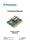
OPC DE - 1
INSTALLATION AND USER MANUAL
© INTESIS Software, SL
Distributed by DURAN ELECTRONICA S.L
Tomás Bretón 50
28045 MADRID, Spain
[email protected]
www.duranelectronica.com
2
© 2010 DURAN ELECTRONICA
ALL rights reserved - www.duranelectronica.com
INDEX
1.
OPC DE - 1. Presentation.......................................................................................................................5
2.
HOW TO PURCHASE AN OPC DE-1 LICENCE FOR EUROSONDELCO/SIEMENS C62P.......................5
3.
EUROSONDELCO/SIEMENS CC62P. Presentation.................................................................................5
4.
PREREQUISITES FOR THE PROPER FUNCTIONING OF OPC DE-1........................................................6
5.
ELEMENTS AND SYSTEM CONNECTION...............................................................................................6
6.
INSTALLING OPC DE-1 IN A PC............................................................................................................7
7.
OPC DE-1 CONFIGURATION...............................................................................................................9
8.
USER INTERFAE...................................................................................................................................10
9.
EXAMPLE OF A WORKING EUROSONDELCO/SIEMENS CC62P CONTROL UNIT.............................10
10
MENUS.................................................................................................................................................15
I-manOPCDE-v03
3
4
© 2010 DURAN ELECTRONICA
ALL rights reserved - www.duranelectronica.com
1. OPC DE-1. Presentation
OPC DE-1 is an OPC Server complying with OPX Data Acces 1.0a to access information supplied by
EUROSONDELCO/SIEMENS CC62P, the toxic and explosive gas measuring and detection system, designed
and manufactured by DURAN ELECTRONICA.
OPC DE-1 is a program for PCs equipped with Windows XP or equivalent, with capacity to operate with up
to 16 control panels per licence.
2. HOW TO PURCHASE AN OPC DE-1 LICENCE FOR EUROSONDELCO/SIEMENS CC62P
Directly contact DURAN ELECTRONICA S.L. or one of its distributors and request one. Once your order
has been accepted, you will receive the software either through email or by downloading from DURAN
ELECTRONICA corporate webpage (www.duranelectronica.com). When executed the software will show
a code which you must send by email to DURAN ELECTRONICA sales dept. DURAN ELECTRONICA will
then send you a licence installation number that will be necessary to complete the installation, and that
authorizes its use.
[email protected]
Inportant note: The licence is valid, exclusively, for the PC in which it is installed. If you try to copy the
licensed program onto another PC, it will not work. The licence is unique for each PC
3. EUROSONDELCO/SIEMENS CC62P. Presentation
EUROSONDELCO/SIEMENS CC62P is a system for detection and measurements of toxic and explosive gases
using electrochemical, catalytic and infrared technology.
A modular system, expandable from 1 to 4 module lines, it allows for the connection of 16 detectors per
module line with a maximum capacity of 64 detectors.
• Every module line may be configured in 1, 2 or 4 toxic gas detection groups -1 dry contact
relay per group/gas- or 1, 2 groups -2 dry contact relays per group/gas- for explosive gases.
• Independent programming of ventilation and alarm levels per group.
• Communication protocol RS485. Compatible with 4-20mA detectors -through optional
interface-.
• Two reading modes per module line -sequential and maximums- and events memory.
• General alarm output for toxic gases.
• General failure output.
• Completely programmable and easy to install: no special instrumentation.
• Complies with the most relevant European regulations for CO detection.
I-manOPCDE-v03
5
4. PREREQUISITES FOR THE PROPER FUNCTIONING OF OPC DE-1
1. OPC DE-1 software is available in Spanish and English languages only. Remember that on the control
unit you must select the language corresponding to the licence you have acquired (Spanish or English); if
you do not, you will not correctly receive messages in the OPC DE-1.
2. The control unit must be readied for integration. Remember you must clearly indicate that the control
unit will be integrated when placing your order.
3. Standards that can be integrated are SPANISH and INTERNATIONAL/PORTUGUESE. Other detection
standards cannot be integrated.
4. The control unit is configured by default in the SEQUENTIAL reading mode. Configuration in this reading
mode is essential for the control unit to cyclically send the measurings from all installed detectors.
5.ELEMENTS AND SYSTEM CONNECTION.
Make sure that installation of EUROSONDELCO/SIEMENS CC62P and its Elements -loop and detectors- has
been completed and the system is functioning correctly.
OPC DE-1 must be connected to EUROSONDELCO/SIEMENS CC62P through an RS232 serial port. The
PC must have as many RS232 serial ports available (RS232 multiport card) as there are control units to
Connect (maximum 16 control units per license).
PC must have Windows XP available, or an equivalent.
Requirements for connection of EUROSONDELCO/SIEMENS CC62P to OPC DE-1 (single control unit):
Connect RS232 connector in the RS232 port on the right side of the EUROSONDELCO/SIEMENS CC62P
control unit and to RS232 port on the PC. If the PC does not include a RS232 port, you will need a RS232
to USB converter. This cable must not be longer than 15 meters (fig 1).
fig 1
If the distance between EUROSONDELCO/SIEMENS CC62P and the PC is more than 15 meters, RS232RS485 converters and RS485 cable must be used as seen in fig 2. Connect RS232 connector in RS232 port
on the right side of EUROSONDELCO/SIEMENS CC62P control unit and to the RS232-RS485 converter.
From the converter, Connect a RS485 cable (up to 1.200 meters long) up to the other converter. From the
second RS232-RS485 converter, Connect a RS232 cable up to the RS232 port of the PC. If the PC does
not have a RS232 port, you will need a RS232 to USB converter.
fig 2
6
© 2010 DURAN ELECTRONICA
ALL rights reserved - www.duranelectronica.com
Requirements for the connection of EUROSONDELCO/SIEMENS CC62P to OPC DE-1 (from 2 control units up to 16)
Connect, independently, each RS232 connector on the RS232 port on the right side of the EUROSONDELCO/
SIEMENS CC62P control unit to the RS232 multiport card of the PC. Remember that for distances greater
than 15 meters RS232-RS485 converters must be used, as seen in fig 3.
Lastly, connect RS232 multiport card to the PC. If the PC does not have a RS232 port, you will need a
RS232 to USB converter.
fig 3
6. INSTALLING OPC DE-1 IN A PC
To proceed with the installation of OPC DE-1 , click on the installation icon in the OPC DE-1 software
(setupv_OPC-DE1_1_0_3). A window will open like that shown below (fig 4). Click on NEXT
fig 4
Following this, a window will appear (see below) suggesting a destination folder in which to install the
program, or an option to change said folder. Once a folder has been assigned, click on NEXT.
fig 5
I-manOPCDE-v03
7
The installation wizard is now going to commence installation. Click on INSTALL
fig 6
fig 7
Lastly, click on FINISH
fig 8
OPC DE-1 program has finally been installed in your PC. To execute it, select it in the programs list and
click on the OPC DE-1 icon. A screen like this will appear.
fig 9
Type in your license number and validate the OPC DE-1 program. If you do not type in a license number
and press ACCEPT you will be able to use a demo version of OPC DE-1 for 15 minutes.
OPC DE-1 is now operational. Proceed with configuration in accordance with the Elements composing the
installed EUROSONDELCO/SIEMENS CC62P.
8
© 2010 DURAN ELECTRONICA
ALL rights reserved - www.duranelectronica.com
7. OPC DE-1 CONFIGURATION
EUROSONDELCO/SIEMENS CC62P continually transmits measurings and status information through the
RS232 port. This information is offered in the form of tags (information units or OPC items) by the OPC
DE-1 Server.
The OPC DE-1 Server offers all tags available for each configured control unit; therefore it is necessary to
know the number of module lines, detectors and groups configured in the control unit to be able to select
them from the OPC client. In this way, it is recommended to select from the OPC client only those tags
that belong to installed detectors.
For example: if in module line 1 a total of 4 detectors have been installed, from the OPC client you should
use only the tags of those 4 detectors, The remaining 12 tags (up to a maximum of 16 of the module line
total) will be available but will not update their information.
Configuration of control units connected to the OPC
In order to configure the number of control units connected to OPC DE-1, go to the Edit-Configuration
menu (fig 10).
Select the connected control units from the list of 16 control units (control units allowed per license)
Remember to select from the list installed control units (only these will be shown in the list of tags).
fig 10
Once a control unit has been selected, select the COM (RS232 port) to which it is connected. the port
selection is independent for every control unit.
Identify the control unit using the Name box.
Timeout Error is the number of seconds the program will wait to receive information from the control unit
before activating the error in communications tag. The default value is 20 seconds. If you decide to change
this value, it is advisable not to set it below 10 seconds (maximum allowed time will be 120 seconds).
If you activate the Start session automatically box, the program will automatically start the session when
launched.
Remember that in order for selected changes to come into effect the program must be closed and opened
again.
I-manOPCDE-v03
9
8. USER INTERFACE
OPC DE-1 has an OPC Server interface and a user interface for the configuration, supervision and testing
of the system.
On the left side all the available OPC items in the OPC Server are shown in tree view (fig 11)
On the right side the selected tag properties are shown (OPC item). They are selected in hierarchical form,
grouped by origin. These properties are:
fig 11
a. Description. Description of the tag functions.
b. Fully Qualified ID. It is the complete tag identification, such as will be displayed in the client
OPC
c. Canonical Data Type. Type of OPC data as per the standard. Offers information on the
Current Value format.
d. Access Permissions. Shows if the tag allows reading and/or writing. In this example all tags
are only read.
e. Current Value. Shows the tag value, it is the property that contains de data. In the case of
tags ending with GasStr, if it shows the gas name this means that there is a detector
connected, if not the box will be empty.
Test mode: to test the systems connected to the OPC Server in case of not having a control unit available,
open session and modify the value in this field typing in a character in the box and pressing the Enter key.
f. Quality. Gives information on data quality following the OPC standard. It should always
indicate Good.
g. Timestamp. Shows date and time in which the tag value was updated from the control unit.
9. EXAMPLE OF A WORKING EUROSONDELCO/SIEMENS CC62P CONTROL UNIT
The main element is the control unit (C01, C02, C03...C16), each one of them having up to 4 module lines
available (Z1, Z2, Z3, Z4) Each module line has a maximum capacity of 16 detectors and may be divided
in 1, 2, or 4 detection groups
The tags list shows all that are possible with control unit al maximun configuration, which does not mean
they are all in use.
10
© 2010 DURAN ELECTRONICA
ALL rights reserved - www.duranelectronica.com
Important: Tags belonging to elements not conected to the control unit will show 0 value (numeric tags)
or blank (test tags). These values can also show up when starting the program and will disappear after a
complete refresh of all elements configured in the control unit.
1. Control Unit Tags (C01 example)
fig 12
Error_Comm: Shows a communications error with the control unit. It is a very important function
because, if active, all other tags will show the last value received.
Values
0
1
OK
Communication error
NPanel: Indicates control unit number. The range of values is between 0 and 50.
2. Module Line Tags (C01, Z1)
fig 13
I-manOPCDE-v03
11
State: Module line status expressed in a numerical form. Depending on the control unit programming and
the measurings of the module line detectors a status will be indicated.
StateStr: Module line status expressed in text form. Values: OFF, ON, PRG.ING, PRG.USER, F.AC, F.BAT,
F.GROUP.
State
1
2
OFF
ON
StsPgrIng
1
2
OFF
ON
StsPgrUsr
1
2
OFF
ON
StsFailPower
1
2
OFF
ON
StsFailBat
1
2
OFF
ON
StsFailGroup
1
2
OFF
ON
3. Detector Tags (C01, Z1, D1)
fig 14
12
© 2010 DURAN ELECTRONICA
ALL rights reserved - www.duranelectronica.com
Gas: Indicates the detector Gas Type expressed in numerical form.
Values
1
2
3
4
5
6
7
8
9
10
11
CO
CO2
NO
NO2
H2S
SO2
CI2
HCI
O2
EXP (explosive gases)
NH3
GasStr: Indicates the gas type of the detector expressed in text form. Values: CO, CO2, NO, NO2, H2S, SO2,
CI2, HCI, O2, EXP, NH3.
Group: Indicates the detection group which the detector is part of. The value range is 1, 2 or 4.
State: Detector status expressed in numerical form. Depending on the control unit programming and the
measurings taken by the detector, a status is shown.
Values
0
1
2
3
4
5
6
7
8
9
NO VALUE
NORMAL
L.VENT1
L.VENT2
ALARM
ERROR
DETECTOR FAULT
WARNING
PRE-ALARM
SATURA
I-manOPCDE-v03
13
StateStr: Detector status expressed in text form. Values: (empty - when detector is measuring 0), L.VENT1,
L.VENT2, ALARM, ERROR, DefFau, Warn, PREALA, SATURA.
Value: Detector measurings. The value range is between 0 and 99999.
99999 Value: Indicates the detector is saturated, that is, measuring a value beyond its measuring
range. This situation is also shown through state tag = 9.
For more information regarding the detection range of the connected detectors, please refer to
the product sheets of the installed detectors and the EUROSONDELCO/SIEMENS CC62P control
panel.
4. Group Tags (example: Control Unit 1, Group 1)
fig 15
Gas: Indicates the gas Type, expressed in numerical form, which is associated to the ventilation group
actuation.
Values
1
2
3
4
5
6
7
8
9
10
11
14
© 2010 DURAN ELECTRONICA
ALL rights reserved - www.duranelectronica.com
CO
CO2
NO
NO2
H2S
SO2
CI2
HCI
O2
EXP (explosives gases)
NH3
GasStr: Indicates detection group gas type in text form. Values: CO, CO2, NO, NO2, H2S, SO2, CI2, HCI, O2,
EXP, NH3.
State: Detection group status expressed in numerical form. Depending on the control panel programming
and detector measurings a status is indicated.
Values
1
2
3
4
5
6
7
STOP
AUTO
MANUAL
VENT1
VENT2
GOFF
V CI
StateStr: Detector status expressed in text form. Values: STOP, AUTO, MANU, VEN1,VEN2, GOFF, V CI.
10. MENUS
1. File - Start/end session: Allows access to the OPC Server configuration - simulation mode, allowing mo
difications to the tag Current Values. Allows closing the program.
You cannot close the program unless session has been started, except by closing Windows, in which case
it will be automatically shut down.
Password is not Case sensitive.
Once a session is started you will no longer have access to available functions.
2. File - Force Server close: Allows disconnecting connected OPC clients. Although the usual procedure is
for the client to disconnect before closing the server, this option allows you the close the server before
the client.
3. Edit - Configuration: Accesses OPC Server configuration.
4. Edit - Change Password: Allows you to change the Start Session password. The default password is
“OPC”, and is not case sensitive.
5. Edit - Language: Allows you to change the program user interface language. There are two choices:
English and Spanish.
6. View - Communications: Useful at a diagnostic level, it accesses the communications bus Viewer,
visualizing communications with the control unit.
6.1. View last: Shows last event received.
6.2. View bus: Activates viewing of events.
6.3. Log to File: Saves events to a DE1.log file situated in the directory where the application has
been installed.
DURAN ELECTRONICA reserves the right to carry out improvements or to include modifications to the equipment without prior notice.
I-manOPCDE-v03
15
© 2010 DURAN ELECTRONICA
ALL rights reserved - www.duranelectronica.com