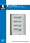
Download Installation user manual
Transcript
Installation & user manual
FIDEGAS C
Control Unit for explosive gases
TABLE OF CONTENTS
1.
DESCRIPTION OF THE EQUIPMENT
2
2.
FUNCTIONING
3
3.
CONNECTION
6
4.
TEST
8
5.
TECHNICAL CHARACTERISTICS
8
5.
WARNINGS
9
6.
GUARANTEE
10
-1–
2004. DURAN ELECTRONICA
www.duranelectronica.com
1. DESCRIPTION OF THE EQUIPMENT
FIDEGAS C2, FIDEGAS C6, and FIDEGAS C12 are Control Units for the detection of explosive gases provided of
4-20mA input standard specially developed for FIDEGAS S/10 detectors.
FIDEGAS C2 -up to 2 detectors•
•
•
•
LED ON
PREALARM level independent for each detector, marked as P1 & P2 –LED yellow-.
ALARM level independent for each detector, marked as A1 & A2 –LED red-. The Control Unit will
memorise this event until it is manually deleted.
OUTPUT LED
§ ON. –green- the output is activated. The cut-off gas valves are powered.
§ OFF. the optical-acoustic alarms are powered.
•
PREALARM OUTPUT that can be activated by any of the connected detectors. There is no visual
indication for this output’s state.
•
RESET button, located in the panel -red box label-. After an alarm event, reset the system by pressing it
for 2 s just until the red LEDs A1 & A2 light off and the green OUTPUT LED light on. If in two or three
seconds the red LED does not light off the detector could be detecting gas up to 20% L.E.L. or there is a
system failure.
FIDEGAS C6 -up to 6 detectors•
•
•
•
LED ON
ALARM level, independent for each detector –red LEDs marked with detector numbers 1, 2, 3, 4, 5 & 6.
The Control Unit will memorise this event until it is manually deleted.
OUTPUT LED - 1 or 2§ ON, the output is activated. The shut-off gas valves are powered.
§ OFF, the optical-acoustic alarms are powered.
PREALARM OUTPUT that can be activated by any of the connected detectors. There is no visual
indication for this output’s state.
FIDEGAS C12 -up to 12 detectors•
•
•
•
LED ON
ALARM level, independent for each detector –red LEDs marked with detector numbers 1, 2, 3, 4, 5,
6,etc…. The Control Unit will memorise this event until it is manually deleted.
OUTPUT state led (green led labelled as OUTPUT 1, OUTPUT 2, OUTPUT 3 and OUTPUT 4), when it is on
the output is activated and the connected gas shut off valves are energised; when it is off the output is
not active and the optical-acoustic alarms are energised instead.
This central unit is provided with a PREALARM output, activated by any of the connected detectors at
10 % L.E.L. (Lower Explosion Limit) and there is no visual indication of this output’s state.
RESET button, located in the front panel as a red box label to reset the system after an alarm event.
Keep pressing 2 s just until the red LEDs, A1 and A2, light off and the LED OUTPUT -green- light on. If
in 2 or 3 s the red LEDs do not light off, then the detector is still detecting gas or there is a system
failure.
A gas detector is not the substitute of a correct installation and maintenance of gas appliances and must be
installed by a competent person or an authorised installer.
-2–
2004. DURAN ELECTRONICA
www.duranelectronica.com
2. FUNCTIONING
1. Connect the FIDEGAS S/10 detectors to the FIDEGAS C2, C6 or C12 Control Units.
INSTALLING FIDEGAS S/10 DETECTORS
Install the detectors avoiding air flows and places where dust and dirt can block the protection filter of
the sensor, bearing in mind its coverage area of 15 m2.
Do not install in small closed areas (as closets, etc).
BUTANE / PROPANE
METHANE / NATURAL GAS
25cm from floor.
15cm from ceiling.
Jump "S" to "⊥" if one of the detectors is not going to be installed.
2. Connect the Control Unit to the mains supply -230V AC-. The ON LED -green- will light up and a few
seconds later the ALARM LED -red- will also light up. The OUTPUT LEDs will remain off.
3. After approx. 20 s and by pressing RESET the system will be reset.
4. The ALARM LEDs light off -if there is no presence of gas or a wrong connection- and the OUTPUT LEDs –
outputs 1 & 2 for FIDEGAS C6 & FIDEGAS C12- will light on.
5. Now the Control Unit is ready to detect.
PREALARM LED.- It will light up to indicate that the gas concentration has exceed the 10% L.E.L.. It will activate
the PREALARM output -P1 or P2 LEDs-. This output remains active for about 2 minutes after reaching 10% L.E.L.
signal. The output is located at the PREALARM connectors -12V DC & 230V AC-.
ALARM LED.- It will light up to indicate that the gas concentration has reached 20% L.E.L. The corresponding
ALARM LED -A1 or A2- will light on, showing what detector activated the alarm. The output of the detector in
alarm will stay inactive. The rearming will be carried out by pressing RESET until the corresponding ALARM LED
light off and the OUTPUT LED light on.
In FIDEGAS C6 & C12, A strip line is reserved at the front panel of the Control Unit, next to each ALARM
LED to indicate the location the detector.
AUXILIARY BATTERY –Optional-. - The Control Unit is provided of a connection for auxiliary battery that avoids
operation interruptions due to eventual mains faults. The autonomy of the battery full loaded is about 45 min.
The alarm central unit is provided with its own battery charger system and it avoids battery discharge in normal
operation.
-3–
2004. DURAN ELECTRONICA
www.duranelectronica.com
OUTPUT ADDRESSING SELECTION (FIDEGAS C6).- The central unit is provided with two microswitches that allow
selection of the outputs that will be activated by each detector, OUTPUT 1 or/and OUTPUT 2. The microswitches
are located at the circuit board and they are numbered with each detector number. Selection of the output for
each detector is made when the switch of a detector is at ON position for OUTPUT 1 or OUTPUT 2, or both. Make
sure that they are not at OFF position or at an intermediate position.
-4–
2004. DURAN ELECTRONICA
www.duranelectronica.com
OUTPUT ADDRESSING SELECTION (FIDEGAS C12).- The central unit is provided with two microswitches at each
circuit board named as S1 and S3 for upper board and S4 and S4 for lower board. They allow selection of the
outputs that will be activated by each detector, OUTPUT 1-2 or/and OUTPUT 3-4. The microswitches are located
at the circuit board and they are numbered with each detector number. Selection of the output for each
detector is made when the switch of a detector is at ON position for OUTPUT 1-2 or OUTPUT 3-4, or both. Make
sure that they are not at OFF position or at an intermediate position.
If a detector has to actuate on a specified output, the switch named with the detector number shall be in the
ON position at microswitch group corresponding with that output.
-5–
2004. DURAN ELECTRONICA
www.duranelectronica.com
3. CONNECTIONS
FIDEGAS C2: CONNECTIONS DIAGRAMS
-6–
2004. DURAN ELECTRONICA
www.duranelectronica.com
FIDEGAS C6 & C12: CONNECTIONS DIAGRAMS
-7–
2004. DURAN ELECTRONICA
www.duranelectronica.com
4. TEST
To verify the right operation of the gas detector use a gas tester corresponding to the same type of gas,
allowing the gas to come out as near as possible of the metallic mesh filter until the detector alarms. Repeat
this operation EVERY TWO MONTHS.
Do not use other methods that may draw false conclusions, such as gas lighters, flammable vapours, etc.
5. TECHNICAL CHARACTERISTICS
FIDEGAS C-2
FIDEGAS C-6
FIDEGAS C-12
230V CA 50/60 Hz
230V CA 50/60 Hz
230V CA 50/60 Hz
10W
20W
40W
Capacity
2 detectors
6 detectors
12 detectors
Prealarm Output
12V DC / 230V AC
12V DC / 230V AC
12V DC / 230V AC
Outputs with voltage
1 at 12V DC / 230V AC 2 at 12V DC / 230V AC 2 at 12V DC / 230V AC
Maximum power at 12V DC
0.25A 3W
0.5A 6W
0.5A 6W
Voltage
Maximum power at 230V AC
Actuation levels
Working/ storage temperature
Working/ storage humidity
Protection grade
Dimensions (mm)
Weight (gr)
Auxiliary battery (optional)
SERIAL NUMBER
-8–
2004. DURAN ELECTRONICA
www.duranelectronica.com
100W
2
From -5ºC to 50ºC
100W
2
From -5ºC to 50ºC
100W
2
From -5ºC to 50ºC
From 30% to 90% RH
From 30% to 90% R.H.
From 95 to 110 kPa.
From 30% to 90% R.H.
From 95 to 110 kPa.
IP 435
355 x 260 x 85
4,300
12V 3Ah.
IP 435
355 x 260 x 85
4,800
12V 3Ah.
IP 435
355 x 260 x 85
5,500
12V 3Ah.
45 min autonomy full charge
30 min autonomy full charge
20 min autonomy full charge
6. WARNINGS
•
Make sure that the FIDEGAS S/10 detectors are correctly connected.
•
Use shielded cable for the connection Control Unit-detector with minimum section of 4 x 0.25 mm2.
Connect the mesh shield to “COMUN DE MALLAS” according to the diagram.
•
For FIDEGAS C2 make sure the connection of "S" to "C” -COMUN MALLAS- is made when those
detectors are not in used.
•
For FIDEGAS C6 & FIDEGAS C12 make sure that the connection “⊥” -COMUN MALLAS- is made when
detectors are not in used.
•
Make sure that the supply voltage is 230V AC.
•
If an auxiliary battery has been installed, make sure the polarity is correct: positive (+) to red and
negative (-) to black.
•
Make sure the fuses values are optimal for the right operation of the Control Unit and can not be
changed.
•
Do not sink, wet or spray with any liquid.
•
Avoid painting with synthetic paintings close to the detector.
•
When the detector is for BUTANE/PROPANE and, therefore, it is installed close to the floor, avoid
cleaning near the detector with detergents containing bioalcohol, industrial solvents or other products
with silicon in suspension (shiners).
•
The detector must not be in contact whit SILICONE VAPOURS, TRICLORINETHYLENE, SULPHUR DIOXIDE
OR HYDROGEN SULPHIDE, since the sensor might irreversibly get damaged. Do not use cables containing
silicone for the connection of the detector.
•
Take into account that none of the detector elements should be manipulated, nor the adjustment, since
it might cause an irreversible failure of the unit or an electrical shock.
•
Take into account that the non observance of these basic rules may damage the unit and the
manufacturer declines any responsibility of the damage it could cause.
-9–
2004. DURAN ELECTRONICA
www.duranelectronica.com
7. GUARANTEE
DURAN ELECTRONICA guarantees this equipment against any manufacturing defect for 1 year from the
date of purchase. If during this period of time any anomaly is detected, please advise your supplier or
installer.
The guarantee covers the total repair of the equipment that the DURAN ELECTRONICA technical services
consider to be defective, so that the equipment can return to its normal use. This guarantee will only be
valid if the equipment has been installed by a competent person and following the specifications in this
manual. Negligent use or installation will exempt DURAN ELECTRONICA from its responsibilities for
damage caused to property and/or people and from the fulfilment of the terms of this guarantee.
The guarantee does not cover:
•
Installations, periodical checks and maintenance.
•
Repairs caused by improper handling, inappropriate use, negligence, overload, insufficient
power supply or neglecting the equipment, voltage shorts, defective installations and other
external causes.
•
Repairs or adjustments carried out by personnel not authorised by DURAN ELECTRONICA.
•
The equipment transport costs.
DURAN ELECTRONICA reserves the right to carry out improvements or to include modifications to this
equipment without prior notice.
- 10 –
2004. DURAN ELECTRONICA
www.duranelectronica.com
I-manfidegasC-v01
C/ Tomás Bretón, 50
28045 MADRID, Spain
Tel.: +34 91 528 93 75
Fax: +34 91 527 58 19
[email protected]
www.duranelectronica.com


