1
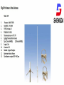
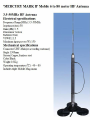
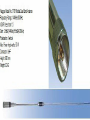
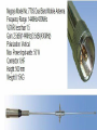
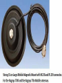
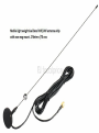
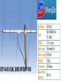
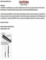
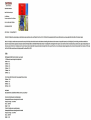
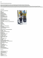
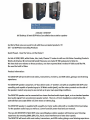
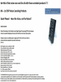
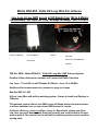
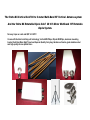
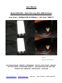
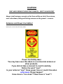
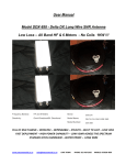
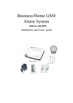
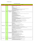
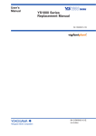
SHENGDA
SHENGDA COMMUNICATION
144/430MHz Dual band Omni Antenna
SDBF1.2E
Electrical specifications
Frequency Range(MHz)
Bandwidtb(ME3z)
Polarization
144/430
10
Vertical
Impedance
50 Ohm
Gain (dBi)
Radiation
Horizontal Beam Width
Vertical Beam Width
VSWR
Maximum input power (W)
Lighting Protection
3. 0/6.0
Omni
360°
57°
<1.5
100
Direct Ground
Mechanical specifications
Connector
Connector position
Length
Packing weight (kg)
S 0-239 or customization
Radiating Material
Radome Material
Color
Cu
Operating temperature ( G )
Material of Hardware-supplied
Mounting hardware (mm)
Bottom
1200±20 mm
1.2
Fiberglass
White
-50-70
Metals
031.5mm
High Performance Omni Antenna
Model: X30
l.
2.
3.
4.
5.
d.
7.
8.
10.
11.
12.
13.
Frequency: 1+4/430 AIHz
Gam (dBi) : 3.0/5.5 dBi
VSVVR: less than 1.5
SHENGDA
.
Polarization: Vertical
Maximum input power (W): 150
Lighting Protection Direct Ground
2x5/8wave (430/MElz)
Type:1'2wave (1++MHz)
Length: 1.3m
Connector: MJ
Material : Copper, Fiberglass
Rated wind velocity: dOm/sec
Mast diameter accepted: 03O~0d2 mm
r
M
V\V1
f
h
To
\\
MERCURY MARK II1 Mobile 6 to 80 meter HF ADteona
B
3.5-50MHz HF Antenna
Electrical specifications
Frequency Range(MHz) 3.5-50MHz
Impedance(ohm) 50
Gain (dBt) 3. 5
Polarization Vertical
Radiation Omni
VSWR<1.5
Maximum input power (W) 150
Mechanical specifications
Connector UHF-Male(or according customer)
Height 1300mm
Material Cupper,Stainless steel
Color Black
Weight 0.3Kg
Operating temperature (tl! ) -40 SO
includes triple Mobile Mag-motm
-
1
Nagoya Mode] No.:77GR Mobile Dual Band Antenna
Frequency Range: 144MHzf430MHz
VSWR: lass titan 1.5
Gain: 3.5dBi(144MHz}fl»j5d Bi(430M Hz)
Polarization: Vertical
Wax. Power I r put-watta: 50 W
Connector: UHF
Height: SBO mm
Weight:0.2KG
m
$
Jj
Nagoya Model No.:770S Dual Band Mobile Antenna
Frequency Range: 144MHz/430MHz
VSWR: less than 1.5
Gain: 2.5dBi(1 44MHz)/3.5dBi(430MHz)
Polarization: Vertical
Max. Power Input-watts: 50 W
Connector: UHF
Height: 500 mm
Weight:0.15KG
t
V
Strong IS cm Large Mobile Magnetic Mount with RG 58 and PL 259 connector.
For the Nagoya 770R and the Nagoya 770s Mobile antennas.
Mobile light weight dual Band VHF/UHF antenna whip
with own mag mount. 2 Meters /70 cms
m
\i
it'
s
I
m..
Dual Band Rubber Duck
i
Super Booster Antenna
for Hand-Held with SMA
fitting. For that extra
boosted signal.
SHENGDA
Model No: RH771
Frequency Range: 144/430MHZ
Impedance: SO Ohm
VSWR: Less thanl.5
Gain: 3.5 dBi
Polarization: Vertical
Radiation: Omni
Maximum Power Input-watts: 50 W
Connector: BNC/SMA-Male/SMA-Female/MX/TNC
Radome Material: TPEE
Radome Color: Black
Weight:0.05KG
L,
J “
1
h
S
/
/
/
.
v
I
/
r
/
/
SDY1 4
ft
/
BAND VHF/UHF YAOt
>
ShengDa
2 m/70 cm
2m 9.5dBi/70cm
Gain:
11.15dBi
VSWR:
1 5: 1 or less
Max Power: 100 watts FM
Boom Length: "130mm
1.2Kg
Weight:
Connector:
N Female
Rated Wind
Velocity:
GO m/s
Model DDX-858 - Delta DX Long Wire Snr Antenna
Low Loss & Low SWR across all HF Bands from 160 to 6 Meters
Revolutionary - No Traps - No Coils - No plugs to change - QRP to 1KW !!!
Frequency Band(s):
HF and 6 Meters
Brand:
Directivity:
Omni-Directional/BiDirectional
Model Name:
DELTA DX LONG WIRE SNR
Model Number::
DDX-858
Delta DX
THE ALL NEW:- Model DDX-858 - 'Delta DX Long Wire SNR' Antenna System
Portable & Base Antenna for Amateur and Commercial Radio Operation
Low Loss – TX and RX on all HF Bands & 6 Meters - from 1.8 to 54 MHz
Stealth and No inconvenient coils, jumpers or plugs to change
Handles QRP to 1 KW
60 Foot Long Wire with built-in matching system - Simple to install and Deploys in
5 Minutes
This antenna system offers a low SWR across all Bands without an antenna tuner,
or with an antenna tuner, an even lower SWR across the bands.
It delivers efficiency, does not utilize a lossy 9:1 Balun/Unun system and offers
Low Loss across all bands, when deployed correctly and as described in the user
guide supplied. The system has it's own built in matching system and no sensitive
moving parts.
Can be used as a Sloping Wire with the long wire sloping upwards from the
matching unit, making it Bi-Directional or as an inverted L, using the long wire,
which makes it omni-directional. For the more adventurous, enjoy experimenting
with other configurations.
A simple to install, high quality, antenna, made of the highest quality materials, all
hardware fittings made of Marine Grade Stainless Steel.
Long Wire Element is highly durable and UV Resistant, with a porcelain end
connector (Porcelain connector shapes may differ from picture).
Offers the best Value for money.
When considering the price of this, please keep in mind what this antenna is
capable of i.e:Handles up to 1 Kilowatt - Low Loss and Low SWR from 160 thru 6 meters
5 Minute deployment - base and portable.
-
No coils, jumpers or plugs to change, no sensitive moving parts - Stealth !!!
Includes:
1 X Delta DX Matching Unit
1 X 60 FT Wire Element
Marine Grade Stainless Steel Hardware
The ‘Delta DX Vertical Gold’ 80 to 6 meter Multi-Band HF Vertical Antenna system
And the ‘Delta DX Rotatable Dipole Gold’ 40 t0 6 Meter Multiband HF Rotatable
dipole System.
No lossy traps nor coils and QRP to 1KW !!!
Comes with the latest matching unit technology, Vertical Mil Whip or Dipole Mil Whips, aluminum mounting
bracket, Solid two Meter High Tripod and Superior Quality Carry bag. Hardware of marine grade stainless steel
and high quality chrome plated brass
Two Great options
The ‘Delta DX Vertical Gold’ 80 to 6 meter Multi-Band HF Vertical Antenna system
And the ‘Delta DX Rotatable Dipole Gold’ 40 t0 6 Meter Multiband HF Rotatable
dipole System.
Base & Portable Antenna
QRP to 1KW !!!
Low Loss, High performance !!!
Marine Grade Stainless Steel Hardware !
Stealth - Simple to install and Deploys in 15 Minutes
A simple to install, high quality, antenna, made of the highest quality materials, all hardware fittings made of Marine Grade
Stainless Steel.
Includes standard:
1 X Delta DX Matching Unit
1 X Vertical Mil Whip (or 2 X Rotatable Dipole Mil Whips)
1 X Mounting Bracket (Single type for Vertical or double type for rotatable dipole)
Marine Grade Stainless Steel and Chrome plated Brass Hardware
1 X High quality, strong, two Meter High Tripod
1 X Superior Quality Carry bag to carry entire antenna system
User Manual
Model DDX-858 - Delta DX Long Wire SNR Antenna
Low Loss – All Band HF & 6 Meters - No Coils 1KW !!!
Frequency Band(s):
HF and 6 Meters
Brand:
Delta DX
Directivity:
Omni-Directional/Bi- Directional
Model Name:
DELTA DX LONG WIRE SNR
Model Number::
DDX-858
FULL HF MULTI-BAND – VERSATILE – DEPENDABLE – STEALTH – BUILT TO LAST – LOW LOSS
FAST DEPLOYMENT – HIGH POWER CAPABILITY – LOW VSWR ACROSS THE SPECTRUM
STAINLESS STEEL HARDWARE – WATER PROOF – LONG WIRE
www.antennaworld.co.za
[email protected]
CAPE TOWN
PHONE: 021 439 2362
MOBILE: 073528 4950
CAUTION
FIRST AND FOREMOST NEVER TAKE CHANCES – SAFETY ALWAYS FIRST
Always install antennas securely so that there will be no risk of the antenna,
mast or hardware, falling and hurting someone on the ground... or worse.
Antennas and Power Line Safety!
Extract form an article Ref Chuck Kraly, K0XM
Power line Safety label.
You may have seen this label on a commercial antenna or
other products.
If you did not take a moment to read it carefully,
Notice the word "near".
Is your antenna "near" those power lines or could it be when
unforeseen things happen?
How close is "too close"? How close is "near"?
In this article, Chuck Kraly, K0XM attempts to inform you of
the EXTREME DANGER posed by installing an antenna, any
antenna, to close to power lines. Now don't make the mistake
and say that cannot happen with your antenna, it is made
from fiberglass or other material which is an
insulator!....you may be "dead" wrong!
Read on......
Most new hams are excited when they get their license and
they want to get on the air as soon as possible. Many of them
have not given a thought to the actual installation of an
outside ham antenna and the dangers involved other than
getting it up as high as they can and having it fall on them.
If you don't read any more of this article, then remember just
this very simple statement when putting up any ham
antenna,
"If there is a power line, including the drop line going to your house, over, under
or within a thousand feet of the antenna, IT could FALL AND hit your antenna and
YOU while you are installing it!.
Although the thousand feet is bit of an exaggeration, PLEASE ,PLEASE follow the
warnings. ANYWHERE close is too close.
The most important thing you can do FIRST, when installing an antenna, is to
LOOK before any part of that antenna, tower, mast or antenna support or any part
of that antenna "system" ever gets off the ground. This includes the guy
wires...what if suddenly one breaks and flies into a power line. You or someone
else is in contact with the mast, or tries to stop the guy wire.. bang,
your dead!
The principle is very easy. Go outside and consider every possible location for
your antenna. Then look at each possible location with the DANGER aspect added
to it. Where are the nearest power lines? Are you in the open, or are there trees in
the area?
Look behind the trees or inside the foliage where they might be lurking, just like a
rattle snake hiding there waiting to "strike".
Many times it's the power lines out in plain site that will get you or one of your
helpers or all within its reach!
Then, the SECOND thing you need to do is to get another pair of eyes from a
helper to do the same thing...LOOK again at ALL possible hiding places for the
danger of power lines and remember, it is the power line that you don't see or the
one that you are not too concerned about that will terminate your fun.
ASSUME THE WORST WILL HAPPEN!
Now consider that most guyed antennas like verticals are supported on
"something". It may be a metal mast on the ground, a short metal "tower" with
legs on the roof, or a wooden pole or other supposed "non-conductive material. Is
it conductive to high voltage?
Would you bet your life or your help on not knowing for sure?
Assume that everything the antenna is mounted on AND EVERY THING it is
connected to is conductive. Don't gamble your life on the words, "I think it is nonconductive"!!!
Assume that the guy wires are conductive. If one breaks and snaps back or
"accidentally" slips out of yours or a helpers hand, which direction will it likely
go...toward the power line? If it is under much tension at all, it will act like a
whip...Here comes Murphy’s Law....
IT WILL go toward the direction of the power line!
Now, assume a domino effect. If your vertical falls toward a small tree that can't
take it's weight, the tree will fall, INTO A POWER LINE....the power line connects to
the tree, the tree is connected to the antenna or a portion of it, and it is connected
to you....that domino effect just bit you like that rattle snake with a LETHAL BITE!
In short, assume that the antenna or any portion of it including it's guy wires, feed
lines, support, etc. WILL fall or break while you are putting it up "near" power
lines. If any power lines are within "striking" distance of ANY portion of the
antenna or it guys, support ropes, etc.....you may wish...for a split second, that
you had planned your life much better rather than being in a hurry and court
disaster.
So far, we have talked about vertical type antennas. You should apply the above
tips to ANY ham radio antenna, or antenna installation no matter how it is
designed, how small or what it is made of. Your antenna is your "friend" but it or
any part of it could be your enemy!
Plan far ahead with these tips:
Let others know what you will be doing and not just the person or persons helping you.
All of you may need emergency care and no one may be able to call for it.
If you are not sure what you are doing, get expert help!
Plan your steps as if your life and those around you depend on it.
Notify a family member or neighbor that you will be putting up the antenna. Ask
them to keep an eye AND an ear out for you...
HAVE EVERYTHING WELL PLANNED.
NO ALCOHOL OR DRUGS! WHILE INSTALLING ANTENNAS.
Get a good night’s rest before the big day.
Have a clear mind when you are installing antennas.
Have more than enough help.
Make sure all those involved with the installation know exactly what will be done
and in the proper steps. Make a plan and let your helpers know ALL of the
details...
Make sure all concerned know what to do if the antenna or any part of it starts to
fall toward a power line.....simple....let go....get as far away as possible from ANY
part of the antenna.....let it fall...DO NOT TRY TO KEEP IT FROM FALLING INTO
THE POWER LINE.....YOUR EFFORTS COULD BE LETHAL.
Do not try to install the antenna in bad weather with wet ground, snow, ice, etc.
There is an old ham saying, "Bad weather is the best weather to put up an
antenna". Don't believe it. Mother nature loves to disrupt antenna installations and
get you hurt or .....worse.
NEVER, NEVER, NEVER put up or even think about putting up any kind of antenna
when you can hear thunder. If you can hear thunder in the distance, lightning can
strike you!
some or all of the material above will help at least one of you save your life or
others. Pass this information along and get the word out...be safe...
and enjoy ham radio.
Introduction
Thank you for purchasing and using the Model DDX-858 - Delta DX Long Wire Snr HF antenna system.
The system comprises of the following:
60 feet of wire
Delta Match
Isolation loop
Stainless steel attachment hardware
Porcelain Insulator
The Insulator is permanently attached to one end of the Model DDX-858 Antenna Wire Connector Antenna
Connection
The Antenna Connection is located on the top of the Matcher. It is a 3/8” x 24 (fine thread) female fitting.
Counterpoise Connection
The Counterpoise Connection is located on the bottom of the Model DDX-858 Matching unit It is a 3/8” x 24 (fine
thread) male fitting, with two nuts. Optional counterpoise cables may be fitted and tighten between the two stainless
steel nuts.
Antenna Shackle
The Antenna Shackle assembly, consists of a shackle, bolt, and nut. It is attached to the top of the matching unit.
Carabiner
The Carabiner is a removable pear-shaped stainless steel hooks with a spring-loaded gate.
Antenna Configurations
Using the supplied components, the Model DDX-858 can be deployed in various configurations. These are just some of
the configurations that this versatile antenna system can be utilized for, more options on request.
A. Sloping Wire with the long wire sloping upwards from the matching unit.
B. As an inverted L using the Long Wire.
C. As a dipole in the field or base, using an optional extra Long Wire
Sloping Wire Configuration
The Sloping Long Wire configuration, is a broadband short to long range HF antenna. It is designed to provide
acceptable ground wave and sky wave propagation. This configuration is predominately omnidirectional, becoming
slightly bidirectional towards both ends of the antenna wire as the frequency increases. The Sloping Wire requires one
support and should be mounted at a height of 25 to 40 feet for best performance. A counterpoise wire, with a length
of 20 to 40 feet, is recommended. If a counterpoise is not used, the coaxial cable must be 25 to 100 feet in length, as
the shield of the coaxial cable provides the counterpoise.
Site Selection and Preparation.
1. Select a site to deploy the Model DDX-858 Sloping Wire configuration. The site must have a support that will
position the end of the Antenna Wire at a height of 25 to 40 feet. If the right support is unavailable, any convenient
object, such as a fence post or the top of a vehicle, may be used as a field expedient support with reduced
performance, But always follow the safety precautions above.
2. If not already attached, connect a Carabiner to the Wire Connector end of the Antenna Wire.
Connect the Matcher. Refer to steps (3) – (7) below.
3. Temporarily remove the Antenna Shackle from the Antenna Connection.
4. Place the Wire Connector from the Antenna Wire over the Antenna Connection and replace the Antenna Shackle.
Tighten the nut snugly.
5. Connect the Carabiner from the Antenna Wire to the Antenna Shackle.
6. If using a counterpoise wire, connect it to the Counterpoise Connection . Tighten the nut snugly.
7. Connect coaxial cable the UHF Socket on the matcher.
Raise the Antenna.
8. Using a Bowline or similar knot, tie the end of a short length (around 4 feet) of Paracord to the Carabiner from step
(5).
9. Drive a Stake into the ground near the location closest to the radio set and tie the Paracord from the Hybrid Base to
the Stake using two Half Hitches, or similar knot.
10. Using a Bowline, or similar knot, tie a long length (50 feet or more) of Paracord to the Insulator or Isolation Loop
at the end of the Antenna Wire.
11. Using a throw weight or some other method, loop the Paracord over the support.
12. Raise the end of the Antenna Wire to the desired height, such that the Antenna Wire is not quite taut, and secure
it to the support using a Round Turn and two Half Hitches, or similar knot.
Extend the Counterpoise.
13. If using a counterpoise wire, extend it along the ground in any convenient direction.
14. Perform operational test.
15. This completes deployment of the Sloping Wire configuration.
Inverted “L” Configuration
The Inverted “L” configuration is a broadband short to long range HF antenna. This configuration tends to be
unidirectional, favoring the horizontal end of the antenna. It is also provides effective ground waves communication
during the day time on frequencies between 1.8 – 4.0 MHz without using sky wave propagation. The Inverted “L”
requires two supports and should be mounted at a height of 25 feet for best performance. Though, it will provide
good performance at a height of 10 to 20 feet, and is usable when mounted as low as three feet. One counterpoise
wire, with a length of 20 to 40 feet, is recommended. If a counterpoise is not used, the coaxial cable must be 25 to 100
feet in length, as the shield of the coaxial cable provides the counterpoise.
Site Selection and Preparation.
1. Select a site to deploy the Inverted “L” configuration. The site must have two supports that will position the corner
of the “L” and the end of the Antenna Wire at a height of 25 feet. If the right supports are unavailable, any convenient
objects, such as fence posts or the tops of vehicles, may be used as a field expedient supports with reduced
performance.
2. If not already attached, connect a Carabiner to the Wire Connector end of the Antenna Wire.
Connect the Matcher. Refer to steps (3) – (7) below.
3. Temporarily remove the Antenna Shackle from the Antenna Connection .
4. Place the Wire Connector from the Antenna Wire over the Antenna Connection and replace the Antenna Shackle.
Tighten the nut snugly.
5. Connect the Carabiner from the Antenna Wire to the Antenna Shackle.
6. If using a counterpoise wire, connect it to the Counterpoise Connection. Tighten the nut snugly.
7. Connect the coaxial cable or to the UHF Socket on the Matcher.
Raise the Antenna.
8. Using a Bowline or similar knot, tie the end of a short length (around 4 feet) of Paracord to the Carabiner from step
(5).
9. Drive a Stake into the ground near the location closest to the radio set and tie the Paracord from the Hybrid Base to
the Stake using two Half Hitches, or similar knot.
10. Using a Bowline or similar knot, tie a long length (50 feet or more) of Paracord to the Insulator or Isolation Loop at
the end of the Antenna Wire.
11. Using a throw weight or some other method, loop the Paracord over the support closest to the radio set.
12. Pull the Paracord and end of the Antenna Wire over the support.
13. Using a throw weight or some other method, loop the Paracord over the other support.
14. Pull the Paracord, such that the Antenna Wire is not quite taut, and secure it to the support using a Round Turn
and two Half Hitches, or similar knot.
15. If using a counterpoise wire, extend it along the ground under the antenna.
16. Perform operational test.
17. This completes deployment of the Inverted “L” configuration.
Troubleshooting
1. If using the Antenna Wire , ensure Wire Connector is securely connected.
2. Inspect Antenna Wire for breakage or signs of strain.
3. Ensure UHF Plugs are securely tightened.
4. Inspect Coaxial Cable assembly for cuts in insulation or exposed shielding. Replace if damaged.
5. If still not operational, connect a Standing Wave Ratio (SWR) Power Meter and check SWR.
6. If SWR is excessively high, check antenna tuner or coupler using the technical manual or manufacturer’s procedure.
Be sure to check the Coaxial Patch Cable that connects the radio set to the antenna tuner or coupler.
7. If still not operational, replace Coaxial Cable assembly. Most problems with antenna systems are caused by the
coaxial cables and connectors.
8. Connect a Multi-Meter to the Antenna Wire to check continuity. Replace assemblies that do not pass a continuity
check.
9. If still not operational, contact your dealer, who will be able to assist further a quickly get you back on the air.
Specifications
Frequency:
1.8 – 54 MHz
Power:
Model DDX-858 - Delta DX Long Wire SNR Antenna: 1000 Watts PEP SSB
RF Connection: UHF Plug (PL-259)
SWR: Subject to frequency and configuration.
Personnel Requirements and Setup Time: Less than 10 minutes.
Optional Accessories
Counterpoise Kit. The Counterpoise Kit is ideal for portable antenna deployment. The system will create the groundplane needed to any vertical antennas and will also play the role of guy wires. It contains four wire radials secured
around plastic wire winders and four steel tent stakes.
Recommended non-supplied accessories
The following hardware is needed to attach the counterpoise wires to the matcher base.
Wide range antenna tuner required on certain bands.
Flashlight.
Multi-tool.
Throwing weight and string.
Mallet.
SWR Power Meter.
Multi-Meter.
50’ Paracord and Line Winder.
Counterpoise Wire/s
www.antennaworld.co.za
[email protected]
CAPE TOWN
PHONE: 021 439 2362
MOBILE: 073528 4950