1
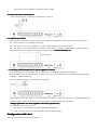
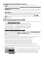
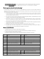
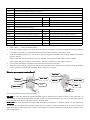
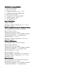
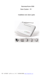
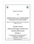
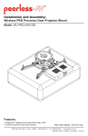
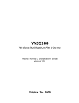
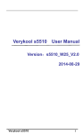
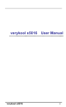
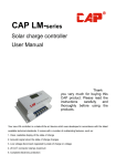
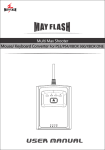
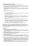
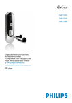
Business/Home GSM
Alarm System
Model No.: GSM-007M
Installation and Users’ guide
Brief Introduction:
◆
◆
◆
◆
◆
◆
◆
◆
◆
◆
◆
◆
◆
◆
◆
◆
◆
GSM 900/1800MHZ bands, can be used in most parts of the world
Full duplex (2-way) communication with the host (optional)
Voice-monitoring the scene environment
Voice and message alert
Set alarm ON or OFF (Arm/disarm) by remote controllers
Can set Home Arm and Out Arm mode and time-delay alarm
Call in to set alarm ON/OFF, Monitor, Output, and Intercom.
Send SMS to set alarm ON, OFF, Monitor, Output
5 group phone +Room/zone number
1 group alarm monitor center phone number
2 group phone to report arm and disarm status
Can program 5 groups of alarm messages
3 zones for wired detectors
99 zones for wireless detectors
2 outputs, can be used with external circuit to control home appliance
Easily set ON or OFF for every wired or wireless detector
SMS alert if external power failure or recovery
Basic Kit contains:
-
GSM Alarm system (control unit) – 1 pc.
Wireless PIR detector – 1 pc.
Wireless door (gap) sensor – 1 pc.
Remote controller – 2 pcs.
GSM Antenna – 1pc.
Mini wired siren 110dB/0.3m – 1 pc.
Power supply (adapter) – 1pc.
Installation/user manual – 1pc.
Installation guide:
1. Insert SIM in alarm unit.
Press the yellow point on top of the main unit with a pencil tip or other tools, SIM tray will come out. Put the SIM
card carefully into the tray, and make sure the metal contacts of the SIM to be down.
Note
Note: Before inserting SIM card into alarm unit, using a regular mobile phone to do the following steps:
- Set PIN code request to off.
- Delete all stored numbers.
2. Connect the antenna.
Screw the antenna to the connection on top of the main unit. Take care not to over-tight the nut or let it loose!
3. Insert the power supply.
Connect the host with the adaptor. The host need 9V-12V DC, must be over 1000mA current.
� The signal status LED on the main unit panel will turn to red and last for 20 seconds, this is code learning
mode, system is waiting for wireless detectors to be coded into the host;
� After 20 seconds, the signal status LED will turn to orange, and begin to flash, indicating system is checking
SIM card and search for GSM network;
� After main unit finish checking the host, if the signal status LED turns to green and flashes slowly, it shows
alarm phone number have been saved in the host, and the host is in arm status. If the signal status LED keeps
on in green, it shows phone numbers have not been saved in the host, and the host is in disarm status. You can
dial in the host or send SMS to program the phone number.
4. Connect the siren to alarm system
system.
Connect the black wire to GND port and red wire to siren port.
5. Connect wired sensors
sensors..
Three inputs are available to connect wired sensors. Inputs are independent, and are not coded as different zones.
� Sensors must be NC (normally closed) type.
� More than 1 sensor can be applied at one input, connecting their alarm contacts serial.
� The inputs can be connected with any number of wired sensors, as long as total resistance is under 220 ohms.
When these sensors are triggered, the alarming message will be: Wired Activated (1~3).
6. Connecting switched output devices (Home-appliance Control)
Three open outputs (O1, O2 and O3) and one internal relay controlled by telephone are available.
Internal onboard relay is activated when an alarm occurs and can be deactivated / reactivated through telephone
commands or SMS text message.
It can be used, for example, to command an external light.
Open outputs can be used directly if your equipment can operate a relay. Do connect an anti parallel diode with
relay coil. These outputs can be operated only by telephone or SMS text message commands.
Wiring Explanation
Explanation:: For home-appliance control (for special order)
The controller box has four wires:
1. Two-yellow AC 220 wires to be connected with Home appliance.
2. GND, +12V DC wires to be connected with a 12V DC (Power supply)
Configuration of the host
There are 10 connector ports on top of the host:
GND; SIREN; RELAY1; RELAY2; SPEAKER(O3); O2; O1; I3; I2; I1
I3: These 3 ports for input, every port can be connected with ground or open to make alarm out.
� I1; I2; I3
O2: These 2 ports for output, you can call in or send SMS to set it. If output of these ports goes high, the light
� O1; O2
NOTE: these ports must be connected with external circuit
of OUT 1 or OUT 2 will light on the panel. (NOTE:
ircuit,,
professionals should us
unun-professionals
usee with caution!!!)
O3)): This port is for voice output, it can be connected to the speaker. The other port of the speaker is
� SPEAKER (O3
�
�
�
connected to ground. You can control it by call in or send the SMS. If this function avails, the light of OUT 3 will
light on the panel.
RELAY1; RELAY2
RELAY2: These two ports will be closed for 3 minutes when alarm happens. You can use these two
ports to start the power supply of the camera when alarm happens. This function can be disabled by set command:
16#1#. You can also make this relay close or open anytime by sending SMS or phone calls (94#1# or 94#0# ).
SIREN
SIREN: This port outputs siren tone alarm, it is to be connected with the siren. The other port of siren to be
connected to ground.
GND
GND: power ground.
How to setup the alarm phone numbers and SMS
1. You can send command to the host (Control panel) to setup 5 groups of alarm receiving phone numbers. The
format is: Password #operation code
code##content #
123456#51#13907550001# to save first group alarm phone number into the host.
123456#52#13907550002# to save second group alarm phone number into the host.
123456#53#13907550003# to save third group alarm phone number into the host.
123456#54#13907550004# to save fourth group alarm phone number into the host.
123456#55#13907550005# to save fifth group alarm phone number into the host.
2. Set monitoring center phone number. The format is:
ID Number
Password #71
71##monitoring center phone number #ID
Number#
After this command was sent, the host will dial the monitoring center phone number when there is an alarm, and
will show its ID Number in the monitoring center. For example, you can send: 123456#71#88886666#0001#. It
shows the monitoring center number is: 88886666; user
user’’s ID number is: 0001
Note
Note: The monitoring center number should be no more than 15 digits; ID Number should be 4 digits. If there is no
monitoring center, no need to set this command.
3. There are 7 kinds of alarm messages in the host: The first five messages are for wireless detectors of zone 1-5; the
sixth message is for wireless detectors of zone 6-16; the seventh message is for wired port I1, I2, I3.
If the first wireless detector is triggered, the alarm message is: Wireless Activated (01)
If the second wireless detector is triggered, the alarm message is: Wireless Activated (02)
If the third wireless detector is triggered, the alarm message is: Wireless Activated (03)
If the fourth wireless detector is triggered, the alarm message is: Wireless Activated (04)
If the fifth wireless detector is triggered, the alarm message is: Wireless Activated (05)
If the sixth to sixteen wireless detector is triggered, the alarm message is: Wireless Activated (i); i=6-16
If the wired detector is triggered, the alarm message is: Wired Activated (i); i=1-3, for port 1 to 3 alarm
4.
Users can send commands to the host to change the alarm content. The alarm message cannot be more than 24
letters.
123456#81#Front door open# to save first group message into the host when first wireless detector is triggered
Middle door open
123456#82#
123456#82#Middle
open## to save the 2nd SMS into the host when the 2nd wireless detector is triggered.
Back door open
123456#83#
123456#83#Back
open##
to save the 3rd SMS into the host as third wireless detector is triggered.
Front window ope
n# to save the 4th SMS into the host as fourth wireless detector is triggered.
123456#84#
123456#84#Front
open#
Back window open
123456#85#
123456#85#Back
open## to save the 5th SMS into the host as fifth wireless detector is triggered.
123456#86#
Middle window open# to save 6th SMS into the host as sixth- sixteenth wireless detector is triggered.
123456#86#Middle
Kitchen is on fire
123456#87#
123456#87#Kitchen
fire## to save 7th SMS into the host as port 1 to 3 wired detectors are triggered.
How to operate when the host is alarming?
In normal usage, if the host is in disarm status, the signal LED keeps on in green. You can use remote controller to
change the host into arming status, or you may send command (123456#1#1#) to arm/activate the alarm, the signal
LED will flash in green under arming mode.
1. Under arming mode, any port of input (I1, I2, I3) touches ground or let it open, or wireless detectors activated,
or press of alarm key of the controller, the alarm system will send alarm information by SMS, and dial out
pre-stored telephone numbers after that.
2. The system will send preset alarm message before dialing alarm phone numbers. If the SMS has been closed
or limited, it will only dial out the alarm telephone numbers.
3. When there is alarm, you can answer the phone (no need to input password) for listen-in, remote control.
Press 3#1# to sound the siren and press 3#0# to stop it, press 4#1# to start to listen-in and press 4#0# to stop it,
press 93#1# to start to talk to the host and press 93#0# to stop it.
4. After picking up alarming calls, if you do not need the host dial next phone number programmed in the host,
just press 1#1# or 1#2# to re-turn the host to arm status.
5. When there is alarm, users can also use the controller to disarm the host if they are near by.
6. In normal usage, with inside recharge battery on, you will receive the message ‘external power failure’ or
‘external power recovery’ when external power supply lost or recovered.
How to control the host
1. Sending message to the host phone number (SIM Card number)
Send the message to the host: enter password 123456#, add the following command to set the host;
2. Calling the host phone number (SIM Card number)
Call in the host and enter password 123456#, then input the following command to set the host:
Com
Function
Com
Function
1#1#
Outdoor arm* (all detectors work)
1#2#
Indoor arm (part detectors work)
1#0#
Disarm *(all detectors not work)
3#1#
Sounding immediately
3#0#
Stop sounding
4#1#
Open listen-in (use phone key )*
4#0#
Closed listen-in (use phone key )
11#1#
Need siren sound when alarming *
11#0#
No siren sound when alarming
12#1#
Sending SMS when alarming *
12#0#
No SMS when alarming
15#1#
Dial phone number when alarming *
15#0#
Just alarm and no dialing
16#1#
Disable Relay close 3 Min when alarming
16#0#*
Set Relay close 3 Min when alarm*
30##
show the arm and disarm status of every zone
31#--#
Change password. Enter a new password (1-6 bit).
38#--#
Set up alarm of zone (wireless zone: 1-16; wire zone: 21-23) (NOTE: arm of single defense zone)
39#--#
Turn off alarm of zone (wireless zone: 1-16; wire zone: 21-23) (NOTE: disarm of single defense zone)
50##
show preset phone number in the host
51#--#
First group phone number(0-15bit)
52#--#
Second group phone number(0-15bit)
53#--#
Third group phone number(0-15bit)
54#--#
fourth group phone number(0-15bit)
55#--#
Fifth group phone number(0-15bit)
70##
Show monitor center phone number in the host
71#-#-#
Save monitoring center phone number (0-15 digits) and user’s ID number (4 digits)
78#-#
Save arm center phone number (0-15 digits)
79#-#
Save disarm center phone number (0-15 digits)
80##
show preset SMS in the host
81#--#
First group Message(0-24bit)
82#--#
Second group Message(0-24bit)
83#--#
Third group Message(0-24bit)
84#--#
Fourth group Message(0-24bit)
85#--#
Fifth group Message(0-24bit)
86#--#
Sixth group Message(0-24bit)
87#--#
To change the SMS content for zone 7—zone 99
90##
Show Output status in the host
91#1#
Set Output 1 change to high
91#0#
Set Output 1 change to low
92#1#
Set Output 2 change to high
92#0#
Set Output 2 change to low
93#1#
Set talk to the host available (Output 3)
93#0#
Set talk to the host unavailable (Output 3)
94#1#
Set Relay to be connected
94#0#
Set Relay to be disconnected
95#1#
Set alarm when line input 1 open
95#0#
Set alarm when line input 1 connect to Gnd*
96#1#
Set alarm when line input 2 open
96#0#
Set alarm when line input 2connect to Gnd*
97#1#
Set alarm when line input 3 open
97#0#
Set alarm when line input 3connect to Gnd*
Note
Note:
1.
2.
3.
4.
5.
Above table, ‘ * ’ stands for default setting.
In the above phone operation, one beep shows the number your input is successful, a long beep shows the sentence
you input is successful, two short beeps show sentence you input is failed, you should try again.
In the above SMS operation, you will receive a reply message for confirmation after sending message command to
the host. Such as:
DisArm, Sms:ON, Phone:ON, Siren:ON, Center Tel:OFF, Arm Center Tel:OFF, DisArm Center Tel:OFF
If the replied message is about the current status of the host, you may have sent wrong command.
You can also send inquiry command to check out the present status of the host.
When the external power is cut off, the system will send SMS “Power changer off” to inform. When the external
power resumed, the system will send SMS “Power changer on” to inform.
ote controllers
?
How to use rem
remote
controllers?
Out Arm
Disarm
Out Arm
Disarm
SOS
Home Arm
Home Arm
SOS
There are four buttons on the remote controller:
Out Arm key. Press this button, the signal LED flash slowly in orange for 10 seconds, system is in arm wait status. 10
seconds later, the signal LED flash slowly in green, system is in out arm status now. You can set out arm mode when no
one is at home, all the detectors at home will be in working mode.
Home Arm key. Press this button, the signal LED flash slowly in orange for 10 seconds, system is in arm wait status.
10 seconds later, the signal LED will flash quickly in green, system is in home arm status now. You can set home arm
mode when there is some one at home, sensors in inner defense zone will be invalid, but sensors in other defense zones
still work normally.
Disarm key. Press this button, all the detectors are disarmed, the light on panel will keep on in green.
Alarm /SOS key. Press this button, the light on panel will flash in red; the system will be alarming, and the host will
send the SMS and dial out.
How to add more detectors
You can add more sensors and detectors, such as wireless door sensors, PIR sensors, gas and smoke detectors into the
host.
1) Add sensors ready to work when you set both Out Arm and Home Arm:
When the GSM host begins to be powered on, the status LED light on panel will be red for 20 seconds, this is code
learning mode. You can trigger the sensors or detectors, and the red LED will flash to show it is coded successfully into
the host.
The coding mode ends 20 seconds later automatically, and system enters into working mode, status LED light on panel
will change to yellow, then to green.
2) Add sensors into inner defense zone. (Detectors in this zone are ready to work when you set Out Arm, and will not
work when you set Home Arm)
When the GSM host begins to be powered on, the status LED light on panel will be red. Push the reset button for one
second, the status LED light will light up in orange for 20 seconds. This is code learning mode of inner defense zone.
You can trigger the sensors or detectors, the LED will flash in red to show it is coded successfully into inner defense
zone.
For above operation, the host will exit code learning mode 20 seconds later automatically, and enters into working
mode, the light on panel changes to orange to search for GSM network, then to green.
Note: If there were 4 wireless sensors in the host, stand for zone 1 to zone 4, then the new added sensor will be 5th
zone in the host.
How to cancel the lost detectors?
In case some of the coded detectors are lost, you can cancel the coded information of this detector so that it can not
control your alarm system. Follow the below operation to reset the alarm system:
Keep pressing the reset button, then power on the system. Siren beeps once or LED flashes once, it shows reset is
successful. All registered detectors have been deleted. You can register them again with the above mentioned process.
System reset will not change SMS message.
S:
SOME NOTE
OTES
1) About (SIGNAL) light
(SIGNAL) light keeps on red in 20 seconds after the host is powered on, wireless detectors can be coded into the host
this time. The light flash in red if coded successfully. 20 seconds later, (SIGNAL) light flash in orange to show it starts
to search for GSM network. If (SIGNAL) light still flashes in orange, it shows SIM card is fixed incorrectly or GSM
network is poor. If (SIGNAL) light still on in green, it shows no name or phone numbers in SIM card. If every thing is
ok, (SIGNAL) light will flash slowly in green (out arm mode) or flash quickly in green (home arm mode), or keeps on
in green (disarm mode). If alarm happened, (SIGNAL) light will flash in red and start to dial out and send SMS.
2) About (OUTPUT) light
If host O1 output high (+5V), the OUT 1 light will be on; If host O2 output high (+5V), the OUT 2 light will be on;
3) About (TALK) light (OUTPUT 3)
If the host speaker is in working mode, the output 3 will be on, showing you can talk or speak to scene.
4) About (RELAY) light
If 2 outputs of the relay on the host is connected, the relay light will be on; otherwise will be off.
5) About (SIREN) light
If the host siren is sounding, the siren light will be on.
OR
6) About (MONINT
(MONINTOR
OR)) light
If the monitor function is opened, the monitor light will be on. If the monitor function is closed, the monitor light will
be off.
Standard components and optional available components
The following sensors can be optional:
-Additional wireless products
Optional sensors/detectors are packed separately. It includes remote controllers, wireless PIR, wireless gap sensor,
wireless gas detector, wireless smoke detector, panic button, baluster, etc. You may purchase according your specific
requirements
ICAL PARAMETER
TECHN
TECHNICAL
1) Static current:20mA
2) Power:9V-12V DC
3) Working temperature:-20℃- +85℃
4) GSM850/900/1800/1900MHz band
5) Receiving code: ASK
6) Frequence:315/433/868/915MHZ
7) wireless distance: 100 M
8) wireless detectors:16
9) wire detectors:3
Outer Alarm Siren
Volume: 110 dB
Working Condition: Temperature –10 ℃+ 40 ℃
Humidity ≤ 90% rh
Wireless Gap Detector (Door / Window Contact)
Power Supply: DC12V (inner 12V battery)
Static Current: ≤20 mA
Transmission Current: ≤15mA
Transmission Frequency: 315/433MHZ±0.5MHZ
Transmission Distance: No obstacle 80m
Internal Distance: 15 mm
Working Condition: Temperature –10℃+ 40 ℃
Humidity ≤ 90% rh
Wireless P.IR Detector
Power Supply: DC9V (inner 9V battery)
Static Current: ≤100 mA
Transmission Current: ≤20mA
Transmission Frequency: 315/433MHZ±0.5MHZ
Transmission Distance: No obstacle 80m
Detective Speed: 0.3 - 3m/s
Detective Distance: 5 - 12m
Detective Range: Horizontal 110° Vertical 60°
Working Condition: Temperature –10 ℃+ 40 ℃
Humidity ≤ 90 rh
Remote Control
Power Supply: DC12V (inner DC12V battery)
Transmission Current: ≤15mA
Transmission Frequency: 315/433MHZ±0.5MHZ
Transmission Distance: No obstacle 80m