1
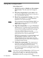
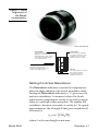
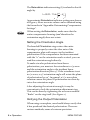
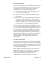
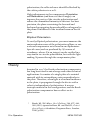
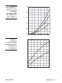
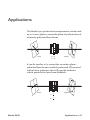
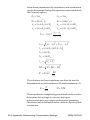
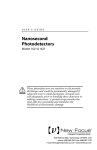
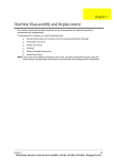
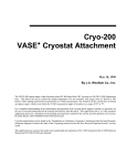
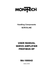
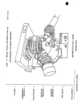
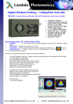
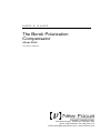
USER’S GUIDE The Berek Polarization Compensator Model 5540 U.S. Patent # 5,245,478 3635 Peterson Way • Santa Clara, CA 95054 • USA phone: (408) 980-5903 • fax: (408) 987-3178 e-mail: [email protected] • www.newfocus.com Warranty Newport Corporation guarantees its products to be free of defects for one year from the date of shipment. This is in lieu of all other guarantees, expressed or implied, and does not cover incidental or consequential loss. Information in this document is subject to change without notice. Copyright 2012, 2001-1998, Newport Corporation. All rights reserved. The New Focus logo and symbol are registered trademarks of Newport Corporation Document Number 554000 Rev. C Contents Operation 5 Introduction . . . . . . . . . . . . . . . . . . . . . . . . . . . . . . . . .5 Using the Compensator . . . . . . . . . . . . . . . . . . . . . . . .6 Theory . . . . . . . . . . . . . . . . . . . . . . . . . . . . . . . . . . . .10 Applications 15 Characteristics 17 Compensator Characteristics . . . . . . . . . . . . . . . . . . .17 Customer Service 19 Technical Support . . . . . . . . . . . . . . . . . . . . . . . . . . .19 Service. . . . . . . . . . . . . . . . . . . . . . . . . . . . . . . . . . . .19 Appendix I: Determining Compensator Settings Model 5540 21 Contents • 3 4 • Contents NEW FOCUS Operation Introduction The Model 5540 Berek polarization compensator can convert the polarization of a collimated laser beam from any state to any other state with the flexibility and precision previously characteristic only of expensive and lossy Soleil-Babinet compensators. Used as a variable waveplate, the Berek compensator can impose 1/4-wave or 1/2wave retardance at any wavelength between 200 nm and 1600 nm, dramatically reducing the number of different plates necessary in the laboratory. The Model 5540 polarization compensator can fit in a variety of 2" mirror mounts, or you can mount it directly to a post. With its 10-mm aperture, this compensator will accept beams from almost any commercially available laser system. Model 5540 Operation • 5 Using the Compensator Initial Alignment 1. Set the Retardation indicator on the compensator to zero. This also sets the tilt angle to zero. 2. Place the compensator in your setup. Make sure that the collimated laser beam is centered on the 12-mm diameter aperture. 3. Mount the compensator housing. It should be mounted such that the “0” on the Orientation indicator is at a convenient angle. We recommend mounting the Model 5540 in a gimbal-type mirror mount such as the Model 9852 shown in Figure 1. 4. Align the compensator. Leaving the Retardation indicator set to “0”, use the two tilt controls of the mirror mount to align the compensator so that it is normal to the propagation direction of the light. To do this, find the reflection from the compensator plate and force it to propagate back along the direction of the incident beam. When the compensator is properly aligned and the Retardation indicator is set to “0”, the reflected beam will not move away from the incident beam direction when the compensator is rotated around its axis. 5. Rotate the compensator. The compensator is rotated by turning the Orientation knurled ring. When the initial alignment has been done properly, the polarization compensator transmits the incident polarization unchanged, whatever the orientation angle. The indicator setting for Retardation is NOT the actual value of the tilt angle. See “Appendix: Determining Compensator Settings” for the relationship between Retardation indicator setting and tilt angle. 6 • Operation NEW FOCUS Figure 1: Initial alignment of the Berek compensator Patent #5,245,478 “Orientation” This ring controls the tilt angle. (See Appendix 1 for the relationship between tilt angle and the settings of this indicator.) Set this control to zero for initial alignment. This ring rotates the waveplate. It is usually convenient to set the waveplate so the zero for this control is horizontal or vertical. 3 60 “Retardation” 40 0 2 0 0 2 1 20 2 RETARDATION SEE MANUAL 320 16 BRAKE 15 “Brake” 300 ORIENTATION 340 17 To align the compensator, force the light reflecting back from the compensator to propagate along the direction of the incident beam. This setscrew locks the orientation ring to prevent accidental re-adjustment after the compensator has been set. Setting the Actual Retardance The Retardation indicator controls the compensator plate tilt angle and hence the actual retardance value. Setting the Retardation indicator to “0” gives zero tilt and zero retardance. At nonzero values, the Berek polarization compensator can be set to either a singleorder or a multiple-order waveplate. The smaller the retardance, the more accurately it can be set. To a good approximation, the tilt angle R that gives retardance R (in waves) is ( θ R ≅ sin −1 0.284 λR ) where is the wavelength in microns. Model 5540 Operation • 7 The Retardation indicator setting (I) is related to the tilt angle by π I = 50.22 - 71sin − θ R 4 π 1 50 22 - I Approximate Retardation indicator settings are shown in Figure 3. More accurate values can be obtained using the formulas in “Appendix: Determining Compensator Settings”. When setting the Retardation, make sure that the entire compensator housing (and therefore the orientation angle) does not rotate. Setting the Orientation Angle The knurled Orientation ring rotates the entire housing to properly orient the slow axis of the compensator plate with respect to the incident polarization. If the compensator has been mounted with the “0” on the orientation scale vertical, you can read the orientation angle directly. To make circular polarization from linear polarization, you must set the retardance to 1/4 wave and the orientation angle to the incident linear polarization direction plus 45°. If the retardance is set to 1/2 wave, a 45° orientation angle will rotate the plane of polarization by 90°. In general, a /2-wave plate rotation causes the plane of polarization to rotate by twice the orientation angle. After adjusting the orientation angle, it may be convenient to lock the orientation adjustment ring. This can be done by tightening the set screw marked “Brake” on the ring itself. (See Figure 1.) Verifying the Output Polarization When using a waveplate, one should always verify that it has produced the desired polarization. There are various methods, some of extreme precision. 8 • Operation NEW FOCUS Linear Polarization Since linear polarization can be blocked to better than 0.01% with a calcite polarizer, it is easy to verify that the output of the Model 5540 Berek polarization compensator is linear and oriented properly. 1. Place a calcite polarizer, such as a Model 5524 or 5525, after the compensator. 2. Orient the polarizer to block the desired output polarization. 3. Fine-tune the polarization. Both the tilt angle (see “Setting the Actual Retardance” on page 7) and orientation angle of the compensator can be used to do this. At this stage, do not use the mounting to adjust the tilt of the compensator housing. If the laser beam is not perfectly collimated, you may see a narrow absolutely dark line through the center of a very dim beam transmitted through the polarizer. If too much light is transmitted through the polarizer, even when tilt and orientation have been optimized, consider reducing the retardance by one full wave or improving the collimation. The smaller the retardance, the less sensitive is the polarization to imperfect collimation due to the angular dependence of the birefringence. Circular Polarization To verify circular polarization, reflect the output light back through the compensator. The polarization of the wave that goes through the compensator twice will be exactly orthogonal to the incident polarization for the circularly-polarized light. If the incident polarization is linear, this can best be achieved by setting a calcite polarizer in front of the Model 5540 polarization compensator oriented to transmit the incident beam perfectly. If the compensator is set to produce perfect circular Model 5540 Operation • 9 polarization, the reflected wave should be blocked by the calcite polarizer to 0.01%. Slight adjustments to the compensator Orientation and Retardation (and hence to the tilt angle) can improve the purity of the circular polarization and reduce the transmitted intensity in this test. For best precision, the plane containing the forward and backward propagating beams should be orthogonal to the plane of incidence of the incident beam on the tilt plate. Elliptical Polarization To verify elliptical polarization, you must measure the major and minor axes of the polarization ellipse, or use a second compensator as is found in an ellipsometer. Special cases (such as produced by N/2 waves of retardance, where N is an integer) can be verified in a way similar to circular polarization, but with the light making N passes through the compensator plate. Theory Invented in 1913,* the Berek polarization compensator has long been used in microscopy and other technical applications. It consists of a single plate of a uniaxial material with its extraordinary axis perpendicular to the plate. Therefore, when light is at normal incidence to the plate, it propagates through the device with a velocity independent of polarization. It sees an isotropic material in this configuration, and the Berek polarization compensator has no effect on its polarization. * 10 • Operation Berek, M., Zbl. Miner. Geol. Paläont. 388, 427, 464, 580 (1913) (quoted in Born, M. and Wolf, E., Principles of Optics, 6th edition, Pergamon Press, London, 1980, p.694.) NEW FOCUS However, when the plate is tilted with respect to the direction of the incident light, the plane of incidence becomes the plane of the extraordinary index of refraction. Light polarized in this plane propagates at a different velocity. The wave is slowed or retarded by an amount that depends on the angle of tilt and on the wavelength. Light in the polarization perpendicular to the plane of incidence continues to propagate as an ordinary wave with velocity independent of tilt angle. Thus, the light in the two planes of polarization accumulates a relative phase shift or retardance. For example, Figure 2 shows the slow axis being retarded by 90° relative to the fast axis resulting in linearly polarized light being converted to circularly polarized light when the device is oriented at 0°. Figure 2: Conversion of linearly polarized to circularly polarized light A. Linearly polarized light at the input of the Berek compensator B. Circular polarization at the output of the Berek compensator when the retardance is tuned to 90° Model 5540 Operation • 11 The Model 5540 Berek compensator allows the retardance and the orientation of the plane of incidence to be adjusted conveniently and independently using two knurled rings, one on each end of the housing. Once the tilt angle is set correctly with the Retardation knob, rotating the housing with the Orientation knob rotates the variable wave plate just like a conventional compensator or retarder. Precision scales allow both tilt angle and orientation angle to be set accurately. The axis of rotation for the plane of incidence can be conveniently set parallel to the propagation direction using a conventional optic mount. Near normal incidence, the retardance increases quadratically with tilt angle, allowing very precise compensation of small phase shifts due to other optical elements. Figure 3 shows the actual retardance versus the Retardation indicator setting for the New Focus Berek compensator at 488 nm, 632.8 nm, and 1060 nm. Figure 4 shows Retardation indicator setting versus wavelength to achieve precise /2 and /4 retardance. For an in-depth discussion on calculating these curves, see “Appendix: Determining Compensator Settings”. It contains the equations necessary to determine the actual retardance required to convert an arbitrary input polarization state into a specified output polarization state. It also contains both the exact expression for actual retardance versus Retardation indicator setting and the relationship between tilt angle and Retardation indicator setting. 12 • Operation NEW FOCUS Figure 3: Retardance (in waves) versus indicator setting at 488 nm, 632.8 nm, and 1060 nm 2.50 2.00 488 nm 1.50 1.00 632.8 nm 0.50 1060 nm 0.00 0.0 Figure 4: Indicator setting versus wavelength for /2 and /4 retardance 5.0 10.0 15.0 15 λ − 2 13 11 9 λ − 4 7 5 3 0.4 Model 5540 0.8 1.2 1.6 Operation • 13 14 • Operation NEW FOCUS Applications The Model 5540 polarization compensator can be used as a 1/2-wave plate to rotate the plane of polarization of a linearly-polarized laser beam. input Γ =π θ=0 output It can be used as a 1/4-wave plate to make a planepolarized laser beam circularly polarized. When used with a linear polarizer, this will provide isolation which protects the laser from feedback. input π 2 π θ= 4 output Γ= Model 5540 Applications • 15 3 60 By placing a linear polarizer after the Berek compensator, you can conveniently vary the attenuation of a beam without changing its polarization. 40 0 2 0 0 2 1 20 2 RETARDATION SEE MANUAL 300 15 input 320 16 ORIENTATION 340 17 Iout = = varies 0 output --2 --4 polarizer 3 60 By varying the retardance and orientation, you can produce arbitrary states of elliptical polarization which is especially useful in spectroscopy. 40 0 2 0 0 2 1 20 2 RETARDATION SEE MANUAL 15 320 300 16 ORIENTATION 340 17 input output = User Defined = User Defined 16 • Applications NEW FOCUS Characteristics Compensator Characteristics Model # 5540 Wavelength Range Clear Aperture Wavefront Distortion Model 5540 200–1600 nm 10 mm <1/8 wave Retardance 0–5.8 @ 300 nm 0– @ 1600 nm Resolution 0.001 wave @ null 0.01 wave @ 2 Characteristics • 17 18 • Characteristics NEW FOCUS Customer Service Technical Support Information and advice about the operation of any New Focus product is available from our applications engineers. For quickest response, ask for “Technical Support” and know the model and serial numbers for your product. Hours: 8:00–5:00 PST, Monday through Friday (excluding holidays). Toll Free: 1-866-NUFOCUS (1-866-683-6287) (from the USA & Canada only) Phone: (408) 980-5903 Support is also available by fax and email: Fax: (408) 987-3178 Email: [email protected] We typically respond to faxes and email within one business day. Service In the event that the compensator malfunctions or becomes damaged, please contact New Focus for a return authorization number and instructions on shipping the unit back for evaluation and repair. Model 5540 Customer Service • 19 20 • Customer Service NEW FOCUS Appendix: Determining Compensator Settings The most general application which uses a compensator is one in which the input and desired output polarization states are known and the compensator settings need to be determined. The actual desired retardance and orientation angle can be determined in a straightforward manner by first defining the input and output states in terms of the ellipticity (=minor axis a/major axis b) and the orientation of the major axis in the lab frame. Figure 5: Arbitrary elliptically polarized light can be defined in terms of and Model 5540 a α b ε=a/b Appendix: Determining Compensator Settings • 21 From these parameters the retardance and orientation can be determined using the equations associated with the Poincaré sphere: A1 = 2α 1 A 2 = 2α 2 -1 -1 E1 = 2tan ε1 E2 = 2tan ε 2 x1 = cos A1 cos E1 x 2 = cos A2 cos E2 y1 = sin A1cos E1 y 2 = sin A2 cos E2 x - x k = - tan-1 y2 - y1 2 1 ( x2 - x1)2 + ( y2 - y1)2 I 1 = cosA1 sin ( k - A1) L= h1 = sinE1 h2 = sinE2 2 2 I 2 = h 1 + I1 M = L2 + (h2 − h1) -1 Γ = 2sin 2 M 2 I2 The solutions to these equations can then be used to determine the actual retardance (R ) and orientation (Z ). R= Γ 2π Z= 05 . k These results are completely general and can be used to determine the settings to convert any input polarization into any output polarization assuming the states can be defined in terms of their ellipticity and orientation. 22 • Appendix: Determining Compensator Settings NEW FOCUS The relationship between retardance (R) and tilt angle can be determined from the angular dependence of the birefringence in MgF2. The extraordinary index of refraction, as seen by the optical beam, is given by where R is the tilt angle and no and ne are the indices of refraction. These are, in general, wavelength dependent and their dispersion relations are given by* Thus, the retardance R (in waves) is related to the tilt angle by The relationship between tilt angle (R) and Retardation indicator setting ( I ) is given by θR = 50.22 - I π - sin - 1 71 4 or I = 50.22 - 71sin * Model 5540 π −θR 4 Dodge, M., Appl. Opt. 23,12 1980-85 (1984) Appendix: Determining Compensator Settings • 23 24 • Appendix: Determining Compensator Settings NEW FOCUS