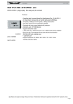
1
User Manual IDK-2131WN-K2HDA1E Copyright The documentation and the software included with this product are copyrighted 2012 by Advantech Co., Ltd. All rights are reserved. Advantech Co., Ltd. reserves the right to make improvements in the products described in this manual at any time without notice. No part of this manual may be reproduced, copied, translated or transmitted in any form or by any means without the prior written permission of Advantech Co., Ltd. Information provided in this manual is intended to be accurate and reliable. However, Advantech Co., Ltd. assumes no responsibility for its use, nor for any infringements of the rights of third parties, which may result from its use. Acknowledgements Intel and Pentium are trademarks of Intel Corporation. Microsoft Windows and MS-DOS are registered trademarks of Microsoft Corp. All other product names or trademarks are properties of their respective owners. Part No. 2006213100 Edition 1 Printed in Taiwan April 2012 IDK-2131WN-K2HDA1E User Manual ii A Message to the Customer Advantech Customer Services Each and every Advantech product is built to the most exacting specifications to ensure reliable performance in the harsh and demanding conditions typical of industrial environments. Whether your new Advantech equipment is destined for the laboratory or the factory floor, you can be assured that your product will provide the reliability and ease of operation for which the name Advantech has come to be known. Your satisfaction is our primary concern. Here is a guide to Advantech’s customer services. To ensure you get the full benefit of our services, please follow the instructions below carefully. Technical Support We want you to get the maximum performance from your products. So if you run into technical difficulties, we are here to help. For the most frequently asked questions, you can easily find answers in your product documentation. These answers are normally a lot more detailed than the ones we can give over the phone. So please consult this manual first. If you still cannot find the answer, gather all the information or questions that apply to your problem, and with the product close at hand, call your dealer. Our dealers are well trained and ready to give you the support you need to get the most from your Advantech products. In fact, most problems reported are minor and are able to be easily solved over the phone. In addition, free technical support is available from Advantech engineers every business day. We are always ready to give advice on application requirements or specific information on the installation and operation of any of our products. iii IDK-2131WN-K2HDA1E User Manual Product Warranty (2 years) Advantech warrants to you, the original purchaser, that each of its products will be free from defects in materials and workmanship for two years from the date of purchase. This warranty does not apply to any products which have been repaired or altered by persons other than repair personnel authorized by Advantech, or which have been subject to misuse, abuse, accident or improper installation. Advantech assumes no liability under the terms of this warranty as a consequence of such events. Because of Advantech’s high quality-control standards and rigorous testing, most of our customers never need to use our repair service. If an Advantech product is defective, it will be repaired or replaced at no charge during the warranty period. For outof-warranty repairs, you will be billed according to the cost of replacement materials, service time and freight. Please consult your dealer for more details. If you think you have a defective product, follow these steps: 1. Collect all the information about the problem encountered. (For example, CPU speed, Advantech products used, other hardware and software used, etc.) Note anything abnormal and list any onscreen messages you get when the problem occurs. 2. Call your dealer and describe the problem. Please have your manual, product, and any helpful information readily available. 3. If your product is diagnosed as defective, obtain an RMA (return merchandize authorization) number from your dealer. This allows us to process your return more quickly. 4. Carefully pack the defective product, a fully-completed Repair and Replacement Order Card and a photocopy proof of purchase date (such as your sales receipt) in a shippable container. A product returned without proof of the purchase date is not eligible for warranty service. 5. Write the RMA number visibly on the outside of the package and ship it prepaid to your dealer. IDK-2131WN-K2HDA1E User Manual iv Contents Chapter Chapter 1 Handling Precautions..........................1 1.1 Handling Precautions ................................................................................ 2 2 Overview...............................................3 2.1 2.2 General Description .................................................................................. 4 Display Characteristics.............................................................................. 4 Table 2.1: Display Characteristics ............................................... 4 Optical Characteristics .............................................................................. 5 Table 2.2: Optical Characteristics................................................ 5 2.3 Chapter Chapter Chapter Chapter 3 Functional Block Diagram ..................9 3.1 Functional Block Diagram ....................................................................... 10 Figure 3.1 Functional Block Diagram......................................... 10 4 Absolute Maximum Ratings .............11 4.1 Absolute Maximum Ratings .................................................................... 12 4.1.1 Absolute Ratings of TFT LCD Module ........................................ 12 4.1.2 Absolute Ratings of Backlight Unit.............................................. 12 4.1.3 Absolute Ratings of Environment................................................ 12 5 Electrical Characteristics..................13 5.1 5.2 Power Specification................................................................................. 14 5.1.1 Signal Electrical Characteristics.................................................. 14 Backlight Driving Conditions ................................................................... 16 6 Signal Characteristic .........................17 6.1 6.2 6.5 Pixel Format Image ................................................................................. 18 Signal Description ................................................................................... 19 Table 6.1: Signal Description..................................................... 19 The Input Data Format ............................................................................ 20 Interface Timing ...................................................................................... 20 6.4.1 Timing Characteristics ................................................................ 20 6.4.2 Input Timing Diagram.................................................................. 21 Power ON/OFF Sequence ...................................................................... 21 7 Connector & Pin Assignment ...........23 7.1 Connector & Pin Assignment .................................................................. 24 7.1.1 TFT LCD Module ........................................................................ 24 7.1.2 Backlight Unit .............................................................................. 25 8 Mechanical Characteristics ..............27 6.3 6.4 Chapter Chapter v IDK-2131WN-K2HDA1E User Manual Chapter 8.1 Mechanical Characteristics ..................................................................... 28 Figure 8.1 Front Side................................................................. 28 Figure 8.2 Rear Side ................................................................. 28 9 LED Backlight Driver Board............. 29 9.1 9.2 Features.................................................................................................. 30 Specifications.......................................................................................... 30 Table 9.1: Specification ............................................................. 30 Dimension ............................................................................................... 31 Connector and Pin Assignment .............................................................. 31 9.4.1 Input Connector & Pin Assignment............................................. 31 9.4.2 Output Connector & Pin Assignment .......................................... 32 Efficiency Test Report............................................................................. 32 Input/Output Connector SPEC................................................................ 33 9.3 9.4 9.5 9.6 IDK-2131WN-K2HDA1E User Manual vi Chapter 1 1 Handling Precautions 1.1 Handling Precautions 1. 2. Since front polarizer is easily damaged, pay attention not to scratch it. Be sure to turn off the power supply when inserting or disconnecting from the input connector. 3. Wipe off water drops immediately. Long contact with water may cause discoloration or spots. 4. When the panel surface is soiled, wipe it with absorbent cotton or other soft cloths. 5. Since the panel is made of glass, it may break or crack if dropped or bumped on a hard surface. 6. Since a CMOS LSI is used in this module, take care with static electricity and ensure you are earthed when handling. 7. Do not open or modify the module assembly. 8. Do not press the reflector sheet at the back of the module. 9. In case a module has to be put back into the packing container slot after it was removed, please press the far ends of the LED light bar reflector softly, otherwise the TFT module may get damaged. 10. At the insertion or removal of the Signal Interface Connector, be sure not to rotate nor tilt it. 11. After installation of the TFT Module into an enclosure, no bending or twisting forces should applied to the TFT Module. 12. Small amount of materials having no flammability grade are used in the LCD module. The LCD module should be supplied by power that complies with requirements of Limited Power Source (IEC60950 or UL1950). IDK-2131WN-K2HDA1E User Manual 2 Chapter 2 Overview 2 2.1 General Description IDK-2131WN-K2HDA1E is a Color Active Matrix Liquid Crystal Display composed of a TFT-LCD panel, a driver circuit, and backlight system. The screen format is intended to support the 1366x768 HD-WIDE mode (Non-interlace) screen. Each pixel is divided into Red, Green and Blue sub-pixels or dots which are arranged in vertical stripes. Gray scale or the brightness of the sub-pixel color is determined with a 8-bit gray scale signal for each dot. It has been designed to apply the 8-bit 1 channel LVDS interface method. It is intended to support displays where high brightness, wide viewing angle, high color saturation, and high color depth are very important.. All input signals are LVDS interface compatible. Driver board of backlight is included. 2.2 Display Characteristics The following items are characteristics summary on the table under 25°C condition: Table 2.1: Display Characteristics Items Unit Specifications Screen Diagonal [inch] 31.5 Active Area [mm] Pixels H x V 697.685 (H) x 392.256 (V) 1366x3 (RGB) x 768 Pixel Pitch [mm] Pixel Arrangement 0.51075 R.G.B. vertical stripe Display Mode Normally Black Nominal Input Voltage VDD [Volt] 12.0 (typ.) Typical Power Consumption [Watt] 56.6(PDD=3.6W +PLED=53W) LED driver board Power Consumption [Watt] 5.3 (90% efficiency) Weight [Grams] 7000 (typ.) Physical Size [mm] 760.0 (W) x 450.0 (H) x 46.9 (D) (with driver) Electrical Interface One Channel LVDS Surface Treatment Anti-Glare, 3H(Haze=11%) Support Color 16.7 M, 8 bit Temperature Range Operating Storage (Non-Operating) [°C] [°C] RoHS Compliance IDK-2131WN-K2HDA1E User Manual 0 to +50 -20 to +60 RoHS Compliance 4 The optical characteristics are measured under stable conditions at 25°C (Room Temperature): Table 2.2: Optical Characteristics Item Luminance Uniformity Optical Response Time [degree] [%] [msec] Color/Chromaticity Coordinates (CIE 1931) Conditions Min. Typ. Max. Note Horizontal (Right) CR = 10 (Left) 89 89 - Vertical (Upper) CR = 10 (Down) 89 89 - 1 9 Points 75 80 2, 3 Rising - - - Falling - - - Rising + Falling - 6.5 - White x White y - 0.3160 0.3530 - 5 4 Color Temp. K 6000 6500 White Luminance [cd/m2 ] 1100 1200 - 4 - - 4 Contrast Ratio 3000 4 Optical Equipment: BM-7, DT-100 or equivalent. 5 IDK-2131WN-K2HDA1E User Manual Overview Viewing Angle Unit Chapter 2 2.3 Optical Characteristics Note1! Definition of viewing angle. Viewing angle is the measurement of contrast ratio ≥10, at the screen center, over a 180()° horizontal and 180° vertical range (off-normal viewing angles). The 180° viewing angle range is broken down as below: 90° (θ)° horizontal left and right, and 90° (φ) vertical high (up) and low (down). The measurement direction is typically perpendicular to the display surface with the screen rotated to its center to develop the desired measurement viewing angle. Note2! 9 points position. 90 % 50 % 10 % 10 % 50 % 90 % Note3! The luminance uniformity of 9 points is defined by dividing the maximum luminance values by the minimum test point luminance. Minimum Brightness of nine points W9 IDK-2131WN-K2HDA1E User Manual = Maximum Brightness of nine points 6 Note5! Definition of response time: The output signals of the photo detector are measured when the input signals are changed from “Full Black” to “Full White” (rising time), and from “Full White” to “Full Black“ (falling time), respectively. The response time is the interval between the 10% and 90% of amplitudes. Please refer to the figure below. Overview Measurement method. The LCD module should be stabilized at a given temperature for 30 minutes to avoid abrupt temperature change during measurement. In order to stabilize the luminance, the measurement should be executed after the backlight has been lit for 30 minutes in a stable, windless and dark room. Optical Equipment: DT-100 or equivalent. Chapter 2 Note4! % Tf Tr 100 90 Optical White Black White response 10 0 7 IDK-2131WN-K2HDA1E User Manual IDK-2131WN-K2HDA1E User Manual 8 Chapter 3 Functional Block Diagram 3 3.1 Functional Block Diagram The following diagram shows the functional block of the 31.5 inches Color TFT-LCD Module: Figure 3.1 Functional Block Diagram IDK-2131WN-K2HDA1E User Manual 10 Chapter 4 4 Absolute Maximum Ratings 4.1 Absolute Maximum Ratings Absolute maximum ratings of the module is as following: 4.1.1 Absolute Ratings of TFT LCD Module Item Symbol Min. Max. Unit Conditions Logic/LCD Drive Voltage VCC -0.3 +13.5 [Volt] Note 1, 2 4.1.2 Absolute Ratings of Backlight Unit Item Symbol Min. Max. Unit Conditions LED BLU Current ILed - 450*7 [mA] Note 1, 2 Conditions 4.1.3 Absolute Ratings of Environment Item Symbol Min. Max. Unit Operating Temperature TOP 0 +50 [°C] Operation Humidity HOP 10 90 [%RH] Storage Temperature TST -20 +60 [°C] Storage Humidity HST 10 90 [%RH] Note 3 Note1! With in Ta= 25°C. Note2! Permanent damage to the device may occur if maximum values are exceeded. Note3! For quality performance, please refer to AUO IIS (Incoming Inspection Standard). IDK-2131WN-K2HDA1E User Manual 12 Chapter 5 Electrical Characteristics 5 5.1 Power Specification Input power specifications are as follows: Symbol Parameter Min. Typ. Max. Unit Condition Vcc Logic/LCD Drive Voltage 10.8 12.0 13.5 [Volt] IDD Input Current - 300 400 [mA] PDD VDD Power - 3.6 4.32 [Watt] IRush Inrush Current - -2.0 3.0 [A] Note 1 Note1! Duration:50 msec. Note2! Maximum wet bulb should be 39°C and no condensation. The relative humidity must not exceed 90% non-condensing at temperatures of 40°C or less. At temperatures greater than 40 °C, the wet bulb temperature must not exceed 39 °C. Note3! Surface temperature is measured at 50°C dry condition. 5.1.1 Signal Electrical Characteristics Input signals shall be low or Hi-Z state when VDD is off. Symbol Parameter Min. Typ. Max. Unit VTH Differential Input High Threshold - VTL Differential Input Low Threshold -100 - VICM Differential Input Common Mode Voltage 1.1 IDK-2131WN-K2HDA1E User Manual 14 - Condition +100 [mV] Note 1 - 1.25 1.4 [mV] Note 1 [V] Note 1 1. 2. 4. VICM=1.25 V. 5. Input Channel Pair Skew Margin. 6. Do not attach a conducting tape to the lamp connecting wire. If the lamp wire is attached to conducting tape, the TFT-LCD Module may have a low luminance and the inverter have abnormal action because current leakage occurs between the lamp wire and the conducting tape. The relative humidity must not exceed 80% non-condensing at temperature of 40°C or less. At temperatures greater than 40°C, the wet bulb temperature must not exceed 39°C. When operating at low temperatures, the brightness of the CCFL will drop and the life time of CGFL will be reduced. Specified values are for a single lamp only which is aligned horizontally. The lifetime is defined as the time which luminance of the lamp is 50% compared to its original value. [Operating condition: Continuous operating at Ta = 25 ±2°C] 7. 8. 15 IDK-2131WN-K2HDA1E User Manual Electrical Characteristics 3. The ripple voltage should be controlled under 10% of Vcc. Test Condition: (1) VDD=12.0V (2) Fv=60Hz (3) FCLK=82Mhz(Typ.) (4) Temperature=25° C (5) Test pattern: White Pattern Measurement condition: Rising time=400 us. Chapter 5 Note! 5.2 Backlight Driving Conditions Parameter guideline for LED Light Bar Driver is under stable conditions at 25°C (Room Temperature): Values Item Symbol Unit Conditions LED Voltage VL - 16.8 V Note 2 LED Current IL - 450*7 mA Note 3 LED lifetime - 50,000 - - Hr Note 1 Min. Typ. Max. Note1! The “LED lifetime” is defined as the module brightness decrease to 50% original brightness that the ambient temperature is 25°C and typical LED current at 7mA. Note2! The LED driving condition is defined for each LED module.(6 LED serial, a LED includes 1 chip). Note3! The variance of LED Light Bar power consumption is ±10%. Calculator value for reference (IL x VL = PLED). IDK-2131WN-K2HDA1E User Manual 16 Chapter 6 6 Signal Characteristic 6.1 Pixel Format Image Following figure shows the relationship between the input signal and LCD pixel format. IDK-2131WN-K2HDA1E User Manual 18 LVDS is a differential signal technology for LCD interface and high speed data transfer device. See Table 6.1 for the connector pin definitions. Table 6.1: Signal Description SIGNAL NAME DESCRIPTION 1 VCC +12V, DC, Regulated 2 VCC +12V, DC, Regulated 3 VCC +12V, DC, Regulated 4 VCC +12V, DC, Regulated 5 GND Ground and Signal Return 6 GND Ground and Signal Return 7 GND Ground and Signal Return 8 GND Ground and Signal Return 9 LVDS Option Open/High(3.3V) for NS, Low (GND) for JEIDA 10 Reserved NC(Aging) AUO internal test 11 GND Ground and Signal Return for LVDS 12 RIN0- LVDS Channel 0 negative 13 RIN0+ LVDS Channel 0 Positive 14 GND Ground and Signal Return for LVDS 15 RIN1- LVDS Channel 1 negative 16 RIN1+ LVDS Channel 1 Positive 17 GND Ground and Signal Return for LVDS 18 RIN2- LVDS Channel 2 negative 19 RIN2+ LVDS Channel 2 Positive 20 GND Ground and Signal Return for LVDS 21 RCLK- LVDS Clock negative 22 RCLK+ LVDS Clock Positive 23 GND Ground and Signal Return for LVDS 24 RIN3- LVDS Channel 3 negative 25 RIN3+ LVDS Channel 3 Positive 26 GND Ground and Signal Return for LVDS 27 Reserved NC (AUO internal) 28 Reserved NC (AUO internal) 29 GND Ground and Signal Return 30 GND Ground and Signal Return 19 IDK-2131WN-K2HDA1E User Manual Signal Characteristic PIN # Chapter 6 6.2 Signal Description 6.3 The Input Data Format Note! R/G/B data 7: MSB R/G/B data 0: LSB O = “First Pixel Data” E = “Second Pixel Data°” 6.4 Interface Timing 6.4.1 Timing Characteristics Item Symbol Min. Typ. Max. Unit Tclk 50 80 86 M Period Th 1460 1648 2000 Active Tdisp (V) Blanking Tblk (V) 94 282 634 Period Tv 784 810 1015 Active Tdisp (V) Blanking Tblk (V) Data CLK Horizontal Section Vertical Section Note! DE mode only. IDK-2131WN-K2HDA1E User Manual 20 1366 Tclk 1080 16 42 Th 247 Chapter 6 6.4.2 Input Timing Diagram VDD power and lamp on/off sequence is as follows. Interface signals are also shown in the chart. Signals from any system shall be Hi-Z state or low level when VDD is off. Power Sequence Timing Parameter Value Unit Min. Typ. Max. T1 0.4 - 30 T2 0.1 - - [ms] T3 200 - - [ms] T4 0*1 - - [ms] T5 0 - - [ms] [ms] T6 - - -*2 [ms] T7 500 - - [ms] Note! The values of the table follow PSWG. 21 IDK-2131WN-K2HDA1E User Manual Signal Characteristic 6.5 Power ON/OFF Sequence IDK-2131WN-K2HDA1E User Manual 22 Chapter 7 Connector & Pin Assignment 7 7.1 Connector & Pin Assignment These connectors are capable of accommodating the following signals. 7.1.1 TFT LCD Module 7.1.1.1 Connector Connector Name / Designation Interface Connector / Interface card Manufacturer Starconn Type Part Number 093G30-B0001A-1 Mating Housing Part Number FI-X30H 7.1.1.2 Pin Assignment Pin# Signal Name Pin# Signal Name 1 Vcc 2 Vcc 3 Vcc 4 Vcc 5 GND 6 GND 7 GND 8 GND 9 LVDS Option 10 Reserved 11 GND 12 RIN0- 13 RIN0+ 14 GND 15 RIN1- 16 RIN1+ 17 GND 18 RIN2- 19 RIN2+ 20 GND 21 RCLK- 22 RCLK+ 23 GND 24 RIN3- 25 RIN3+ 26 GND 27 Reserved 28 Reserved 29 GND 30 GND IDK-2131WN-K2HDA1E User Manual 24 These connectors are capable of accommodating the following signals. Connector Name / Designation LED Light Bar Connector / Backlight lamp Manufacturer TKP TERMINAL/ TKP HOVSING Type Part Number TKP TERMINAL 8820T/ TKP HOVSING 8821-03 Mating Type Part Number Wire VL 1007 24 AWG Connector No. Pin No. CN1 CN2 CN3 CN4 CN5 CN6 CN7 Input Color Function 1 GND Black Ground for backlight unit 2 HI Red Power supply for backlight unit 1 GND Black Ground for backlight unit 2 HI Red Power supply for backlight unit 1 GND Black Ground for backlight unit 2 HI Red Power supply for backlight unit 1 GND Black Ground for backlight unit 2 HI Red Power supply for backlight unit 1 GND Black Ground for backlight unit 2 HI Red Power supply for backlight unit 1 GND Black Ground for backlight unit 2 HI Red Power supply for backlight unit 1 GND Black Ground for backlight unit 2 HI Red Power supply for backlight unit 25 IDK-2131WN-K2HDA1E User Manual Connector & Pin Assignment 7.1.2.1 Signals for LED light bar connector Chapter 7 7.1.2 Backlight Unit IDK-2131WN-K2HDA1E User Manual 26 Chapter 8 Mechanical Characteristics 8 8.1 Mechanical Characteristics Figure 8.1 Front Side Figure 8.2 Rear Side IDK-2131WN-K2HDA1E User Manual 28 Chapter 9 9 LED Backlight Driver Board 9.1 Features 20 W x 7 port DC/DC LED Driver DC 20 ~ 28 V Input Voltage Range 0.5 A x 7port (max.) Constant Output Current 90% efficiency @ Input voltage 24 V, output 17 V / 750 mA PWM range: 0 ~ 100% 2 type output dimmer select: 0 ~ 100%, 5 ~ 100% 2 type input dimmer select: analog/digital 9.2 Specifications Table 9.1: Specification Symbol Characteristics Condition Min. Typ. Max. Unit Voltage Input Output 20 1 port output 1.5 20 W Voltage Input=24 V 10 20 V 90 Current 100 100mA ≤Iout ≤1000mA Note! % 1000 mA ±5 ±10 % OVP Thermal Shutdown ON/OFF Voltage V Power Protection Dimmer (Note) 28 Efficiency Current Accuracy Environment 24 Vin=24V Iout=750mA Vout=17V °C 165 Operation Junction Temperature 125 °C °C °C Operating Temperature -20 70 Storage Temperature -40 85 Dimmer Range 5 100 % Dimmer VH 2 5 V Dimmer VL 0 1.5 V Dimmer Frequency 0.25 0.5 1 KHz Von 3 5.5 V Voff 0 1.5 V When the input PWM signal, the high-level digital output must be greater than the total output level of only 5% of output. IDK-2131WN-K2HDA1E User Manual 30 Item Unit Specifications Physical Size [mm] 388.0 (W) x 63.0 (L) 9.4.1 Input Connector & Pin Assignment Red box on the map at [1] as input port, each pin is defined is as below (2.0 mm x 16 pin-SMD). Model name: WQC-106DRWR00D 1 VIN 2 VIN 3 VIN 4 VIN 5 VIN 6 VIN 7 VIN 8 GND 9 GND 10 GND 11 GND 12 GND 13 GND 14 ON/OFF 15 PWN in 16 Auto dimmer 31 IDK-2131WN-K2HDA1E User Manual LED Backlight Driver Board 9.4 Connector and Pin Assignment Chapter 9 9.3 Dimension 9.4.2 Output Connector & Pin Assignment Red box on the map at [2] as LED output connector, each pin is defined is as below (2.0 mm x 2 pin-SMD). Model name: WQC-106DRWR00D 1 VLED+ 2 VLED0- 9.5 Efficiency Test Report SET IOUT Vin(V) Lin(A) Vout(V) Iout(A) Efficiency 250mA 24.0 0.186 16 0.244 87.46 500mA 24.0 0.372 16.4 0.494 90.74 750mA 24.0 0.552 17 0.743 95.34 IDK-2131WN-K2HDA1E User Manual 32 Chapter 9 9.6 Input/Output Connector SPEC LED Backlight Driver Board 33 IDK-2131WN-K2HDA1E User Manual IDK-2131WN-K2HDA1E User Manual 34 www.advantech.com Please verify specifications before quoting. This guide is intended for reference purposes only. All product specifications are subject to change without notice. No part of this publication may be reproduced in any form or by any means, electronic, photocopying, recording or otherwise, without prior written permission of the publisher. All brand and product names are trademarks or registered trademarks of their respective companies. © Advantech Co., Ltd. 2012