1
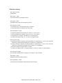
Specification
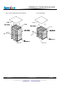
7" TFT
incl. 4-wire touch panel
Display:
Touch:
Part-No:
INNOLUX G070Y2-L01
DMC AST070A080A (tail to the left)
BT63189
Content:
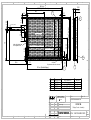
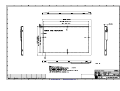
- Mechanical Drawing
- Appendix A: Specification of TFT
- Appendix B: Specification of touch panel
Please be aware that some of the values e.g. optical, mechanical etc.
of the complete unit (assembled display plus touch panel) might differ
from the original values of the individual components.
Version:
Note:
March 2014
This specification is subject to change without prior notice
1
2
3
4
5
6
7
8
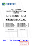
168,2 ±0,5
165 ±0,3 (Outline Touch)
A
11,06
83,3
2
2,4
A
1,4 ±0,2
2,1
78
10,5
152,4 ( A-A -Display+Touch)
154,9 (V-A-Touch)
C
2
2,05
C
B
104 ±0,3(Outline Touch)
3,8
104 ±0,3 (Outline Display)
108 ±0,5
Center of active area
55,32
16
1
B
Inside the dotted zone
do not press to seal.
93,94 ( V-A-Touch)
4
Contact (front)
91,44 (A-A-Display+Touch)
2,4
6,25
2
Air Vent
No pressure on the air vent area !
3,1
POS-NR.
1
2
3
4
E
BENENNUNG
BT 63170
TP02077
KT 71031
KT 71031
D
BESCHREIBUNG
Display
0,5 mm
First angle projection
2012
DRAWN
1
2
3
4
NAME
Schulz
DATE
27.06.
Rev.
1.0
MENGE
1
1
2
2
Touch TP02077
3 x 0,13 x 161
3 x 0,13 x 94
Tolerances not spezified
(Fehlende Freimaßtoleranzen)
F
1
1
165 ±0,3 (Outline Display)
D
3,55
80 ±1
4
3+4
Rev.: 1.0
M 1:1
Unit of measurement : mm
BT 63 189
MODIFICATION/DESCRIPTION
Neuanlage
DATA MODUL
CA-Link Nr.:
Display-Touch- Assembly
Z.Nr.: 1.0612.189.90.01.000
Conrac P/Nr.:
--
A3
Bl.1v.1
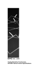
Specification
G070Y2-L01
17.8cm (7.0") / WVGA / LVDS / LED
Version: 2.4
Date: August 2011
Note: This specification is subject to change without prior notice
PRODUCT SPECIFICATION
Doc. Number :
□ Tentative Specification
□ Preliminary Specification
■ Approval Specification
MODEL NO.: G070Y2
SUFFIX: L01
Customer:
APPROVED BY
SIGNATURE
Name / Title
Note
Please return 1 copy for your confirmation with your
signature and comments.
核准時間
部門
審核
角色
投票
2011-08-24
16:09:06
APPL
產品管理處
yuhsiang.chang
(張喻翔/514-10922)
Director
Accept
Version 2.4
23 August 2011
The copyright belongs to CHIMEI InnoLux. Any unauthorized use is prohibited.
Data Modul AG - www.data-modul.com
1 / 28
PRODUCT SPECIFICATION
- CONTENTS REVISION HISTORY
-------------------------------------------------------
3
1. GENERAL DESCRIPTION
-------------------------------------------------------
4
-------------------------------------------------------
6
-------------------------------------------------------
8
-------------------------------------------------------
11
-------------------------------------------------------
12
-------------------------------------------------------
16
-------------------------------------------------------
19
-------------------------------------------------------
22
-------------------------------------------------------
23
1.1 OVERVIEW
1.2 FEATURES
1.3 APPLICATION
1.4 GENERAL SPECIFICATIONS
1.5 MECHANICAL SPECIFICATIONS
2. ABSOLUTE MAXIMUM RATINGS
2.1 ABSOLUTE RATINGS OF ENVIRONMENT
2.2 ELECTRICAL ABSOLUTE RATINGS
2.2.1 TFT LCD MODULE
2.2.2 LED CONVERTER
3. ELECTRICAL CHARACTERISTICS
3.1 RECOMMENDED OPERATIN CONDITION
3.2 BACKLIGHT UNIT
4. BLOCK DIAGRAM
4.1 TFT LCD MODULE
5. INPUT TERMINAL PIN ASSIGNMENT
5.1 LVDS I/O PIN ASSIGNMENT
5.2 BACKLIGHT PIN ASSIGNMENT
5.3 SCANNING DIRECTION
5.4 COLOR DATA INPUT ASSIGNMENT
6. INTERFACE TIMING
6.1 TIMING CHARACTERISTICS
6.2 LVDS INPUT DATA FORMAT
6.3 POWER ON/OFF SEQUENCE
7. OPTICAL CHARACTERISTICS
7.1 TEST CONDITIONS
7.2 OPTICAL SPECIFICATIONS
8. RELIABILITY TEST
8.1RELIABILITY TEST CONDITION
9. PACKAGING
10. DEFINTION OF LABELS
-------------------------------------------------------
25
11. PRECATIONS
--------------------------------------------------------
26
12. MECHANICAL CHARACTERISTICS
-------------------------------------------------------
27
Version 2.4
23 August 2011
The copyright belongs to CHIMEI InnoLux. Any unauthorized use is prohibited.
Data Modul AG - www.data-modul.com
2 / 28
PRODUCT SPECIFICATION
REVISION HISTORY
Version
Date
Section
Description
Ver 2.0 Oct. 30, ‘09
All
G070Y2-L01 Approval specification was first issued.
Ver 2.1 May.13, 10
1.4
Module Power Consumption from 3.56 W to 3.71 W
3.2
Converter Power Supply Current from 0.25A to 0.263mA
Converter Power Consumption from 3W to 3.15W
Note(2) IL = 60 mA(Per EA) change to IL = 55 mA(Per EA)
Ver 2.2 Sep. 9, 10
Ver 2.3 Dec. 1, 10
7.1
TEST CONDITIONS
Current from 60±4mA to 55±3mA
1.4
Module Power consumption 3.71W ->4.04W
3.1
Power Supply Current
3.2
Add Note(3)
6.1
Clock Frequency 1/Tclock:
White 140mA -> 250mA
Black 170mA -> 270mA
Min. 27 MHz -> 28 MHz
Max. 33 MHz -> 32MHz
Ver 2.4 Aug. 23, 10
2.2.2
3.2
Version 2.4
Enable Voltage Max. from 4 to 5
Backlight Adjust Max. from 3.3 to 5
EN Control Level / Backlight on max. from 3.3 to 5
PWM Control Level / PWM High Level max. from 3.3 to 5
PWM Control Duty Ratio min. from 20 to 10
PWM Control Frequency min. from 190 to 100
max. from 210 to 300
23 August 2011
The copyright belongs to CHIMEI InnoLux. Any unauthorized use is prohibited.
Data Modul AG - www.data-modul.com
3 / 28
PRODUCT SPECIFICATION
1. GENERAL DESCRIPTION
1.1 OVERVIEW
G070Y2-L01 is a 7inch TFT Liquid Crystal Display module with a LED backlight unit and a-20pin 6/8bit
LVDS interface controller board. The converter for the LED Backlight Unit is built in. This module
supports 800 (R.G.B )x 480 WVGA mode which main application is the automotive display and industrial
field.
1.2 FEATURES
- Wide viewing angle.
- Fast response time
- Wide operating temperature
- Reversible scan function
- 6/8 bit convertible
- High Color gamut ( NTSC:72% )
1.3 APPLICATION
- Automotive Display
- Industry Application
1.4 GENERAL SPECIFICATI0NS
Item
Diagonal Size
Active Area
Bezel Opening Area
Driver Element
Pixel Number
Pixel Pitch
Pixel Arrangement
Display Colors
Display Mode
Surface Treatment
Module Power Consumption
Specification
7
152.4x91.44
154.6x93.64
a-si TFT active matrix
800 x R.G.B. x 480
0.1905 x 0.1905
RGB vertical stripe
262k or 16.2M
Normal White
Anti-glare, Hard Coating ( 3H )
4.04
Unit
inch
mm
mm
pixel
mm
color
W
Note
(1)
(2)
Typ.
Note (1) Please refer to the attached drawings for more information of front and back outline dimensions.
Version 2.4
23 August 2011
The copyright belongs to CHIMEI InnoLux. Any unauthorized use is prohibited.
Data Modul AG - www.data-modul.com
4 / 28
PRODUCT SPECIFICATION
Note (2)
1.5 MECHANICAL SPECIFICATIONS
Item
Horizontal (H)
Module Size
Vertical (V)
Depth (D)
Weight
Min.
164.3
103.3
9.03
Typ.
165
104
9.53
147
Max.
165.3
104.3
10.03
162
Unit
mm
mm
mm
g
Note
(1)
Note (1) Please refer to the attached drawings for more information of front and back outline dimensions.
Version 2.4
23 August 2011
The copyright belongs to CHIMEI InnoLux. Any unauthorized use is prohibited.
Data Modul AG - www.data-modul.com
5 / 28
PRODUCT SPECIFICATION
2. ABSOLUTE MAXIMUM RATINGS
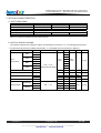
2.1 ABSOLUTE RATINGS OF ENVIRONMENT
Item
Value
Symbol
Operating Ambient Temperature
Storage Temperature
Min.
-30
-40
TOP
TST
Unit
Max.
+85
+95
Note
ºC
ºC
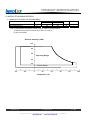
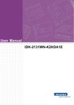
Note (1) Temperature and relative humidity range is shown in the figure below.
(2) Wet-bulb temperature should be 39 ºC Max. (Ta > 40 ºC).
(3) No condensation.
Relative Humidity (%RH)
100
80
60
Operating Range
40
20
Storage Range
-40
-20
0
20
40
60
80
100
Temperature (ºC)
Version 2.4
23 August 2011
The copyright belongs to CHIMEI InnoLux. Any unauthorized use is prohibited.
Data Modul AG - www.data-modul.com
6 / 28
PRODUCT SPECIFICATION
2.2 ELECTRICAL ABSOLUTE RATINGS
2.2.1 TFT LCD MODULE
Item
Ta = 25 ± 2 ºC
Symbol
Power Supply Voltage
Vcc
Value
Min.
-0.3
Max.
4
Unit
Note
V
(1)
2.2.2 LED CONVERTER
Item
Symbol
Converter Voltage
Enable Voltage
Backlight Adjust
Vi
EN
ADJ
Value
Min.
-0.3
-----
Max.
18
5
5
Unit
Note
V
V
V
(1) , (2)
Note (1) Permanent damage to the device may occur if maximum values are exceeded. Function operation
should be restricted to the conditions described under Normal Operating Conditions.
Note (2) Specified values are for LED converter (Refer to 3.2 for further information).
Version 2.4
23 August 2011
The copyright belongs to CHIMEI InnoLux. Any unauthorized use is prohibited.
Data Modul AG - www.data-modul.com
7 / 28
PRODUCT SPECIFICATION
3. ELECTRICAL CHARACTERISTICS
3.1 RECOMMENDED OPERATION CONDITION
Parameter
Symbol
Power Supply Voltage
Rush Current
Min.
3.0
Vcc
IRUSH
White
Black
LVDS Differential Input High Threshold
LVDS Differential Input Low Threshold
LVDS Common Mode Voltage
Ta = 25 ± 2 ºC
Value
Typ.
Max.
3.3
3.6
1.5
250
270
100
Power Supply Current
VTH(LVDS)
VTL(LVDS)
VCM
-100
1.2
Unit
Note
V
A
mA
mA
mV
mV
V
(1)
(2)
(3)a
(3)b
-
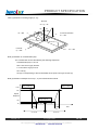
Note (1) The assembly should be always operated within above ranges.
Note (2) Measurement Conditions:
Vcc
Q1
2SK1475
Vcc
C3
FUSE
(LCD Module Input)
1uF
R1
47K
(High to Low)
(Control Signal)
Q2
R2
2SK1470
SW
1K
+12V
VR1
47K
C2
C1
0.01uF
1uF
Vcc rising time is 470µs
Vcc
0.9Vcc
0.1Vcc
GND
470µs
Version 2.4
23 August 2011
The copyright belongs to CHIMEI InnoLux. Any unauthorized use is prohibited.
Data Modul AG - www.data-modul.com
8 / 28
PRODUCT SPECIFICATION
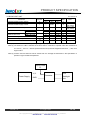
Note (3) The specified power supply current is under the conditions at Vcc = 3.3V , Ta = 25 ± 2 ºC, fv = 60
Hz, whereas a power dissipation check pattern below is displayed.
a. White Pattern
b. Black Pattern
Active Area
Active Area
Version 2.4
23 August 2011
The copyright belongs to CHIMEI InnoLux. Any unauthorized use is prohibited.
Data Modul AG - www.data-modul.com
9 / 28
PRODUCT SPECIFICATION
3.2 BACKLIGHT UNIT
Ta = 25 ± 2 ºC
Parameter
Symbol
Value
Typ.
12.0
Max.
13.2
Unit
Converter Power Supply Voltage
Vi
Min.
10.8
Converter Power Supply Current
Ii
---
0.263
---
A
PLED
---
3.15
---
W
---------
fPWM
2.0
0
2.0
0
10
100
5
0.8
5
0.15
100
300
V
V
V
V
%
Hz
LL
50,000
Converter Power Consumption
EN Control Level
PWM Control Level
Backlight on
Backlight off
PWM High Level
PWM Low Level
PWM Control Duty Ratio
PWM Control Frequency
LED Life Time
200
Note
V
@ Vi = 12V
(Duty 100%)
@ Vi = 12V
(Duty 100%)
Hrs
(2)
Note (1) LED current is measured by utilizing a high frequency current meter as shown below:
Note (2) The lifetime of LED is defined as the time when it continues to operate under the conditions at
Ta = 25 ±2 ℃ and ILED = 55mADC(LED forward current) until the brightness becomes ≦ 50% of its
original value.
Note (3) Please note that LED life will be shorter than the average life described in the specification if
operate in higher ambient temperature.
Input Power
Pi
Vi, Ii
Power Supply
Version 2.4
GND
Converter
LED
Backlight
Unit
23 August 2011
The copyright belongs to CHIMEI InnoLux. Any unauthorized use is prohibited.
Data Modul AG - www.data-modul.com
10 / 28
PRODUCT SPECIFICATION
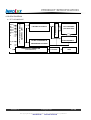
4. BLOCK DIAGRAM
4.1 TFT LCD MODULE
SCAN DRIVER IC
VCC_IN
INPUT CONNECTOR
(076B20-0048RA-G4,Starconn)
RX3(+/-)
FRC
RX2(+/-)
RXC(+/-)
RX1(+/-)
RX0(+/-)
LR
UD
LVDS Receiver INPUT
TFT LCD PANEL
(800x R.G.B.x480)
DATA DRIVER IC
DC/DC CONVERTER &
REFERENCE VOLTAGE
GND
Vi
Version 2.4
CONVERTER CONNECTOR
(LM123S004HTF13)
LED
Converter
LED BACKLIGHT
UNIT
23 August 2011
The copyright belongs to CHIMEI InnoLux. Any unauthorized use is prohibited.
Data Modul AG - www.data-modul.com
11 / 28
PRODUCT SPECIFICATION
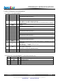
5. INPUT TERMINAL PIN ASSIGNMENT
5.1 LVDS I/O PIN ASSIGNMENT
Pin
Name
I/O
1
RX3+
I
2
RX3-
I
3
NC
I
4
FRC
I
5
GND
I
6
RXC+
I
7
RXC-
I
8
GND
I
9
RX2+
I
10
RX2-
I
11
GND
I
12
RX1+
I
13
RX1-
I
14
GND
I
15
RX0+
I
16
RX0-
I
Description
LVDS differential data input Pair 3.
No Connected
Dithering control setting
When FRC=H, the width of data input 8 bits
When FRC=L, the width of data input 6 bits and set Dx0 and Dx1 to logical low
(Default pull low)
Ground
LVDS differential Clock input Pair
Ground
LVDS differential data input Pair 2
Ground
LVDS differential data input Pair 1
Ground
LVDS differential data input Pair 0
19
VCC_IN
I
Shift direction of Source Driver IC internal shift register is controlled by this pin as
show below:
LR=H SO1Æ ……SO1200 (Default pull high)
LR=L SO1200Æ…….SO1
Gate Driver Up/down scan setting
When UD=H, reverse scan
When UD=L, normal scan (Default pull low)
Digital power supply (+3.3V)
20
VCC_IN
I
Digital power supply (+3.3V)
17
LR
I
18
UD
I
Note (1) User’s connector Part No.: 076B20-0048RA-G4,Starconn or equivalent
5.2 BACKLIGHT PIN ASSIGNMENT (Converter connector pin)
No
Symbol
I/O
1
2
3
4
Vi
ADJ
EN
VGND
I
I
I
Description
Converter input voltage
Backlight Adjust
Enable pin
Converter ground
Note (1) User’s connector Part No: LM123S004HTF13,4 PIN,UNE
Version 2.4
23 August 2011
The copyright belongs to CHIMEI InnoLux. Any unauthorized use is prohibited.
Data Modul AG - www.data-modul.com
12 / 28
PRODUCT SPECIFICATION
5.3 SCANNING DIRECTION
The following figures show the image see from the front view. The arrow indicates the direction of scan.
Fig.1 Normal Scan
Fig.2 Reverse Scan
Fig.3 Reverse Scan
Fig.4 Reverse Scan
Fig. 1 Normal scan ( pin 17, LR = High ; pin 18, UD = Low )
Fig. 2 Reverse scan ( pin 17, LR = Low ; pin 18, UD = Low )
Fig. 3 Reverse scan ( pin 17, LR = High ; pin 18, UD = High )
Fig. 4 Reverse scan ( pin 17, LR = Low ; pin 18, UD = High )
Version 2.4
23 August 2011
The copyright belongs to CHIMEI InnoLux. Any unauthorized use is prohibited.
Data Modul AG - www.data-modul.com
13 / 28
PRODUCT SPECIFICATION
5.4 COLOR DATA INPUT ASSIGNMENT
The brightness of each primary color (red, green and blue) is based on the 6-bit gray scale data input for
the color. The higher the binary input, the brighter the color. The table below provides the assignment of
color versus data input. ( 0: Low Level Voltage, 1: High Level Voltage)
Data Signal
Color
Basic
Colors
Gray
Scale
Of
Red
Gray
Scale
Of
Green
Gray
Scale
Of
Blue
Red
Green
Blue
R5
R4
R3
R2
R1
R0 G5
Black
Red
Green
Blue
Cyan
Magenta
Yellow
White
0
1
0
0
0
1
1
1
0
1
0
0
0
1
1
1
0
1
0
0
0
1
1
1
0
1
0
0
0
1
1
1
0
1
0
0
0
1
1
1
0
1
0
0
0
1
1
1
0
0
1
0
1
0
1
1
0
0
1
0
1
0
1
1
0
0
1
0
1
0
1
1
0
0
1
0
1
0
1
1
0
0
1
0
1
0
1
1
Red(0) / Dark
Red(1)
Red(2)
:
:
Red(61)
Red(62)
Red(63)
0
0
0
:
:
1
1
1
0
0
0
:
:
1
1
1
0
0
0
:
:
1
1
1
0
0
0
:
:
1
1
1
0
0
1
:
:
0
1
1
0
1
0
:
:
1
0
1
0
0
0
:
:
0
0
0
0
0
0
:
:
0
0
0
0
0
0
:
:
0
0
0
0
0
0
:
:
0
0
0
Green(0) / Dark
Green(1)
Green(2)
:
:
Green(61)
Green(62)
Green(63)
0
0
0
:
:
0
0
0
0
0
0
:
:
0
0
0
0
0
0
:
:
0
0
0
0
0
0
:
:
0
0
0
0
0
0
:
:
0
0
0
0
0
0
:
:
0
0
0
0
0
0
:
:
1
1
1
0
0
0
:
:
1
1
1
0
0
0
:
:
1
1
1
Blue(0) / Dark
Blue(1)
Blue(2)
:
:
Blue(61)
Blue(62)
Blue(63)
0
0
0
:
:
0
0
0
0
0
0
:
:
0
0
0
0
0
0
:
:
0
0
0
0
0
0
:
:
0
0
0
0
0
0
:
:
0
0
0
0
0
0
:
:
0
0
0
0
0
0
:
:
0
0
0
0
0
0
:
:
0
0
0
0
0
0
:
:
0
0
0
Version 2.4
G4 G3 G2 G1 G0
B5
B4
B3
B2
B1
B0
0
0
1
0
1
0
1
1
0
0
0
1
1
1
0
1
0
0
0
1
1
1
0
1
0
0
0
1
1
1
0
1
0
0
0
1
1
1
0
1
0
0
0
1
1
1
0
1
0
0
0
1
1
1
0
1
0
0
0
:
:
0
0
0
0
0
0
:
:
0
0
0
0
0
0
:
:
0
0
0
0
0
0
:
:
0
0
0
0
0
0
:
:
0
0
0
0
0
0
:
:
0
0
0
0
0
0
:
:
0
0
0
0
0
0
:
:
0
0
0
0
0
0
:
:
1
1
1
0
0
1
:
:
0
1
1
0
1
0
:
:
1
0
1
0
0
0
:
:
0
0
0
0
0
0
:
:
0
0
0
0
0
0
:
:
0
0
0
0
0
0
:
:
0
0
0
0
0
0
:
:
0
0
0
0
0
0
:
:
0
0
0
0
0
0
:
:
0
0
0
0
0
0
:
:
0
0
0
0
0
0
:
:
0
0
0
0
0
0
:
:
1
1
1
0
0
0
:
:
1
1
1
0
0
0
:
:
1
1
1
0
0
0
:
:
1
1
1
0
0
1
:
:
0
1
1
0
1
0
:
:
1
0
1
23 August 2011
The copyright belongs to CHIMEI InnoLux. Any unauthorized use is prohibited.
Data Modul AG - www.data-modul.com
14 / 28
PRODUCT SPECIFICATION
The brightness of each primary color (red, green and blue) is based on the 8-bit gray scale data input for the color.
The higher the binary input, the brighter the color. The table below provides the assignment of color versus data input.
( 0: Low Level Voltage, 1: High Level Voltage)
Data Signal
Color
Red
Green
Blue
R7 R6 R5 R4 R3 R2 R1 R0 G7 G6 G5 G4 G3 G2 G1 G0 B7 B6 B5 B4 B3 B2 B1 B0
Black
Red
Green
Blue
Basic Cyan
Colors Magenta
Yellow
White
0
1
0
0
0
1
1
1
0
1
0
0
0
1
1
1
0
1
0
0
0
1
1
1
0
1
0
0
0
1
1
1
0
1
0
0
0
1
1
1
0
1
0
0
0
1
1
1
0
1
0
0
0
1
1
1
0
1
0
0
0
1
1
1
0
0
1
0
1
0
1
1
0
0
1
0
1
0
1
1
0
0
1
0
1
0
1
1
0
0
1
0
1
0
1
1
0
0
1
0
1
0
1
1
0
0
1
0
1
0
1
1
0
0
1
0
1
0
1
1
0
0
1
0
1
0
1
1
0
0
0
1
1
1
0
1
0
0
0
1
1
1
0
1
0
0
0
1
1
1
0
1
0
0
0
1
1
1
0
1
0
0
0
1
1
1
0
1
0
0
0
1
1
1
0
1
0
0
0
1
1
1
0
1
0
0
0
1
1
1
0
1
Red(0) / Dark
Red(1)
Red(2)
:
Gray
:
Scale Red(253)
Of
Red(254)
Red Red(255)
0
0
0
:
:
1
1
1
0
0
0
:
:
1
1
1
0
0
0
:
:
1
1
1
0
0
0
:
:
1
1
1
0
0
0
:
:
1
1
1
0
0
0
:
:
1
1
1
0
0
1
:
:
0
1
1
0
1
0
:
:
1
0
1
0
0
0
:
:
0
0
0
0
0
0
:
:
0
0
0
0
0
0
:
:
0
0
0
0
0
0
:
:
0
0
0
0
0
0
:
:
0
0
0
0
0
0
:
:
0
0
0
0
0
0
:
:
0
0
0
0
0
0
:
:
0
0
0
0
0
0
:
:
0
0
0
0
0
0
:
:
0
0
0
0
0
0
:
:
0
0
0
0
0
0
:
:
0
0
0
0
0
0
:
:
0
0
0
0
0
0
:
:
0
0
0
0
0
0
:
:
0
0
0
0
0
0
:
:
0
0
0
Green(0)/ Dark
Green(1)
Green(2)
:
Gray
:
Scale
Green(253)
Of
Green Green(254)
Green(255)
0
0
0
:
:
0
0
0
0
0
0
:
:
0
0
0
0
0
0
:
:
0
0
0
0
0
0
:
:
0
0
0
0
0
0
:
:
0
0
0
0
0
0
:
:
0
0
0
0
0
0
:
:
0
0
0
0
0
0
:
:
0
0
0
0
0
0
:
:
1
1
1
0
0
0
:
:
1
1
1
0
0
0
:
:
1
1
1
0
0
0
:
:
1
1
1
0
0
0
:
:
1
1
1
0
0
0
:
:
1
1
1
0
0
1
:
:
0
1
1
0
1
0
:
:
1
0
1
0
0
0
:
:
0
0
0
0
0
0
:
:
0
0
0
0
0
0
:
:
0
0
0
0
0
0
:
:
0
0
0
0
0
0
:
:
0
0
0
0
0
0
:
:
0
0
0
0
0
0
:
:
0
0
0
0
0
0
:
:
0
0
0
Blue(0) / Dark
Blue(1)
Blue(2)
:
Gray
:
Scale
Blue(253)
Of
Blue Blue(254)
Blue(255)
0
0
0
:
:
0
0
0
0
0
0
:
:
0
0
0
0
0
0
:
:
0
0
0
0
0
0
:
:
0
0
0
0
0
0
:
:
0
0
0
0
0
0
:
:
0
0
0
0
0
0
:
:
0
0
0
0
0
0
:
:
0
0
0
0
0
0
:
:
0
0
0
0
0
0
:
:
0
0
0
0
0
0
:
:
0
0
0
0
0
0
:
:
0
0
0
0
0
0
:
:
0
0
0
0
0
0
:
:
0
0
0
0
0
0
:
:
0
0
0
0
0
0
:
:
0
0
0
0
0
0
:
:
1
1
1
0
0
0
:
:
1
1
1
0
0
0
:
:
1
1
1
0
0
0
:
:
1
1
1
0
0
0
:
:
1
1
1
0
0
0
:
:
1
1
1
0
0
1
:
:
0
1
1
0
1
0
:
:
1
0
1
Version 2.4
23 August 2011
The copyright belongs to CHIMEI InnoLux. Any unauthorized use is prohibited.
Data Modul AG - www.data-modul.com
15 / 28
PRODUCT SPECIFICATION
6. INTERFACE TIMING
6.1 TIMING CHARACTERISTICS
The input signal timing specifications are shown as the following table and timing diagram
Parameter
Symbol
Vertical Display
Value
Typ.
500
Max.
550
Unit
Period
Tv
Min.
490
Active
Blanking
Tvd
Tvb
10
480
20
70
Th
Th
Period
Th
930
992
1090
Tclock
Thd
Thb
1/Tclock
130
28
800
192
29.5
290
32
Tclock
Tclock
MHz
Horizontal Display
Active
Blanking
Clock Frequency
Th
Note
Tv=Tvd+Tvb
Th=Thd+Thb
-
Note (1) Since this assembly is operated in DE only mode, Hsync and Vsync input signals should be set to
low logic level. Otherwise, this assembly would operate abnormally.
(2) Frame rate is 60Hz
INPUT SIGNAL TIMING DIAGRAM
Version 2.4
23 August 2011
The copyright belongs to CHIMEI InnoLux. Any unauthorized use is prohibited.
Data Modul AG - www.data-modul.com
16 / 28
PRODUCT SPECIFICATION
6.2 LVDS INPUT DATA FORMAT
Note (1) R/G/B data 7: MSB, R/G/B data 0: LSB
Note (2) Please follow PSWG
Note (3) Output signals from any system shall be low or Hi-Z state when VCC is off.
Version 2.4
23 August 2011
The copyright belongs to CHIMEI InnoLux. Any unauthorized use is prohibited.
Data Modul AG - www.data-modul.com
17 / 28
PRODUCT SPECIFICATION
6.3 POWER ON/OFF SEQUENCE
To prevent a latch-up or DC operation of LCD assembly, the power on/off sequence should be as the diagram
below
0.9VCC
VCC
0.9VCC
90%
0.1VCC
0.1VCC
10%
T7
T1
T2
T3
VALID
LVDS
Vi
T4
0.9Vi
0.9Vi
0.1Vi
0.1Vi
T6
T5
90%
PWM DIMMING
10%
T8
T9
90%
BL
ON/OFF
10%
Power ON/OFF sequence
Note (1) Please avoid floating state of interface signal at invalid period.
Note (2) When the interface signal is invalid, be sure to pull down the power supply of LCD VCC to 0 V.
Note (3) The Backlight converter power must be turned on after the power supply for the logic and the interface
signal is valid. The Backlight converter power must be turned off before the power supply for the logic
and the interface signal is invalid.
Parameter
T1
T2
T3
T4
T5
T6
T7
T8
T9
Version 2.4
Min
0.5
0
0
500
20
10
5
10
10
Value
Typ
-
Max
10
50
50
300
-
Units
ms
ms
ms
ms
ms
ms
ms
ms
ms
23 August 2011
The copyright belongs to CHIMEI InnoLux. Any unauthorized use is prohibited.
Data Modul AG - www.data-modul.com
18 / 28
PRODUCT SPECIFICATION
7. OPTICAL CHARACTERISTICS
7.1 TEST CONDITIONS
Item
Ambient Temperature
Ambient Humidity
Supply Voltage
Input Signal
Current
Converter Duty
Symbol
Value
Unit
o
Ta
C
25±2
Ha
%RH
50±10
VCC
3.3
V
According to typical value in "3. ELECTRICAL CHARACTERISTICS"
If
mA
55±3
100
%
Note (1) If means the forward current of each channel
7.2 OPTICAL SPECIFICATIONS
The relative measurement methods of optical characteristics are shown in 7.2. The following items should
be measured under the test conditions described in 7.1 and stable environment shown in Note (6).
Item
Red
Color
Chromaticity
Green
Blue
White
Symbol
Rx
Condition
Min.
Typ.
0.645
Ry
0.341
Gx
Gy
Bx
0.312
0.625
0.153
By
Wx
Wy
Typ –
0.03
Max.
Unit
Typ +
0.03
Note
(1), (6)
0.053
0.313
0.329
θx=0°, θY =0°
Viewing Normal Angle
Center Luminance of White
LC
400
500
cd/m2
(4), (6)
Contrast Ratio
CR
500
600
-
(2), (6)
60
60
50
50
5
11
1.25
70
70
60
60
Response Time
White Variation
Horizontal
Viewing Angle
Vertical
Version 2.4
TR
TF
δW
θx+
θxθY+
θY-
CR ≧ 10
10
16
1.4
23 August 2011
The copyright belongs to CHIMEI InnoLux. Any unauthorized use is prohibited.
Data Modul AG - www.data-modul.com
Ms
Ms
-
(5), (6)
Deg.
(1), (6)
(3)
19 / 28
PRODUCT SPECIFICATION
Note (1) Definition of Viewing Angle (θx, θy):
Normal
θx = θy = 0º
θyθX- = 90º
12 o’clock direction
xθx−
6 o’clock
θy+
y+
θx+
θy+ = 90º
y-
x+
θy- = 90º
θX+ = 90º
Note (2) Definition of Contrast Ratio (CR):
The contrast ratio can be calculated by the following expression.
Contrast Ratio (CR) = L63 / L0
L63: Luminance of gray level 63
L 0: Luminance of gray level 0
CR = CR (5)
CR (X) is corresponding to the Contrast Ratio of the point X at Figure in Note (5).
Note (3) Definition of Response Time (TR, TF) and measurement method:
Gray Level 63
Gray Level 63
100%
90%
Optical
Response
Gray Level 0
10%
0%
Time
TR
TF
66.68 ms
Version 2.4
66.68 ms
23 August 2011
The copyright belongs to CHIMEI InnoLux. Any unauthorized use is prohibited.
Data Modul AG - www.data-modul.com
20 / 28
PRODUCT SPECIFICATION
Note (4) Definition of Luminance of White (LC):
Measure the luminance of gray level 63 at center point
LC = L (5)
L (x) is corresponding to the luminance of the point X at Figure in Note (5).
Note (5) Definition of White Variation (δW):
Measure the luminance of gray level 63 at 5 points
δW = Maximum [L (1), L (2), L (3), L (4), L (5)] / Minimum [L (1), L (2), L (3), L (4), L (5)]
Horizontal Line
D
Vertical Line
D/4
W/4
W
D/2
1
3D/4
2
W/2
X
5
: Test Point
X=1 to 5
3W/4
4
3
Active Area
Note (6) Measurement Setup:
The LCD module should be stabilized at given temperature for 20 minutes to avoid abrupt
temperature change during measuring. In order to stabilize the luminance, the measurement
should be executed after lighting Backlight for 20 minutes in a windless room.
LCD Module
LCD Panel
USB2000
CS-2000T
Center of the Screen
Light Shield Room
500 mm
(Ambient Luminance < 2 lux)
Version 2.4
23 August 2011
The copyright belongs to CHIMEI InnoLux. Any unauthorized use is prohibited.
Data Modul AG - www.data-modul.com
21 / 28
PRODUCT SPECIFICATION
8. RELIABILITY TEST
8.1 RELIABILITY TEST CONDITION
No.
Test Item
Test Condition
Note
1
High Temperature Storage
95℃, 240 hours
2
Low Temperature Storage
-40℃, 240 hours
3
Thermal Shock Storage
{(-40℃, 0.5 hour) (85℃, 0.5 hour)}, 100 cycles
4
High Temperature Operating
85℃, 240 hours
5
Low Temperature Operating
-30℃, 240 hours
6
High Temperature & High Humidity Operating
60℃, 90% RH, 240hours
(1) (2)
100G, 6ms, half sine wave, 3 times for ± X, ± Y,
± Z.
3G, 10 ~ 200 Hz, 10min/cycle, 3 cycles each X,
8 Vibration (Non-Operating)
Y, Z
Note (1) There should be no condensation on the surface of panel during test.
7
Shock (Non-Operating)
(3)
(3)
Note (2) The temperature of panel display surface area should be 95℃ Max.
Note (3) At testing Vibration and Shock, the fixture in holding the module has to be hard and rigid enough
so that the module would not be twisted or bent by the fixture.
Note (4) In the standard conditions, there is no function failure issue occurred. All the cosmetic specification
is judged before the reliability test.
Version 2.4
23 August 2011
The copyright belongs to CHIMEI InnoLux. Any unauthorized use is prohibited.
Data Modul AG - www.data-modul.com
22 / 28
PRODUCT SPECIFICATION
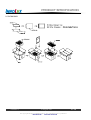
9. PACKAGING
Version 2.4
23 August 2011
The copyright belongs to CHIMEI InnoLux. Any unauthorized use is prohibited.
Data Modul AG - www.data-modul.com
23 / 28
PRODUCT SPECIFICATION
Sea / Land Transportation (40ft Container)
Version 2.4
Air Transportation
23 August 2011
The copyright belongs to CHIMEI InnoLux. Any unauthorized use is prohibited.
Data Modul AG - www.data-modul.com
24 / 28
PRODUCT SPECIFICATION
10. DEFINITION OF LABELS
10.1 CMO MODULE LABEL
The barcode nameplate is pasted on each module as illustration, and its definitions are as following explanation.
CHI
E207943
MEI
G070Y2 -L01
OPTOELECTRONICS
Rev.XX
MADE IN TAIWAN
RoHS
XXXXXXXYMDLNNNN
(a) Model Name: G070Y2 -L01
(b) Revision: Rev. XX, for example: A1, …, C1, C2 …etc.
(c) Serial ID: X X X X X X X Y M D X N N N N
Serial No.
CMO Internal Use
Year, Month, Date
CMO Internal Use
Revision
CMO Internal Use
Serial ID includes the information as below:
(a) Manufactured Date: Year: 1~9, for 2001~2009
Month: 1~9, A~C, for Jan. ~ Dec.
Day: 1~9, A~Y, for 1st to 31st, exclude I , O and U
(b) Revision Code: cover all the change
Serial No.: Manufacturing sequence of product
Version 2.4
23 August 2011
The copyright belongs to CHIMEI InnoLux. Any unauthorized use is prohibited.
Data Modul AG - www.data-modul.com
25 / 28
PRODUCT SPECIFICATION
11. PRECAUTIONS
11.1 ASSEMBLY AND HANDLING PRECAUTIONS
(1) Do not apply rough force such as bending or twisting to the module during assembly.
(2) To assemble or install module into user’s system can be only in clean working areas. The dust and oil
may cause electrical short or worsen the polarizer.
(3) It’s not permitted to have pressure or impulse on the module because the LCD panel and Backlight will
be damaged.
(4) Always follow the correct power sequence when LCD module is connecting and operating. This can
prevent damage to the CMOS LSI chips during latch-up.
(5) Do not pull the I/F connector in or out while the module is operating.
(6) Do not disassemble the module.
(7) Use a soft dry cloth without chemicals for cleaning, because the surface of polarizer is very soft and
easily scratched.
(8) It is dangerous that moisture come into or contacted the LCD module, because moisture may damage
LCD module when it is operating.
(9) High temperature or humidity may reduce the performance of module. Please store LCD module within
the specified storage conditions.
(10) When ambient temperature is lower than 10ºC may reduce the display quality. For example, the
response time will become slowly, and the starting voltage of CCFL will be higher than room
temperature.
(11) Do not keep same pattern in a long period of time. It may cause image sticking on LCD
11.2 SAFETY PRECAUTIONS
(1) Do not disassemble the module or insert anything into the Backlight unit to prevent electrical shock.
(2) If the liquid crystal material leaks from the panel, it should be kept away from the eyes or mouth. In
case of contact with hands, skin or clothes, it has to be washed away thoroughly with soap.
(3) After the module’s end of life, it is not harmful in case of normal operation and storage.
Version 2.4
23 August 2011
The copyright belongs to CHIMEI InnoLux. Any unauthorized use is prohibited.
Data Modul AG - www.data-modul.com
26 / 28
Data Modul AG - www.data-modul.com
Data Modul AG - www.data-modul.com
Specification
AST/ATP Series
Revision 11
Version March 23, 2010
Data Modul AG - www.data-modul.com
Table of Contents
1. Product Specifications ...........................................................................................................................3
1-1. Product Applicable .............................................................................................................................3
1-2. Structure.............................................................................................................................................3
1-3. Environmental Specifications .............................................................................................................3
1-4. Mechanical Characteristics ................................................................................................................3
1-5. Electrical Characteristics ....................................................................................................................3
1-6. Appearance ........................................................................................................................................4
2. Testing Regulation ..................................................................................................................................5
2-1. Testing Regulation..............................................................................................................................5
2-2. Environmental Specifications .............................................................................................................5
2-3. Mechanical Characteristics ................................................................................................................5
2-4. Electrical Characteristics ....................................................................................................................6
2-5. Appearance ........................................................................................................................................6
3. Reliability Condition ...............................................................................................................................7
3-1. Temperature Condition .......................................................................................................................7
4. Recommended Connector .....................................................................................................................7
4-1. Recommended Connector .................................................................................................................7
5. Handling Notes........................................................................................................................................8
5-1. Precautions ........................................................................................................................................8
5-2. Handling Notes...................................................................................................................................8
5-3. Construction Notes.............................................................................................................................8
5-4. Electrical & Software Notice ...............................................................................................................8
5-5. Mounting Notes ..................................................................................................................................9
6. Warranty ................................................................................................................................................10
6-1. Warranty Period ...............................................................................................................................10
6-2. Warranty Target................................................................................................................................10
6-3. Warranty Exceptions ........................................................................................................................10
6-4. Tools.................................................................................................................................................10
6-5. Changes...........................................................................................................................................10
7. Revision history .................................................................................................................................... 11
2
Rev. 11©1999 - 2010 DMC Co., Ltd.
Data Modul AG - www.data-modul.com
2
1. Product Specifications
1-1. Product Applicable
§ This specification is applied to the analog resistive touchscreen: ATP/AST Series.
1-2. Structure
§ Dimensions, structure, and shape are referred on the drawing attached.
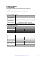
1-3. Environmental Specifications
Specification
Value
Operating Temperature
-20°C to 70°C (no condensation)
Operating Humidity
-20°C to 60°C Less than 90%RH (no condensation)
3
Exceeding 60°C 133.8g/m (no condensation)
Storage Temperature
-40°C to 80°C (no condensation)
Storage Humidity
-40°C to 60°C Less than 95%RH (no condensation)
Exceeding 60°C 142.9g/m3 (no condensation)
Chemical Resistance
(top surface)
Toluene, Tricholoroethylene, Athetone, Alcohol,
Gasoline, Machine Oil, Ammonia, Glass Cleaner,
Mayonnaise, Ketchup, Wine, Salad Oil, Vinegar, Lipstick, etc.
1-4. Mechanical Characteristics
Specification
Value
Activation Force
0.05N to 0.8N
Operating Life
Input (finger)
10,000,000 hits
Character Input (pen)
100,000 characters
Light Transmittance
Over 80% (typical value at full wavelength)
Surface Hardness
Over 2H (by JIS pencil hardness)
1-5. Electrical Characteristics
Specification
Value
Maximum Voltage
Maximum Current
Linearity
Terminal Resistance
Insulation Resistance
Chattering
DC6V
Top Electrode
100mA
Bottom Electrode
100mA
Between the Top and Bottom
0.5mA
Under ±2% (Under ±1% (typical value))
Top Electrode
Less than 1kΩ
Bottom Electrode
Less than 1kΩ
Neighboring Terminals
Over 20MΩ at 25V
Active Area Electrodes
Over 20MΩ at 25V
Less than 10msec at ON/OFF.
3
Rev. 11©1999 - 2010 DMC Co., Ltd.
Data Modul AG - www.data-modul.com
3
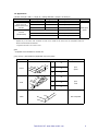
1-6. Appearance
§ Scratch, dust (W = width, L = length, D = average diameter = (longest + shortest) /2)
Item
Width (mm)
Length (mm)
Acceptable Numbers
Linear(Scratch/Dust)
Over 0.1mm in
diameter refer to the
Circular.
0.1≥W>0.05
4≥L
1pcs in φ30mm
0.05≥W>0.03
10≥L
2pcs in φ20mm
0.03≥W
20≥L
Acceptable
Circular
(Scratch/Dust)
0.4≥D>0.3 *1
1pcs in viewing area *1
0.3≥D>0.2
2pcs in φ30mm
0.2≥D
Acceptable
Total
Within 5pcs
/panel
Applied only in the Active Area. Scratches or dusts in the outside of the Active Area are acceptable unless the
electrical characteristics are affected.
*1 Applied to the size of 14 inches or more.
§ Dirt
Acceptable if not noticeable on a black mat.
§ Tip, crack (t = glass thickness) (applicable only for the glass)
Item
Size (mm)
Z
Corner
X
Y
X
Y
Side
Z
Acceptable Numbers
X
≤3
Y
≤3
Z
≤t
X
≤5
Y
≤3
Z
≤t
Crack
2pcs
/panel
2pcs
/side
Not acceptable
4
Rev. 11©1999 - 2010 DMC Co., Ltd.
Data Modul AG - www.data-modul.com
4
2. Testing Regulation
2-1. Testing Regulation
§ If the regulation is not specified, the test is performed under the supplier’s regulation.
§ Tests are performed under the room temperature unless specified. The room temperature is referred as
follows:
Temperature: 20°C±5°C
Humidity:
65%±10%RH
2-2. Environmental Specifications
§ Chemical Resistance Test
Condition:
Tested after leaving the chemical on the surface for 12 hours being wiped off by cloth.
Judgement:
Must be no effect in appearance.
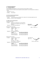
2-3. Mechanical Characteristics
§ Activation Force Test
Condition:
Judgement:
Measured by depressing the point between
the dots to the conduction by the testing rod
(Figure 1).
Must satisfy the specification.
Silicon Rubber
(Hardness: 60°)
Tip: R = 4.0
§ Operating Life Test (Finger)
Condition:
Testing rod: Refer to Figure 1
Voltage:
DC5V
Load:
3N
Cycle:
2 hits/sec
Judgement:
Must satisfy the following:
Activation Force:
Linearity:
Terminal Resistance:
Insulation Resistance:
Figure 1. Testing rod 1
Must satisfy the specification.
Must satisfy the specification.
Must satisfy the specification.
Must satisfy the specification.
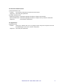
§ Operating Life Test (Pen)
Condition:
Testing rod: Refer to Figure 2
Voltage:
DC5V
Load:
2.5N
Input size: 10 x 10 mm
Input character: A to Z/minute
Judgement:
Must satisfy the following:
Activation Force:
Linearity:
Terminal Resistance:
Insulation Resistance:
Polyacetal resin
Tip: R = 0.8
Figure 2. Testing rod 2
Must satisfy the specification.
Must satisfy the specification.
Must satisfy the specification.
Must satisfy the specification.
5
Rev. 11©1999 - 2010 DMC Co., Ltd.
Data Modul AG - www.data-modul.com
5
2-4. Electrical Characteristics
§ Terminal Resistance Test
Condition:
Top and bottom electrodes are measured at the terminal.
Judgement:
Must satisfy the specification.
§ Insulation Resistance Test
Neighboring Terminals: Measured by applying the reference voltage to the terminals
Active Area Electrodes: Measured by applying the reference voltage to the top and bottom electrodes.
Judgement:
Must satisfy the specification.
2-5. Appearance
§ Appearance Test
Condition:
Tested by an examiner with over 1.0 eyesight at 30cm away from the product under the
transmittable light at over 60° the surface of the product.
Judgement:
Must satisfy the specification.
Data Modul AG - www.data-modul.com
6
3. Reliability Condition
3-1. Temperature Condition
§ Temperature Condition Test
Following test are performed in the condition with no dew condensation:
Cold Test:
Tested after leaving the parts in -40°C±3°C for 240 hours and in the room temperature
for 2 hours.
Heat Test:
Tested after leaving the parts in 80°C±3°C for 240 hours and in the room temperature for
2 hours.
Humidity Test: Tested after leaving the parts in the temperature 60°C±3°C, humidity 90 to 95% for 240
hours and in the room temperature for 2 hours.
Cycle Test:
Tested after 5 cycles of leaving the parts in the temperature -30°C±3°C for 1 hour and in
the room temperature for 0.5 hours, then leaving the parts in the temperature 70°C±3°C
for 1 hour and in the room temperature for 0.5 hours.
Judgement:
Must satisfy the following:
Activation Force:
Must satisfy the specification.
Linearity:
Must satisfy the specification.
Terminal Resistance:
Must satisfy the specification.
Insulation Resistance: Must satisfy the specification.
Appearance:
Must satisfy the specification.
4. Recommended Connector
4-1. Recommended Connector
Part No.
Pins
Pitch
KCA-K4R
4 pin Double-sided
1.25mm
7
Rev. 11©1999 - 2010 DMC Co., Ltd.
Data Modul AG - www.data-modul.com
7
5. Handling Notes
5-1. Precautions
§ This product is intended for use in standard applications (computers, office automation, and other office
equipment, industrial, communications, and measurement equipment, personal and household devices,
etc.) Please avoid using this product for special applications where failure or abnormal operation may
directly affect human lives, or cause physical injury or property damage, or where extremely high levels
of reliability are required (such as aerospace systems, vehicle operating control, atomic energy controls,
medical devices for life support, etc.).
5-2. Handling Notes
§ Do not depress or scratch the product with any object with a sharp edge or end.
§ Do not forcibly bend or fold the product.
§ When the product is stored, make sure it is packed in a packing box and stored in a storage temperature
range, eliminating any outside load.
§ Do not use or store the product under a condition where the product will be exposed to water, organic
solution or acid.
§ Do not use the product under the direct sunlight.
§ Do not disassemble the product.
§ When you handle the product, Hold the product by its body. Do not hold by the tail.
§ Clean the product with a soft cloth or a soft cloth with neutral detergent or alcohol. When contaminated
by chemicals, wipe them off immediately with caution not to cause injury to human body.
§ The edge of the glass is not rounded and may cause injury.
5-3. Construction Notes
§ The environmental specifications, mechanical characteristics, and electrical characteristics are only
applied to the Active Area.
§ Do not use the touchscreen when the condensation occurs. The condensation inside of the touchscreen
is a natural phenomenon and should disappear after the touchscreen is warmed up.
5-4. Electrical & Software Notice
The best performance can be obtained when used with the original analog resistive touchscreen controller,
“TSC-10” Series. If the touchscreen controller or controller software is to be developed by the customer,
please note the following:
§ There is a contact resistance between the top and bottom electrodes and it changes by the pressure of a
finger or a pen. The data must be read after the contact resistance becomes stabilized.
§ The terminal resistance of the analog resistive touchscreen varies by the individual, time, and
environment. The controller software must have the calibration function to adjust the input position and
the display position.
§ The analog resistive touchscreen outputs 2 point input as 1 point in between the 2 points. The controller
software must not be designed to have the 2 point input function.
§ For drawing applications, the line may be intermittent when the pen comes on the dot spacers. A
software compensation is needed.
8
Rev. 11©1999 - 2010 DMC Co., Ltd.
Data Modul AG - www.data-modul.com
8
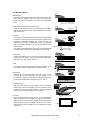
5-5. Mounting Notes
Bezel
Bezel edge must be positioned in the area between the Active
Area and the Viewing Area. The bezel may press the
touchscreen and cause input if the edge enters the Active
Area.
§ Gap between the Bezel and Touchscreen
Active Area
Viewing Area
Bezel
Top Electrode
A gap of approximately 0.5mm is needed between the bezel
and the top electrode. It may cause unexpected input if the
gap is too narrow.
0.5mm
§ Bezel Edge
§ Cushion
If a cushion is used between the bezel and the top electrode,
the cushion must be free enough to absorb the expansion and
contraction difference between the bezel and the top
electrode. If the cushion is squashed too hard, the expansion
and the contraction difference may cause the distortion to the
top electrode.
The cushion must be positioned more than 1mm outward from
an inside of the insulation area. (Please refer to right figure)
Bezel
Cushion
Top Electrode
Insulation Area
Minimum 1mm
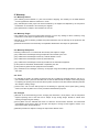
§ Tolerance
There is a tolerance of 0.2 to 0.3mm for the dimensions of the
touchscreen and the tail. A gap must be made to absorb the
tolerance in the case and the connector.
0.2 - 0.3mm
Case
§ Tail
The tail must not be forcibly stressed or bent too hard to avoid
the conduction in the insulated area and wire breaking.
Tail
§ Mounting
Bezel
Touchscreen must be held from the bottom such as the
structure gluing the touchscreen onto the display. If the
touchscreen is glued to the bezel, the adhesion between the
top and bottom electrode is stressed and may come off.
Display
§ Forbidden Area
The area within 2mm from the insulation area is structurally
week for the pressure, espcially for pen use. The film may be
forcibly bent and may cause defection. This area must be
protected by the bezel and input must be avoided.
§ Air Vent
Bezel
Forbidden Area
Most of the touchscreens have the air vent to equalize the
inside air pressure to the outside one. The air vent must be
open and liquid contact must be avoided as the liquid may be
absorbed if the lquid is accumilated near the air vent. The top
electlode must not be swelled by the air pressure from inside
of the case.
Data Modul AG - www.data-modul.com
9
6. Warranty
6-1. Warranty Period
§ The warranty period is limited to 1 year from the date of shipping. The warranty for the initial defection
such as appearance defection is limited to 1 month.
§ Any defected parts under proper use will be examined by the supplier and replaced by the new parts if
the defection is considered to be caused by the supplier.
§ The replacement is subject to be included in the next lot.
6-2. Warranty Target
§ The warranty only covers the product itself and does not cover any damage to others caused by using
this product. Onsite repair or replacement is not supported.
§ We will do our best for delivery problem and product defections, but the warranty for the production line
is not covered.
§ Resistive touchscreens are structurally not repairable. All defections are subject to replacement.
6-3. Warranty Exceptions
Following conditions are not covered with the warranty and subject to charge.
§ Any malfunctions and damages during transportation and transfer by the user.
§ Any malfunctions and damages caused by a natural disaster or a fire.
§ Any malfunctions and damages caused by static electricity
§ Any malfunctions and damages caused by the failure of the associated equipment.
§ If the product is remodeled, disassembled or repaired by the user.
§ If the product is glued onto the equipment and uninstalled.
§ Any malfunctions and damages caused by an improper usage and handling against the specifications
and notes.
6-4. Tools
§ To maintain the quality, the printing screens and the die-cut plates are generally limited to use up to 1
year. Reorders after 1 year from the initial order or from the last renewal are subject to the tooling charge
for replacing the printing screens and the die-cut plates. Reorders for the discontinued standard parts are
also subject to tooling charge.
§ All the tools, such as CAD data (except for the drawing for approval), block copies (films), printing
screens, and die-cut plates are not to be provided for administrative purpose.
6-5. Changes
§ Because of the manufacturing process, changing the dimensions, circuit pattern, and the tail position
requires replacing most of the tools and is subject to high tooling charge. Please be careful when
ordering and approving the drawing.
§ Circuit pattern and the materials that does not affect the environmental, electrical, and mechanical
characteristics such as film, glass, ink and glue are subject to change for the supplier’s reason or for
improvement within the specifications.
§ Standard products are subject to change for improvement without notice.
10
Rev. 11©1999 - 2010 DMC Co., Ltd.
Data Modul AG - www.data-modul.com
10
7. Revision history
Rev1 (April 15, 1998)
Initial release
Rev2 (June 1, 1999)
The overall revision by specification review.
Rev3 (April 1, 2002)
The address in the office was changed by the move.
Rev4 (August 16, 2002)
1-4.Activation Force is changed “50g± 30g” to “0.5N±0.3”.
1-4.Light Transmission is changed 76% to 80%(TYP).
Rev5 (September 3, 2002)
1-3.Operating Temperature is changed “0°C to 60°C” to “-20°C to 70°C”.
1-3.Storing Temperature is changed “-20°C to 70°C” to “-40°C to 80°C”
1-4.Operating Life is changed “1,000,000 hits” to “10,000,000 hits”.
1-5.Linearity is changed “Under ±2%” to “Under ±1% (typical value)”.
Rev6 (June 28, 2004)
1-3.Operating Humidity is changed “Less than 90%RH (no condensation)” to “-20°C to 60°C Less than
3
90%RH (no condensation) Exceeding 60°C 133.8g/m (no condensation)”.
1-3.Storing Humidity is changed “Less than 95%RH (no condensation)” to “-40°C to 60°C Less than
95%RH (no condensation), Exceeding 60°C 142.9g/m3 (no condensation)”.
1-5.Maximum Voltage is changed “DC5V” to “DC6V”.
1-5.Linearity is changed “Under ±1% (typical value)” to “Under ±2% (Under ±1% (typical value))”.
Rev7 (October 15, 2004)
4-4.Electrical & Software Notice: Changed “FIT-10 series” to “TSC-10 series”.
Rev8 (April 7, 2005)
Added Item4 Recommended Connector.
Rev9 (September 6, 2005)
2-3.Mechanical Characteristics: Added Operating Life Test (Pen).
11
Rev. 11©1999 - 2010 DMC Co., Ltd.
Data Modul AG - www.data-modul.com
11
Rev10 (November 10, 2006)
The specification item name was changed.
1-3.”Storing Temperature” to “Storage Temperature”
1-3.”Storing Humidity” to “Storage Humidity”
1-4.”Operating Load” to “Activation Force”
1-4.”Light Transmissivity” to “Light Transmittance”
1-4.”Top Surface Hardness” to “Surface Hardness”
2-3.”Operating Load Test” to “Activation Force Test”
2-3.”Operating Load” to “Activation Force”
3-1.”Operationg Load” to “Activation Force”
1-4.Operating Force is changed “0.5N±0.3N” to “0.05N to 0.8N”.
1-5.Insulation Resistance is changed “Over 100MΩ at 25V” to “Over 20MΩ at 25V”.
1-6.Tip, crack: Deleted “Applied only in the Active Area. Scratches or dusts in the outside of the Active
Area are acceptable unless the electrical characteristics are affected.”.
2-3. § Operating Life Test (Pen) Load: 300g to 250g
5-5. § Cushion: Added an installation position of a cushion.
7.Added Revision History.
Rev11 (March 23, 2010)
1-6. Appearance specification was revised. Characters of scratch/dust were classified into Circular and
Linear. The total acceptable number of scratch/dust was added.
2-3. Unit of Load (g) changed to (N) to unify the unit
2-3. Operating Life Test (Finger) Activation Force, Within ±50% of the specification → Must satisfy
the specification. (Clerical error was corrected)
2-3. Operating Life Test (Pen) Activation Force, Within ±50% of the specification → Must satisfy the
specification. (Clerical error was corrected)
3-1. Temperature Condition
Cold Test -30℃→ -40℃ (Clerical error was corrected)
3-1. Activation Force, Within ±50% of the specification. → Must satisfy the specification
(Clerical error was corrected)
12
Rev. 11©1999 - 2010 DMC Co., Ltd.
Data Modul AG - www.data-modul.com
12
Headquarters:
DATA MODUL AG
Landsberger Str. 322
DE-80687 Munich - Germany
Phone: +49-89-56017-0
Fax: +49-89-56017-119
www.data-modul.com
Logistics, Production & Services:
DATA MODUL Weikersheim GmbH
Lindenstrasse 8
DE-97990 Weikersheim - Germany
Phone: +49-7934-101-0
Fax: +49-7934-101-101
Subsidiaries & Sales Offices:
Germany – Hamburg
Germany – Duesseldorf
Denmark
Dubai
Finland/Baltic
France
Italy
Singapore
Spain
Switzerland
UK
USA
DATA MODUL’s worldwide offices
can be found on our website:
www.data-modul.com/eu/sm/
contact-us/offices.html
DATA MODUL | www.data-modul.com