1
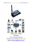
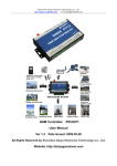
1 CWT5010 User’s manual CONTENTS V3.0 1 PREFACE............................................................................................................................................ 3 2 INTRODUCTION................................................................................................................................. 4 2.1 3 4 PARAMETER................................................................................................................................... 4 INSTALL.............................................................................................................................................. 5 3.1 SIZE ............................................................................................................................................... 5 3.2 LED INDICATOR DESCRIPTION ........................................................................................................ 5 3.3 TERMINAL DESCRIPTION................................................................................................................. 6 SETUP PARAMETERS FOR RTU ..................................................................................................... 7 4.1 ACCESS SETUP MODE .................................................................................................................... 7 4.2 SETUP BASIC PARAMETERS ............................................................................................................ 8 4.2.1 Setup “CS number” .................................................................................................................. 8 4.2.2 Setup basic parameters ........................................................................................................... 8 4.2.3 Alarm parameters..................................................................................................................... 9 4.2.4 ALL SMS .................................................................................................................................11 4.2.5 System Prio .............................................................................................................................11 4.3 INPUT AND OUTPUT ...................................................................................................................... 13 4.3.1 Setup input and output types ................................................................................................. 13 4.3.2 Define alarm and recover sms of digital input........................................................................ 15 4.3.3 Setup inputs timeouts............................................................................................................. 15 4.3.4 Setup digital inputs/outputs port name................................................................................... 16 4.3.5 CS’s DIN authority.................................................................................................................. 17 4.4 SETUP I-SENSORS........................................................................................................................ 18 4.4.1 Buzzer .................................................................................................................................... 18 4.4.2 Tmp100 sensor (optional) ...................................................................................................... 18 4.4.3 Internal battery (optional) ....................................................................................................... 19 4.5 SETUP EXTEND TEMPERATURE SENSOR ........................................................................................ 20 4.5.1 Setup extend temperature...................................................................................................... 20 4.6 OTHERS SETTING......................................................................................................................... 21 4.6.1 Realtime Interlock................................................................................................................... 21 4.6.2 Timers..................................................................................................................................... 22 4.6.3 Weekly timers ......................................................................................................................... 23 4.6.4 Define users commands ........................................................................................................ 23 SHEN ZHEN YIKEHUDONG TECHNOLOGY TRADE LTD TEL:+86-755-26719954 www.mobq2000.com 2 3 CWT5010 User’s manual 1 PREFACE 2 INTRODUCTION Thank you for using the CWT5010 GSM RTU. You will know well about the functions and operation methods of this product quickly through this User’s Manual. This product is mainly used for remote alarming and control application based on GSM network. Please use it according to the parameters and technical specifications in the User’s Manual. Meanwhile, the Notes shall be considered for the usage of radio-control products, especially GSM products. Our Company bears no liability for property loss or bodily injury arising from abnormal or incorrect usage of CWT5010 GSM RTU is designed as a cost effective remote control system alert device. It monitors up to 4 dry contacts and 4 drivable relay outputs. User-defined SMS is sent to pre-configure mobile phone numbers when a pre-defined alarm condition happens. These pre-configured mobile phone numbers can belong to technicians or engineers who are responsible in handling corresponding alarms. With the aid of this GSM RTU, the alarm condition brings attention to in-charge personnel immediately. this product. Besides it allows those mobile phone users to trigger any relay output by using SMS. The output can be connected with alarm indication device, such as alarm, and others. Package list There is a built-in microprocessor chip running on a real-time operating system. It gives immediate response to any change in both inputs and outputs condition. A GSM modem is embedded in the GSM product quantity CWT5010 GSM RTU 1pcs RS232 cable 1pcs 12V Adaptor 1pcs GSM antenna 1pcs CD 1pcs SHEN ZHEN YIKEHUDONG TECHNOLOGY TRADE LTD TEL:+86-755-26719954 RTU, user has to subscribe a SIM card for the GSM RTU. The GSM RTU can be installed in any location under GSM coverage. 2.1 Parameter Parameter item Reference scope DC Power supply 12-24V DC (Standard adapter: DC 12V/1.5A) Power consumption 12V input Max. 150mA/Average 50mA Frequency range Quad-frequency 900/1800/850/1900HMz SIM Card Supporting 3V SIM Card Antenna 50 Ω SMA Antenna interface Serial RS232 Temperature range -30°C ~ +70 °C Humidity range Relative humidity 95% Digital Input 4 digital inputs(Dry contact) output 4 drivable relay outputs(open-collector outputs) Output drive voltage Equal to input DC voltage Output drive power Drive voltage ≤35V, drive current ≤500mA Exterior dimension 95×63×25mm Weight 256 g www.mobq2000.com 4 5 CWT5010 User’s manual 3.3 Terminal Description 3 INSTALL 4 3 2 1 3.1 size ①. DC9-28V (power in) DC positive terminal of the DC power supply (+) GND Negative terminal of the DC power supply (- ) Warning :must be careful that the polarity is not reversed, otherwise, the output will be damaged ②. RS232 3.2 LED indicator description RXD Receive Data Connect RS232 cable orange wire TXD Transmit Data Connect RS232 cable blue wire GND Ground Connect RS232 cable black wire ③. 4 drivable relay output Status Indication description DO0~DO3 negative pole of relay coil Normally light Indicator for power supply, which will be light on when the system DC Positive pole of relay coil on is power on Flicker SMS module signal indicator, which will flicker slowly after the system is registered in GSM network Light on during It will be light on when the system sends sms and light off when handling the handling is over ACT (Orange) Flicker It will flicker periodically when the system is under operation, and the interval time is 6 sec Side led (green) Light on or off Light on during the internal battery is charge up Indicator PWR (Red) NET (Green) SRV (Yellow) SHEN ZHEN YIKEHUDONG TECHNOLOGY TRADE LTD TEL:+86-755-26719954 ④. 4 digital inputs (NO or NC) DI0~DI3 Connect NO or NC GND Connect COM www.mobq2000.com 6 7 CWT5010 User’s manual 4 SETUP PARAMETERS FOR RTU 4.1 Access setup mode 4.2 4.2.1 Setup basic parameters Setup “CS number” RTU under working mode, the “CS number” can send sms commands to control RTU and receive sms Connect RTU and computer with RS232 cable, and open the configuration software, make RTU access setup mode according to the following figure. (include alarm sms, report sms etc). User can set 10 CS numbers, CS0-CS9 Note: Please choose the serial port No. and rate correctly, the default communication rate is 9600; default password is “000000” 4.2.2 Setup basic parameters Definition: Working mode and setup mode In setup mode, all functions are disabled, only to setup parameters. And RTU must be restart to enter working mode, all functions is enabled, the RTU can alarm and be control. NOTE Access setup mode, the simcard and antenna is no need, but access wording mode, the simcard and antenna is necessary. How to know current mode: Method 1: Check the ACT light, if the ACT light flickers twice per second, that means it is under the setup mode; the flicker period of the ACT light can be up to 6 sec under the working mode. Attention: gsm band, com bps, uart, pin code, country code please using the default parameter Method 2: Check the information from the serial port, if the character string of “dtu come in setup mode” occurs, it means that RTU is under the setup mode. SHEN ZHEN YIKEHUDONG TECHNOLOGY TRADE LTD TEL:+86-755-26719954 Alarm for GSM signal low GSM signal normal range is 18-32,RTU sends alarm sms to CS number when RTU’s GSM signal value www.mobq2000.com 8 9 CWT5010 User’s manual below the preset threshold, the default is 11. Daily report enable the option, RTU will send a report sms to CS number at 10:00 every morning for reporting current states, through which the user can make sure the normal operation of RTU. Proof time Proof time is keeping the RTU’s os (operation system) has correct time. RTU can execute daily report, timing arm or disarm, timing output at correct time. Send proof time sms to cs when power up When RTU power up, it send a sms to CS0 to request proof time, CS0 can reply sms”999” to RTU to complete proof time. Send proof time sms to sp when power up SP phone number is a phone that cans automatic reply a SMS to any incoming SMS, RTU use it to update interior Clocker by the timestamp in SMS, the SMS contents is not important. Device description You can add description with RTU (such as install position, user information), the description is show in RTU alarm sms. Device ID The device ID is an 8-byte ASCII characters which is show in RTU state sms. 4.2.3 auto answer call of service phone numbers Attention: This option is valid for the RTU models that have audio interface. If MIC and speaker are connected; RTU auto answer when CS numbers call it, so user can remote monitor voice and speaking. Auto add basic description with alert sms Enable this option, the description (such as install position, user information) that have been defined by user will show in alarm sms and daily report sms. print RTU alarm events by com port Enable this option, when RTU alarm, it sends the alarm data to com port with CWT_IO data format. delay send sms time when alarm(disarm delay) Define the time; you have an enough time to disarm RTU when you go into the monitor area. Holding time after arm(arm delay time) Define the time; you have an enough time to arm RTU when you leave the monitor area. Extend information with report RTU can send report sms to cs phones by timer or user’s inquiry by sms command, this function is designed to let user know the RTU is stilling working and its status, enable or disable follow information to show in report. Alarm parameters Interior temperature: The internal temperature sensor is optional, if RTU has added it, the temperature value will show in the daily report. Attention:A standard RTU have not internal temperature sensor Device Id: enable this option, ID will show in the daily report. Arm status: enable this option, arm or disarm status will show in the daily report. Signal of gsm network: enable this option, GSM signal value will show in the daily report. Device’s memo: enable this option, Device description will show in the daily report. Power supply status: enable this option, the daily report will show power supply status Ex-temperature: Attention: This option is valid for the RTU models that have temperature inputs (DS18B20 inputs). Enable this option, all the value of extend temperature sensor will show in the daily report. Alarm inputs: enable this option, the inputs that are in alarm status will show in the daily report. ring when alert Enable this option, RTU will give CS number a phone call then send sms when alarm SHEN ZHEN YIKEHUDONG TECHNOLOGY TRADE LTD TEL:+86-755-26719954 AD0~AD3: enable those options, all the value of AD input will show in the daily report. www.mobq2000.com 10 11 CWT5010 User’s manual 4.2.4 ALL SMS In this page, you can see all sms contents that you have defined, include digital inputs alarm/recover sms, AD inputs alarm/recover sms etc. you can Double-click it to modify. 4.2.5 Authority Explanation admin Can Arm/disarm or not Modify by sms This CS number can be modify by sms command or not Change cs phones This CS number can modify other CS number by sms command or not Powerup sms Can receive the status sms or not when RTU is restarted by sms command Daily report sms Can receive the daily report or not Timer mms Null Alarm mms Null I-tmp alarm sms Can receive the alarm sms or not when internal temperature sensor alarm I-tmp alarm ring Can receive the alarm phone call or not when internal temperature sensor alarm Power fail sms Can receive the alarm sms of power failure or not Power fail ring Can receive the alarm phone call of power failure or not Signal low alarm Null Sample sms Null M2M svr RTU send sms to the CS number with CWT_IO protocol Arm notify Can receive sms when RTU arm or disarm System Prio In this page, you can set authorization for CS numbers “O” means enable authorization; “X” means disable authorization. SHEN ZHEN YIKEHUDONG TECHNOLOGY TRADE LTD TEL:+86-755-26719954 www.mobq2000.com 12 13 CWT5010 User’s manual 4.3 Input and Output 4.3.1 Setup input and output types Sound Means this channel input alarm event can cause internal buzzer and extend buzzer or siren action. Use digital input 1 as arm control Enable this option, RTU is in arm mode if digital input 1 is opened, RTU is in disarm mode if digital input 1 is closed, so user can connect a button to switch mode for arm or disarm ATTENTION: Use digital input1 as arm control you need select the type of input1 is “TO CLOSE ALARM (LEVEL)” and delete the alarm/recover sms of input 1 Counter Enable or disable this channel input as counter input which catch greater than 100ms plus. Counter upload timer Setup the counter GPRS upload interval Counter upload only changed data Automatic counter upload mode is a mode to Save GPRS, not report data if value not changed. Attention: This option is valid for the RTU models that have GPRS function. Digital inputs types Input signals have two types, EDGE_IN (edge triggering) and LEVEL_IN (state triggering). ATTENTION: The key deference between Level and Edge is Level input has recovery sms message and Level input can repeat alarm status sms notify by an interval. Output types 0 disable 1 relay drivable output Drive relay, drive electricity <0.2A Output drive relay voltage Equal to input DC voltage Output power: Drive voltage ≤35V, drive current ≤200mA Level input alarm 2 Buzzer This line’s actions will synchronize with internal buzzer. 3 SNAPSHOOT This line wills shortly action when any alarm happens. 4 SIREN This line continuous drives for 1 minute by default. And the interval can be user define. Typical edge alarm Remember outputs status RTU’s outputs default status is open; it is possible closed during working. After restart, the outputs will be reset, status is open. If enable the option, output can recover the status that before restart. 24 Hours If enable this option, the digital input will execute alarm action (send alarm sms, interlock etc) when it is triggered, even RTU is in disarm status. SHEN ZHEN YIKEHUDONG TECHNOLOGY TRADE LTD TEL:+86-755-26719954 www.mobq2000.com 14 15 CWT5010 User’s manual 4.3.2 Define alarm and recover sms of digital input 3. Alarms ensure timeouts It is a counter of alarm status ensure timer, designed to avoid shake mistakes. 0 means no counter. All of the input lines sms can be modify. A SMS composed of not more than 60 characters 4.3.3 Setup inputs timeouts 4.3.4 Setup digital inputs/outputs port name This page designed to setup input timeouts property. There are 3 interval related with inputs. 1. Alarm sms limit interval It is designed to avoid amounts of alarm/recover sms in a short time. If you send sms command to require inputs status, there is a contrast of returning from:+8613480165874 High voltage:normal Input 0 :normal Low voltage:alarm Input 1 :alarm High water level:normal Input 2 :normal Low water level:normal Input 3 :normal Have setup input name 2. Alarm sms resend interval It is designed for repeat alarm status notifies to phones, 0 means disable repeat notification. SHEN ZHEN YIKEHUDONG TECHNOLOGY TRADE LTD TEL:+86-755-26719954 from:+8613480165874 Have not setup input name Setup outputs name is same www.mobq2000.com 16 17 CWT5010 User’s manual 4.3.5 CS’s DIN authority 4.4 Setup I-sensors This page can setup the authority of CS phone receive digital input alarm sms and alarm call “O” means this cs phone will receive related line in sms, “X” means not. 4.4.1 Buzzer Attention: This setting is valid for the RTU models that have buzzer. The buzzer can be activated when alarm. In this page, you can enable or disable the buzzer and set interval time of alarm Example: 4.4.2 Tmp100 sensor (optional) Attention: This setting is valid for the RTU models that are added interior temperature sensor, the tmp100 temperature is optional, a standard RTU have not internal temperature sensor. This settings means CS0 don’t receive input 0 alarm CS1 don’t receive input1 alarm sms. CS3 don’t receive input0 alarm sms. SHEN ZHEN YIKEHUDONG TECHNOLOGY TRADE LTD TEL:+86-755-26719954 www.mobq2000.com 18 19 CWT5010 User’s manual You can preset a high and a low temperature value, if temperature is over normal range, RTU alarm. You also can send sms command to RTU to get current temperature. User can set “Adjust” value to calibrating temperature value Timespan of twice alarm sms It is designed to avoid amounts of alarm/recover sms in a short time. TMPRS time: timespan of resend alarm sms It is designed for repeat alarm status notifies to phones, 0 means disable repeat notification. time of ensure alarm It is a counter of alarm status ensure timer, designed to avoid shake mistakes. 0 means no counter. 4.4.3 4.5 4.5.1 Setup extend temperature sensor Setup extend temperature CWT5016 can connect 4 extend wired temperature sensors DS18B20. You can preset a high and a low level for every channel, if the current temperature is above the high level or below the low level, CWT5016 alarm. You can also send sms command to get current temperature. DS18B20 temperature probes temperature range: -55℃~+125℃; precision:±0.5℃ Internal battery (optional) Attention: This setting is valid for the RTU models that are internal battery. It is designed to realize power lost alarm When external power cut off, RTU Powered by internal battery and alarm to cs numbers Adjustments You can set the value to reduce error. time of ensure power alarm When the time of external power lost is over the time, RTU alarm, “0” means disable the function. Battery parameter: Lithium battery Voltage: 3.7V Capacity: 800mAh Limited voltage for charging 4.2V Implementation standard GB/T 18287-2000 Alarm sms interval The time is designed to avoid amounts of alarm/recover sms in a short time. Re-alarm sms interval Designed for repeat alarm status notifies to phones, 0 means disable repeat notification. Alarm ensuring timer It is a counter of alarm status ensure timer, designed to avoid shake mistakes. 0 means no counter. “24 Hours” property If checked, the channel will execute alarm action (send alarm sms, interlock etc) when it is triggered, even CWT5016 is in disarm status. “Sound” property Means this line alarm event will cause internal buzzer and extend buzzer or siren action. “Enable” property Enable or disable this channel’s alarm SHEN ZHEN YIKEHUDONG TECHNOLOGY TRADE LTD TEL:+86-755-26719954 www.mobq2000.com 20 21 CWT5010 User’s manual 4.6 4.6.1 Others setting 4.6.2 Timers Realtime Interlock Timers is designed to time execute task, task include arm, disarm, open/close output etc. Realtime interlock is a local strategy, it is designed to outputs automatically execute action under some internal triggering conditions. Minutes timers 4 minute counters can be set, RTU execute a task every the minute interval. For example, RTU execute output 0 pulse every 30 minutes For example If digital input 0 alert, output 0 close pulse 5 seconds. Second timers 4 second counters can be set, RTU execute a task every the second interval. System timers 6 times can be set in a day, RTU execute a task in each time. For example, at 8:30 execute output 0 on, at 17:00 execute output 0 off. SHEN ZHEN YIKEHUDONG TECHNOLOGY TRADE LTD TEL:+86-755-26719954 www.mobq2000.com 22 23 4.6.3 Weekly timers 7 times can be set in a week, RTU execute a task in each time. For example, execute send daily report at Monday 10:30 RTU 4.6.4 Define users commands Users can define 6 commands instead of system commands. For example, user set “close” instead of system command “IOOH”, so user can send “close” to close output SHEN ZHEN YIKEHUDONG TECHNOLOGY TRADE LTD TEL:+86-755-26719954