1
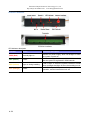
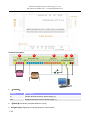
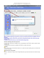
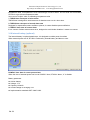
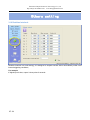
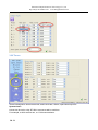
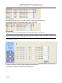
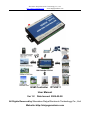
Shenzhen Daiya Electronic Technology Co., Ltd. http://daiya.en.alibaba.com/ www.daiyagsmalarm.com GSM Controller RTU5011 User Manual Ver 1.2 Date Issued: 2009-02-28 All Rights Reserved by Shenzhen Daiya Electronic Technology Co., Ltd. Website: http://daiyagsmalarm.com Shenzhen Daiya Electronic Technology Co., Ltd http://daiya.en.alibaba.com/ www.daiyagsmalarm.com CONTENTS I Preface.....................................................................................................................................3 Package list.......................................................................................................................................................3 II Introduction............................................................................................................................ 4 Features.............................................................................................................................................................4 Parameter..........................................................................................................................................................5 RTU5011 interface........................................................................................................................................... 6 III Configuration guide of RTU5011...................................................................................... 7 3.1 Access setup mode................................................................................................................................ 7 3.2 Add “CS number”.................................................................................................................................... 9 3.3 Basic parameter configuration............................................................................................................10 3.4 Parameters for alarm............................................................................................................................11 3.5 ALL SMS................................................................................................................................................ 12 3.6 CS’s authority........................................................................................................................................ 13 3.7 Inputs_Outputs types........................................................................................................................... 14 3.8 Define alarm and recover sms of digital input................................................................................. 15 3.9 Digital inputs timeouts..........................................................................................................................16 3.10 Config digital inputs/outputs name.................................................................................................... 17 3.11 CS’s DIN authority................................................................................................................................ 18 3.12 Analog input alarm................................................................................................................................19 3.13 Define alarm and recover sms of AD input...................................................................................... 20 3.14 Config AD inputs name........................................................................................................................20 3.15 CS’s AIN Authority................................................................................................................................ 21 3.16 Buzzer.....................................................................................................................................................22 3.17 Tmp100 sensor (optional)................................................................................................................... 22 3.18 Internal battery (optional).................................................................................................................... 23 3.19 Realtime Interlock.................................................................................................................................24 3.20 Timers..................................................................................................................................................... 25 3.21 Weekly Timers.......................................................................................................................................26 3.22 Program Interlock................................................................................................................................. 26 3.23 Define users commands......................................................................................................................27 2 / 31 Shenzhen Daiya Electronic Technology Co., Ltd http://daiya.en.alibaba.com/ www.daiyagsmalarm.com I Preface Thank you for using the RTU5011 GSM RTU. You will know well about the functions and operation methods of this product quickly through this User’s Manual. This product is mainly used for remote alarming and control application based on GSM network. Please use it according to the parameters and technical specifications in the User’s Manual. Meanwhile, the Notes shall be considered for the usage of radio-control products, especially GSM products. Our Company bears no liability for property loss or bodily injury arising from abnormal or incorrect usage of this product. Package list GSM RTU 12V Adaptor 3 / 31 RS232 cable GSM antenna CD Shenzhen Daiya Electronic Technology Co., Ltd http://daiya.en.alibaba.com/ www.daiyagsmalarm.com II Introduction RTU5011 GSM RTU is designed as a cost effective remote control system alert device. It monitors up to 8 dry contacts and 8 drivable relay outputs and 4 AD input. User-defined SMS is sent to pre-configure mobile phone numbers when a pre-defined alarm condition happens.These pre-configured mobile phone numbers can belong to technicians or engineers who are responsible in handling corresponding alarms. With the aid of this GSM RTU, the alarm condition brings attention to in-charge personnel immediately. Besides it allows those mobile phone users to trigger any relay output by using SMS. The output can be connected with alarm indication device, such as alarm, and others. There is a built-in microprocessor chip running on a real-time operating system. It gives immediate response to any change in both inputs and outputs condition. A GSM modem is embedded in the GSM RTU, user has to subscribe a SIM card for the GSM RTU. The GSM RTU can be installed in any location under GSM coverage. Features 8 digital inputs, connect dry contact device 8 relay drivable outputs(12V-24V),drive electricity <0.2A 4 Analog input, 0-53 Ma,10 precision Reliable performance with built-in double watchdog Automatic device condition report through SMS every 24 hour interval User-defined alarm condition (normally close or open), alarm and recovery SMS message for each alarm point; Supporting drive relay output Maximum of 10 mobile phone numbers can be programmable Supporting voice monitoring Inside temperature sensor (optional) Being available for internal battery and providing power cut off alarm (optional) Configuration can be done via COM port. 4 / 31 Shenzhen Daiya Electronic Technology Co., Ltd http://daiya.en.alibaba.com/ www.daiyagsmalarm.com Relay drive output Digital inputs GSM Engine RS-232 Interface Watchdog NXP Industrial MCU Power management Audio management Internal temperature sensor DC Input Parameter Parameter item Reference scope DC Power supply 9-28V DC (Standard adapter: DC 12V/1.5A) Power consumption 12V input Frequency range Dual-frequency 900/1800 or 900/1800/850/1900 SIM Card Supporting 3V SIM Card Antenna 50 Ω SMA Antenna interface Serial RS232 Temperature range -20-+70 °C Humidity range Relative humidity 95% Output drive voltage Equal to input DC voltage Output drive power Drive voltage ≤35V, drive current ≤200mA On state input current Max. 0.33mA Input signal Dry contact Exterior dimension 130×80×25mm Weight 330 g 5 / 31 Max. 50mA/Average 50mA Battery Shenzhen Daiya Electronic Technology Co., Ltd http://daiya.en.alibaba.com/ www.daiyagsmalarm.com RTU5011 interface RTU5011 interface LED indicator description Indicator Status Indication description PWR (Red) Normally light on Indicator for power supply, which will be light on when the system is power on NET (Green) Flicker SMS module signal indicator, which will flicker slowly after the system is registered in GSM network SRV (Yellow) Light on during handling It will be light on when the system receives or sends short messages and light off when the handling is over ACT (Orange) Flicker It will flicker periodically when the system is under operation, and the interval time is 6 sec 6 / 31 Shenzhen Daiya Electronic Technology Co., Ltd http://daiya.en.alibaba.com/ www.daiyagsmalarm.com Terminal Description 5 AD Device 4 3 Relay 1. [DC9-28V] Terminal Description DC positive terminal of the DC power supply (+) GND Negative terminal of the DC power supply (- ) 2. [RS232]:Connecting computer RS232 to config 3. 8 Digital input: Digital input connecting open or close contact 7 / 31 2 1 Shenzhen Daiya Electronic Technology Co., Ltd http://daiya.en.alibaba.com/ www.daiyagsmalarm.com 4. 8 relay drivable output: driving relay close or open, Output drive voltage Equal to input DC voltage Positive pole of relay coil connecting DC, negative pole of relay coil connecting DO, 5. 4 AD input: connecting analog device and receive 0 to 53 mA signal. III Configuration guide of RTU5011 Basic Parameters 3.1 Access setup mode Connect RTU5011 with RS232 of the computer and open the configuration software, make RTU5011 access setup mode according to the following figure. Note: Please choose the serial port No. and rate correctly, the default communication rate is 9600; default password is “000000” 8 / 31 Shenzhen Daiya Electronic Technology Co., Ltd http://daiya.en.alibaba.com/ www.daiyagsmalarm.com Definition: Working mode and setup mode In setup mode, all functions is disabled, only to set parameters. And RTU5011 must be restart to enter working mode. In working mode, all functions is enabled, the RTU5011 can alarm and control. NOTE Access setup mode, the simcard and antenna is no need, but access wording mode, the simcard and antenna is necessary. How to know current mode: Method 1: Check the ACT light, if the ACT light flickers twice per second, that means it is under the setup 9 / 31 Shenzhen Daiya Electronic Technology Co., Ltd http://daiya.en.alibaba.com/ www.daiyagsmalarm.com mode currently; the flicker period of the ACT light can be up to 6 sec under the working mode Method 2: Check the information from the serial port, if the character string of “dtu come in setup mode” occurs, it means that RTU5011 is under the setup mode. 3.2 Add “CS number” RTU5011 under working mode, the “CS number” can send sms commands to control RTU5011 and receive RTU5011 sms (include alarm sms, report sms etc). User can set 10 CS numbers, CS0-CS9 10 / 31 Shenzhen Daiya Electronic Technology Co., Ltd http://daiya.en.alibaba.com/ www.daiyagsmalarm.com 3.3 Basic parameter configuration Attention:gsm band, uart bps, uart, pin code, country code please using the default parameter 1. Alarm for GSM signal low: GSM signal normal range is 18-32,RTU5011 will send alarm sms to user when RTU5011’s GSM signal value below 11 2. Daily report: When the daily report function is used, RTU5011 will send a report sms to all CS numbers at 10:00 every morning for reporting current states, through which the user can make sure the normal operation of RTU5011. 3. Prooftime Prooftime is keeping the RTU5011’s os (operation system) has correct time. RTU5011 can execute daily report, timing arm or disarm, timing output at correct time. Send prooftime sms to cs when powerup: when RTU5011 powerup, it send a sms to CS0 to request prooftime, CS0 can reply sms”999” to RTU5011 to complete prooftime. Send prooftime sms to sp when powerup: sp number is a service number of GSM operator, when RTU5011 powerup, it send a sms to sp, and waiting sp reply a sms to complete prooftime. Attention:if GSM operator has not provide sp number or such services, you need not enable the option 4. Device description: you can add description with RTU5011 (such as install position , user information),the description will show in sms which RTU5011 send to you 5. Device ID: The device ID is a 8-byte ASCII characters which will be showed in the short-message received by CS, for example: 11 / 31 Shenzhen Daiya Electronic Technology Co., Ltd http://daiya.en.alibaba.com/ www.daiyagsmalarm.com 3.4 Parameters for alarm 1. ring when alert Enable this option, RTU5011 will give CS number a phone call then send sms when alarm 2. auto answer call for service phonenumber Enable this option, RTU5011 can auto answer call for service phone number, if MIC and speaker have been connected, user can monitor voice and speaking. 3. Auto add basic description with alert sms Enable this option, the description (such as install position, user information) that have been defined by user will show in sms which RTU5011 send to service phone number. 4. print RTU alarm events by com port Enable this option, when RTU5011 alarm, it send the alarm data to com port in RTU_IO data format 5. Arm delay and disarm delay Define the time of “delay send sms time when alarm” (disarm delay time), in this way, you have an enough time to set RTU5010 in disarm mode when you go into the monitor area. Define the time of “holding time after disarm” (arm delay time), in this way, you have an enough time to set RTU5010 in arm mode when user leave the monitor area. 6. Extend information with report RTU can send report sms to cs phones by timer or user’s inquiry by sms command, this function is designed to let user have chance to know the RTU is stilling working and main status of the RTU. 12 / 31 Shenzhen Daiya Electronic Technology Co., Ltd http://daiya.en.alibaba.com/ www.daiyagsmalarm.com Multi parameters can be selected into daily report, include: a. Interior temperature: if your’s RTU5011 has added internal temperature sensor, the termperature value will show in the daily report. Attention:A standard RTU5011 have not internal temperature sensor b. Device Id: enable this option, ID will show in the daily report. c. Arm status: enable this option, arm or disarm status will show in the daily report. d. Signal of gsm network: enable this option, GSM signal value will show in the daily report. e. Device’s memo info: enable this option, Device description will show in the daily report. f. Power supply status: enable this option, the daily report will show power supply status g. Alarm digital inputs: enable this option, all digital input status (on or off) will show in the daily report. h. AD0~AD3: enable those options, all the value of AD input will show in the daily report. From: +8613480165874 Equipment Id: 00000001 Time: 9:58 Signal value: 27 Power supply: Normal Computer temperature: 30.5 Description: Machine Room A1, Floor 4, Building 3 AD input0: 12 AD input1: 27 AD input2: 32 AD input3: 11 3.5 ALL SMS In this page, you can see all sms contents that you have defined, include digital inputs alarm/recover 13 / 31 Shenzhen Daiya Electronic Technology Co., Ltd http://daiya.en.alibaba.com/ www.daiyagsmalarm.com sms, AD inputs alarm/recover sms etc. you can Double-click it to modify. 3.6 CS’s authority The explanation of the CS’s authority (“O” is enable, “X” is disable) Authority Explanation admin Can Arm/disarm or not Modify by sms This CS number can be modify by sms command or not Modify servers This CS number can modify other CS number by sms command or not Powerup sms Can receive the status sms or not when RTU is restarted by sms command Daily report Can receive the daily report or not Timer mms Null Alarm mms Null I-tmp sms Can receive the alarm sms or not when internal temperature sensor alarm I-tmp ring Can receive the alarm phone call or not when internal temperature sensor alarm Battery fail sms Can receive the alarm sms of power failure or not Battery fail ring Can receive the alarm phone call of power failure or not Signal low alarm Null Sample sms Null M2M svr Null Arm notify Null PC alarm Null 14 / 31 Shenzhen Daiya Electronic Technology Co., Ltd http://daiya.en.alibaba.com/ www.daiyagsmalarm.com Inputs_Outputs 3.7 Inputs_Outputs types Digital inputs types RTU5011 provide 8 digital inputs, input signals can be divided into two types, EDGE_IN (edge triggering) and LEVEL_IN (state triggering). ATTENTION: The key deference between Level and Edge is Level input has recovery notify message and Level inputs can repeat alarm status sms notify by an interval. Level input alarm edge alarm 15Typical / 31 Shenzhen Daiya Electronic Technology Co., Ltd http://daiya.en.alibaba.com/ www.daiyagsmalarm.com “24 Hours” property: If checked, the digital input will execute alarm action (send alarm sms, interlock etc) when it is triggered, even RTU5011 is in disarm status. “Sound” property: Means this line alarm event will cause internal buzzer and extend buzzer or siren action. “Use digital input 1 as arm control” property: Enable this option, RTU5011 is in arm mode if digital input 1 is opened, RTU5011 is in disarm mode if digital input 1 is closed, so user can connect a button to switch mode for arm or disarm ATTENTION: Use digital input1 as arm control you need select the type of input1 is “TO CLOSE ALARM (LEVEL)” and delete the alarm/recover sms of input 1 Output types 0 disable 1 relay drivable output 8 relay drivable outputs,drive electricity <0.2A Output drive relay voltage Equal to input DC voltage Output power: Drive voltage ≤35V, drive current ≤200mA 2 Buzzer This line’s actions will synchronize with internal buzzer. 3 SNAPSHOOT This line wills shortly action when any alarm happens. 4 SIREN This line continuous drives for 1 minute by default. And the interval can be user define. Remember outputs status RTU5011’s outputs default status is open; it is possible closed during working. After restart, the outputs will be reset, status is open. If check the option, output can recover the status that before restart. 16 / 31 Shenzhen Daiya Electronic Technology Co., Ltd http://daiya.en.alibaba.com/ www.daiyagsmalarm.com 3.8 Define alarm and recover sms of digital input All of the input line sms can be modify and re-define. ATTENTION: a SMS composed of not more than 60 characters 3.9 Digital inputs timeouts 17 / 31 Shenzhen Daiya Electronic Technology Co., Ltd http://daiya.en.alibaba.com/ www.daiyagsmalarm.com This page designed to setup input timeouts property. There are 3 interval related with inputs. 1. Alarm sms limit interval designed to avoid amounts of alarm/recover sms in a short time. 2. Alarm sms resend interval designed for repeat alarm status notifies to phones, 0 means disable repeat notification. 3. Alarms ensure timeouts is a counter of alarm status ensure timer, designed to avoid shake mistakes. 0 means no counter. 18 / 31 Shenzhen Daiya Electronic Technology Co., Ltd http://daiya.en.alibaba.com/ www.daiyagsmalarm.com 3.10 Config digital inputs/outputs name If you send sms command to require inputs status, there is a contrast of returning from:+8613480165874 from:+8613480165874 High voltage:normal Input 0 :normal Low voltage:alarm Input 1 :alarm High water level:normal Input 2 :normal Low water level:normal Input 3 :normal Have configed input name Have not configed input name Config outputs name is same 3.11 CS’s DIN authority This page can setup the table of CS phone receive digital input line in alarm property. “O” means this Cs phone will receive related line in sms, “X” means not. 19 / 31 Shenzhen Daiya Electronic Technology Co., Ltd http://daiya.en.alibaba.com/ www.daiyagsmalarm.com Example: This settings means CS0 don’t receive line0 alarm CS1 don’t receive line1 alarm sms. 20 / 31 Shenzhen Daiya Electronic Technology Co., Ltd http://daiya.en.alibaba.com/ www.daiyagsmalarm.com ADC_Params 3.12 Analog input alarm The analog input are designed to receive 0 to 53 mA signal from an analog sensor You can preset a high and a low level for every AD input, if the input electrical signal is above the high level or below the low level, RTU5011 alarm. You can also send sms command to RTU5011 to get current value. Example: RTU5011 connect a temperature transmitter, it analog output range is 4-20 ma for monitor temperature range is 0℃-50℃, you need get alarm and current temperature value when temperature is above 40℃ or below 10℃ Preset the values for “high”, ”low”, ”scale”, ”base” are: “Urgent” property: If checked, in any case, the RTU5011 will execute alarm action (send alarm sms, interlock etc) when the AD input is over normal range, even RTU5011 is in disarm status. “Sound alarm” property: means this line alarm event will cause internal buzzer and extend buzzer or siren action. Upload span: If the variation scope of AD input is more than the value of “upload span”, RTU5011 alarm 1. AINAS time : minimum time of twice AD alarm sms After executed a alarm action (send alarm sms, interlock etc.)When AD inputs over normal range, in the AINAS time RTU5011 will not execute any alarm action (send alarm sms, interlock etc.) even AD inputs are over normal range frequently. The purpose of setting AINAS time is user will not receive many alarm 21 / 31 Shenzhen Daiya Electronic Technology Co., Ltd http://daiya.en.alibaba.com/ www.daiyagsmalarm.com sms in the time during the AD input is over normal range frequently. “0” is disable 2. AINLS time: interval of resend AD alarm state sms After executed a alarm action(send alarm sms, interlock etc.) when AD inputs over normal range, if the duration of the alarm signal overrun the AINLS time,RTU5011 will execute a alarm action(send alarm sms, interlock etc.) again. The purpose of setting AINLS time is alarm to user repeatedly at regular intervals during the AD input is in state of over normal range. “0” is disable 3. AINDLY time: timespan of ensure AD alarm RTU5011 will not execute any alarm action(send alarm sms, interlock etc.) in the AINDLY time even AD inputs is over normal range, if the duration of the alarm signal overrun the AINDLY time,RTU5011 will execute a alarm action(send alarm sms, interlock etc.). “0” is disable 3.13 Define alarm and recover sms of AD input The current value is showed automatically in end of alarm or recovers sms. ATTENTION: a SMS composed of not more than 60 characters 22 / 31 Shenzhen Daiya Electronic Technology Co., Ltd http://daiya.en.alibaba.com/ www.daiyagsmalarm.com 3.14 Config AD inputs name If you send sms command to require AD inputs value, the AD inputs name show in the sms For example, set the AD input 0 channel name is “temperature”, the sms is: From:+8613480165874 Temperature current value :21.33 AD input 1 current value:60 AD input 2 current value:0 AD input 3 current value:0 ATTENTION: a name composed of not more than 24 characters 3.15 CS’s AIN Authority This page can setup the table of CS phone receive AD input line in alarm property. “O” means this Cs phone will receive related line in sms, “X” means not. 23 / 31 Shenzhen Daiya Electronic Technology Co., Ltd http://daiya.en.alibaba.com/ www.daiyagsmalarm.com 24 / 31 Shenzhen Daiya Electronic Technology Co., Ltd http://daiya.en.alibaba.com/ www.daiyagsmalarm.com I-sensors 3.16 Buzzer A buzzer is installed in the RTU5011. The buzzer will be activated when alarm, it can be stopped by the buzzer reset button on RTU5011 panel, or through sending the command with CS number remotely. In this page, you can enable or disable the buzzer and set interval time of alarm 3.17 Tmp100 sensor (optional) TMP100 as an optional temperature sensor can inside RTU5011; you can preset a high and a low 25 / 31 Shenzhen Daiya Electronic Technology Co., Ltd http://daiya.en.alibaba.com/ www.daiyagsmalarm.com temperature value, if temperature is over normal range, RTU5011 alarm. You can send sms command to RTU5011 to get current temperature value. User can set “Adjust” value to calibrating temperature value 1. TMPAS time: timespan of twice alarm TMPAS time is designed to avoid amounts of alarm/recover sms in a short time. 2. TMPRS time: timespan of resend alarm sms Designed for repeat alarm status notifies to phones, 0 means disable repeat notification. 3. TMPDLY time: time of ensure alarm It is a counter of alarm status ensure timer, designed to avoid shake mistakes. 0 means no counter. 3.18 Internal battery (optional) The internal battery is optional attachment; it is designed to realize power lost alarm When external power cut off, RTU5011 Powered by internal battery and alarm to user POWDLY time: time of ensure power alarm When the time of external power lost is over POWDLY time, RTU5011 alarm, “0” is disable Battery parameter: Lithium battery Voltage: 3.7V Capacity: 800mAh Limited voltage for charging 4.2V Implementation standard GB/T 18287-2000 26 / 31 Shenzhen Daiya Electronic Technology Co., Ltd http://daiya.en.alibaba.com/ www.daiyagsmalarm.com Others setting 3.19 Realtime Interlock Realtime interlock is a local strategy, it is designed to outputs execute action automatically under some internal triggering conditions, For example If digital input 0 alert, output 0 close pulse 5 seconds 27 / 31 Shenzhen Daiya Electronic Technology Co., Ltd http://daiya.en.alibaba.com/ www.daiyagsmalarm.com 3.20 Timers Timers is designed to time execute task, task include arm, disarm, open/close output etc. System timers 6 times can be set in a day, RTU5011 execute a task in each time. For example, at 8:30 execute arm, at 17:00 execute disarm. 28 / 31 Shenzhen Daiya Electronic Technology Co., Ltd http://daiya.en.alibaba.com/ www.daiyagsmalarm.com Minutes timers Set minutes value for the timers, RTU5011 execute a task every the interval time. For example, RTU5011 execute output 0 pulse every 30 minutes Second timers Set second value for the timers, RTU5011 execute a task every the interval time. ATTENTION: before you the timers, you have to update RTU5011’s clock, the method of update clock please see “Basic parameter configuration” above 3.21 Weekly Timers 7 times can be set in a week, RTU5011 execute a task in each time. For example, at Monday 10:30 execute send daily report 29 / 31 Shenzhen Daiya Electronic Technology Co., Ltd http://daiya.en.alibaba.com/ www.daiyagsmalarm.com 3.22 Program Interlock Program interlock is a local strategy; it is stronger and more flexible than realtime interlock. You can set RTU5011 execute many actions automatically according to various types of system events. If event happens, RTU5011 execute action. For example, if RTU5011 powerup, output 0 pulse 1 second 3.23 Define users commands Users can define 6 commands instead of system commands. For example, user set “close” instead of system command “IOOH”, so user can send “close” to close output 30 / 31 Shenzhen Daiya Electronic Technology Co., Ltd http://daiya.en.alibaba.com/ www.daiyagsmalarm.com 31 / 31