1
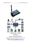
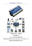
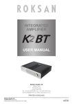
“Automation Gone Cellular” Model CS-440 Software Programming Guide A product of: P.O. Box 33157 Cleveland, Ohio 44212 www.cell-switch.com Cell Switch® Model CS-440 Programmer Software Version 2.54 CONTENTS I Preface ....................................................................................................................... 3 Package componentst...................................................................................................................... 3 II Introduction .............................................................................................................. 4 Features ............................................................................................................................................. 4 Parameter........................................................................................................................................... 5 Dimensions......................................................................................................................................... 7 Terminal Description........................................................................................................................... 8 III Configuration guide of CELL SWITCH® ............................................................... 9 3.1 Access setup mode ................................................................................................................... 9 3.2 Add “CS number” ..................................................................................................................... 10 3.3 Basic parameter configuration ................................................................................................. 11 3.4 Parameters for alarm ............................................................................................................... 13 3.5 ALL SMS .................................................................................................................................. 15 3.6 CS’s authority........................................................................................................................... 15 3.7 Inputs/Outputs types ................................................................................................................ 17 3.8 Define alarm and recover sms of digital inputs ....................................................................... 19 3.9 Digital input timeouts ............................................................................................................... 19 3.10 Config digital inputs/outputs name .......................................................................................... 20 3.11 CS’s DIN authority ................................................................................................................... 21 3.12 CS’s AIN Authority.................................................................................................................... 21 3.13 Buzzer ...................................................................................................................................... 22 3.14 Internal Temperature Sensor ................................................................................................... 22 3.15 Internal battery ......................................................................................................................... 23 3.16 Realtime Interlock .................................................................................................................... 24 3.17 Timers ...................................................................................................................................... 25 3.18 Weekly Timers ......................................................................................................................... 26 3.19 Program Interlock .................................................................................................................... 27 3.20 Define users commands .......................................................................................................... 27 Page 2 of 27 Cell Switch® Model CS-440 Programmer Software Version 2.54 I Preface Thank you for purchasing our Cell Switch® Model CS-440. This manual will describe in detail all of the functions and features of our product. This product is designed for use on industrial and commercial applications to stay connected to their processes. This product should be used according to this users manual and according to the parameters and technical specifications. This product operates on standard cellular networks and is designed to monitor processes. In the event outputs are utilized, caution must be given to the nature of action that will occur. We bear no liability for property loss or bodily injury arising from abnormal or incorrect usage of this product. Package Components CS-440 12V Adaptor RS232 cable GSM antenna CD Page 3 of 27 Cell Switch® Model CS-440 Programmer Software Version 2.54 II Introduction CELL SWITCH® Model CS-440 is designed as a cost-effective industrial machine monitoring device. The unit monitors or controls up to 4 dry contacts and 4 drivable relay outputs. User-defined text messages are sent to pre-configured mobile phone numbers when a pre-defined alarm condition happens. These pre-configured mobile phone numbers can belong to technicians or engineers who are responsible in handling corresponding alarms. With the aid of CELL SWITCH® , the alarm condition brings attention to in-charge personnel immediately. Also, it allows those mobile phone users to trigger any relay output by using a text message. The output can be connected with an alarm indication device, such as a light or horn. The module has a built-in microprocessor chip running on a real-time operating system. It gives immediate response to the status of both the input and output conditions. A GSM modem is embedded in the CELL SWITCH® ,. The user has to subscribe to a cellular service that provides a SIM card. The CELL SWITCH® can then be installed in any location under cellular coverage. Features 4 digital inputs, connect dry contact device 4 relay drivable outputs(12V-24V),drive electricity <0.2A Reliable performance with built-in double watchdog Automatic device condition report through text messaging every 24 hour interval User-defined alarm condition (normally close or open), alarm and recovery SMS message for each alarm point; Supporting drive relay output Maximum of 10 mobile phone numbers can be programmable Supporting voice monitoring Built-in temperature sensor and internal battery Page 4 of 27 Cell Switch® Model CS-440 Programmer Software Version 2.54 Configuration can be done via COM port. Relay drive output Digital inputs GSM Engine RS-232 Interface Watchdog NXP Industrial MCU Power management Battery Audio management Internal temperature sensor DC Input Parameter Parameter item Reference scope DC Power supply 12-24V DC (Standard adapter: DC 12V/1.5A) Power consumption 12V input Max. 50mA/Average 50mA Frequency range Dual-frequency 900/1800 or 900/1800/850/1900 SIM Card Supporting 3V SIM Card Antenna 50 Ω SMA Antenna interface Serial RS232 Temperature range -20-+70 °C Humidity range Relative humidity 95% Output drive voltage Equal to input DC voltage Output drive power Drive voltage ≤35V, drive current ≤200mA On state input current Max. 0.33mA Input signal Dry contact Exterior dimension 95×64×25mm Weight 225 g Page 5 of 27 Cell Switch® Model CS-440 Programmer Software Version 2.54 CELL SWITCH® interface CS-440 Interface LED indicator description Indicator Status Indication description PWR (Red) Normally light on Indicator for power supply, the light will be lit when the system is on NET (Green) Flicker Module signal indicator will flicker slowly after the system is registered to the GSM network SRV (Yellow) Light on during handling Light will be on when the system receives or sends short messages and the light will be off when the handling is over ACT (Orange) Flicker The light will flicker periodically when the system is under operation, and the interval time is 6 sec Page 6 of 27 Cell Switch® Model CS-440 Programmer Software Version 2.54 Page 7 of 27 Cell Switch® Model CS-440 Programmer Software Version 2.54 Terminal Description 4 3 2 1 Relay 1. [DC12-24V] Terminal Description DC positive terminal of the DC power supply (+) GND Negative terminal of the DC power supply (- ) 2. [RS232]:Connecting computer RS232 to computer. 3. 4 relay drivable outputs: driving relay to close or open, Output drive voltage Equal to input DC voltage Positive pole of relay coil connecting DC, negative pole of relay coil connecting DO, 4. 4 Digital inputs: Digital input connecting open or close contact Page 8 of 27 Cell Switch® Model CS-440 Programmer Software Version 2.54 III Configuration Guide of the CS-440 Basic Parameters 3.1 To access the setup mode Connect CELL SWITCH® via the RS232 of the computer and open the configuration software, configure the software “Setup Mode” according to the following figure. Note: Please choose the serial port No. and rate correctly, the default communication rate is 9600; default password is “000000” Definition: Working mode and setup mode In the setup mode, all functions are disabled, parameters may only be set. CELL SWITCH® must be restarted to enter the working mode. In the working mode, all functions are enabled. The module can both alarm and control in this mode. NOTE To access setup mode, neither the SIM card or antenna is needed, but to access the working mode, the SIM card and antenna must be installed. Page 9 of 27 Cell Switch® Model CS-440 Programmer Software Version 2.54 How to determine the current operating mode: Method 1: Check the ACT light. If the ACT light flickers twice per second, this means it is in the setup mode; the flicker period of the ACT light can be up to 6 sec under the working mode Method 2: Check the information from the serial port. If the character string of dtu returns a message of “setup mode” , it means that CELL SWITCH® is in setup mode. 3.2 Add a cell phone number “CS number” While CELL SWITCH® is operating in working mode, the “CS number” can be sent via a sms command. User has the ability to set 10 CS numbers, CS0-CS9. While the unit is in set-up mode, the user can simply select the phone number icon and added the desired phone numbers. Pressing the OK button loads the data into the unit. Page 10 of 27 Cell Switch® Model CS-440 Programmer Software Version 2.54 3.3 Basic parameter configuration Attention:for the gsm band, uart bps, uart, pin code, country code please use the default parameter Page 11 of 27 Cell Switch® Model CS-440 Programmer Software Version 2.54 1. Alarm for GSM signal low: GSM signal normal range is 18-32, CELL SWITCH® will send an alarm sms to the user when the modules GSM signal value is below the value configured. 2. Daily report: When the daily report function is used, CELL SWITCH® will send a report sms to all CS numbers at 10:00 AM every morning to report the modules current status. 3. Proof Time: Proof Time is setting the CELL SWITCH’s os (operation system) with the correct time. CELL SWITCH® can execute daily reports, timed arm or disarm commands or timed output commands. Send proof time sms to CS upon power up: when CELL SWITCH® powers up, it will send a sms to CS0 requesting proof time, CS0 can reply with a sms message ”999” to the module to complete proof time process. Send proof time sms to sp when power up: sp number is a service number of GSM operator, when CELL SWITCH® power up, it send a sms to sp, and waiting sp reply a sms to complete proof time. Attention:If the GSM operator has not provide sp number or such services, you need not enable this option. 4. Device description: you can add a description of the module (such as installed position or user information), the description will be shown in the sms which CELL SWITCH® sends. 5. Device ID: The device ID is an 8-byte ASCII characters which will be shown in the short-message received by CS, for example: 12345678 Page 12 of 27 Cell Switch® Model CS-440 Programmer Software Version 2.54 3.4 Basic Parameters 1. Ring when alert Enabling this option, CELL SWITCH® will give CS number a phone call then send sms when an event occurs. 2. Auto answer call for service phone number Enabling this option, CELL SWITCH® can auto answer a call for service. A MIC and speaker is needed to be connected for the user to communicate to service personnel. 3. Auto add basic description with alert sms Enabling this option, adds the description (such as install position, user information) that has been defined by user. It will be shown in the sms which CELL SWITCH® sends to the service phone number. 4. Print RTU alarm events by com port Enabling this option, data will be sent to the com port in RTU_IO data format 5. Arm delay and disarm delay Define the delay time before sending the sms message. This elminates false alarms. Defining the time of “holding time after disarm” (arm delay time), ensures the fault has been properly reset. 6. Extend information with report The module can send a user defined report to CS phones by timer or user’s inquiry via sms command. This function is designed to let users query the status of the module. Page 13 of 27 Cell Switch® Model CS-440 Programmer Software Version 2.54 Daily report configuration: a. Interior temperature: internal temperature sensor, the temperature value will show in the daily report. b. Device Id: enabling this option, the ID will be shown in the daily report. c. Arm status: enabling this option, the arm or disarm status will be shown in the daily report. d. Signal of gsm network: enabling this option, the GSM signal value will be shown in the daily report. e. Device’s memo info: enabling this option, the device description will be shown in the daily report. f. Power supply status: enabling this option, the daily report will show power supply status g. Alarm digital inputs: enabling this option, all digital input status (on or off) will be shown in the daily report. From: 4401234567 Equipment Id: 00000001 Time: 9:58 Signal value: 27 Power supply: Normal Computer temperature: 30.5 Description: Machine Room A1, Floor 4, Building 3 Page 14 of 27 Cell Switch® Model CS-440 Programmer Software Version 2.54 3.5 ALL SMS In this page, you can see the contents of the sms’s that have been defined, which include digital inputs, alarm/recover sms, analog input alarm/recover sms’s etc. double-click to modify an entry. 3.6 CS’s authority The explanation of the CS’s authority (“O” is enable, “X” is disable) Page 15 of 27 Cell Switch® Model CS-440 Programmer Software Version 2.54 Authority Explanation admin Can arm/disarm or not Modify by sms This CS number can be modified by sms command or not Modify servers This CS number can modify other CS numbers by sms command or not Powerup sms Can receive the status sms or not when the module is restarted by sms command Daily report Can receive the daily report or not Timer mms Null Alarm mms Null I-tmp sms Can receive the alarm sms or not when internal temperature sensor alarms I-tmp ring Can receive the alarm phone call or not when internal temperature sensor alarms Battery fail sms Can receive the alarm sms of power failure or not Battery fail ring Can receive the alarm phone call of power failure or not Signal low alarm Null Sample sms Null M2M svr Null Arm notify Null PC alarm Null Page 16 of 27 Cell Switch® Model CS-440 Programmer Software Version 2.54 Inputs & Outputs 3.7 Inputs & Outputs types Digital input configuration CELL SWITCH® provides 4 digital inputs. Input signals can be configured as two types, EDGE_IN (edge triggering) and LEVEL_IN (state triggering). ATTENTION: The key deference between Level and Edge is Level input has a recovery message and Level inputs can repeat alarm status sms notified by an interval. Level input alarm Page 17 of 27 Cell Switch® Model CS-440 Programmer Software Version 2.54 Typical edge alarm “24 Hours” property: If checked, the digital input will execute an alarm action (send alarm sms, interlock etc) when it is triggered, even when CELL SWITCH® is in a disarm status. “Sound” property: Means this line alarm event will cause the internal buzzer and an external device, if connencted, to sound. “Use digital input 1 as arm control” property: If this option is enabled, when input 1 is opened the module is in the disarm mode and if closed, the module is in armed mode. A user can connect a button to switch mode from arm to disarm. ATTENTION: To use digital input 1 as arm control, select input 1 as a level type input and delete the alarm/recover sms message for input 1 Output types 0 disable 1 relay drivable output 8 relay drivable outputs, drive electricity <0.2A Output drive relay voltage Equal to input DC voltage Output power: Drive voltage ≤35V, drive current ≤200mA 2 Buzzer This line’s actions will synchronize with internal buzzer. 3 SNAPSHOOT This line will shortly action when any alarm happens. 4 SIREN This line continuous drives for 1 minute by default. The interval can be user defined. Remember outputs status on recovery: The module’s outputs default status is open; it is possible that during a reset command the output could be closed. After restart, the outputs will be reset. Status is open. If this option is checked, the output will recover to the status that it was before the restart. Page 18 of 27 Cell Switch® Model CS-440 Programmer Software Version 2.54 3.8 Define alarm and recover sms of digital input All of the input line SMS commands can be modified and re-defined. ATTENTION: SMS message can only contain 60 characters 3.9 Digital inputs timeouts This page is designed to setup the input timeouts. There are 3 intervals related with inputs. 1. Alarm sms limit interval is designed to avoid multiple alarm/recovery messages in a short time. Page 19 of 27 Cell Switch® Model CS-440 Programmer Software Version 2.54 2. Alarm sms resend interval is designed for repeated alarm status messages to be sent, 0 means this function will be disabled. 3. Alarms ensure timeouts is a timer that must be satisfied before the alarm status is sent. 0 means no counter. 3.10 Config digital inputs/outputs name Page 20 of 27 Cell Switch® Model CS-440 Programmer Software Version 2.54 If an input status request is made to the module, this type of message will be returned. Note the difference between a configured and not configured module. from:4401234567 High voltage:normal Input 0 :normal Low voltage:alarm Input 1 :alarm High water level:normal Input 2 :normal Low water level:normal Input 3 :normal Configured input name 3.11 from:2161234567 Not Configured input name CS’s DIN authority This page configures which CS phones receives digital input alarms. “O” means this CS phone will receive the input sms when alarmed. “X” means it will not be sent. Example: This configuration shows CS0 will not receive a line 0 alarm and CS1 will not receive a line1 alarm sms. Page 21 of 27 Cell Switch® Model CS-440 Programmer Software Version 2.54 I-Sensors 3.12 Buzzer A buzzer is installed in the CELL SWITCH® . The buzzer will be activated when configured, it can be stopped by the buzzer reset button on the module or through sending the command with CS number remotely. In this page, you can enable or disable the buzzer and set interval time of alarm 3.13 Tmp100 sensor The temperature sensor inside CELL SWITCH® ; can be preset to a high and a low temperature value. If the temperature is over the normal range the module will alarm. You can send a sms command to CELL SWITCH® to get current temperature value. The user can use the “Adjust” function to calibrate the temperature value 1. TMPAS time: timespan of twice alarm TMPAS time is designed to avoid false alarm/recovery messages in a short time. 2. TMPRS time: timespan of resend alarm sms Designed to repeat the alarm status notification to users. 0 means disable the repeat notification. 3. TMPDLY time: time of ensure alarm It is a delay timer to ensure the alarm status. 0 means no counter. Page 22 of 27 Cell Switch® Model CS-440 Programmer Software Version 2.54 3.14 Internal battery The internal battery is designed to operate the unit in the event of a power loss. When the external power is lost, CELL SWITCH® will send a Powered by internal battery alarm to the user. POWDLY time: time of ensure power alarm It is a delay timer to ensure the alarm status. 0 means no counter. Battery parameter: Lithium battery Voltage: 3.7V Capacity: 800mAh Limited voltage for charging 4.2V Implementation standard GB/T 18287-2000 Page 23 of 27 Cell Switch® Model CS-440 Programmer Software Version 2.54 Other Settings 3.15 Realtime Interlocking Realtime interlocking is designed to link outputs when an internal action is triggered. For example If digital input 0 is closed, output 0 will close for a pulse of 5 seconds Page 24 of 27 Cell Switch® Model CS-440 Programmer Software Version 2.54 3.16 Timers Timers are designed to execute timed tasks. Tasks can include arm, disarm, open/close output etc.. System timers Six system timers can be set in a day. CELL SWITCH® can execute a task in each interval. For example, at 8:30 execute arm, at 17:00 execute disarm. Minute timers Four minutes timers execute a task every interval time. For example, CELL SWITCH® executes output 0 will pulse every 30 minutes Page 25 of 27 Cell Switch® Model CS-440 Programmer Software Version 2.54 Second timers Four second timers execute a task every interval time. ATTENTION: before using the timers, you have to update the modules internal clock. The method is described above in the Basic parameter configuration. 3.17 Weekly Timers Seven timers can be set in a week, CELL SWITCH® execute a task in each time. For example, at Monday 10:30 execute send daily report Page 26 of 27 Cell Switch® Model CS-440 Programmer Software Version 2.54 3.18 Program Interlock Program interlocks are internally configured; they are more flexible than realtime interlocks. You can set CELL SWITCH® to execute many actions automatically according to various types of system events. If an event happens, CELL SWITCH® executes a defined action. For example, if CELL SWITCH® powers up, output 0 will pulse 1 second. 3.19 Define users commands Users can define up to six user defined commands instead of system commands. For example, user set send a message “close” instead of system command “IOOL1”, to close output 1. Page 27 of 27