1
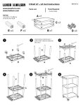
Boolean Solids Tutorial
Introduction
The CADMAX Solid Master Tutorial is a great way to learn about the benefits of constructive (boolean)
solid modeling with CADMAX. We have assembled four typical parts that you will be able to construct
using CADMAX Solid Master. Each part should take between 20-40 minutes to complete.
The tutorial assumes that you already have some familiarity with CADMAX. In you are unfamiliar
with CADMAX, review the Getting Started section first. Here are several additional suggestions before
getting started:
!
In the tutorial there are several conventions that are used with text. The text Draw > Circle >
Center Radius means to click on the Draw menu, hold the cursor over the Circle function until the
Circle sub-menu pops, then click on Center Radius.
!
When you see a statement that starts with the word “set”, this means you are to set a modifier
value in the currently displayed Function box. For example, in the Line function box, you will see
a -Connect? modifier. When you see the statement, “Set -Connect? to off”, this means you
should set it off by clicking on the word Connect if it isn’t already off.
!
Sometimes you will be asked to set a specific value for a modifier. For example, in the Circle
Function box you will see a modifier called -Radius? with a combo box below it and a history
arrow. When you see the statement, “Set -Radius? to .25”, this means you should click in the
-Radius? text field and type in the value or use the history arrow to select previous value.
!
When an instruction includes an arrow key ( 6 7 8 9) followed by a number, hold down the Ctrl
key before pressing the specified arrow. For example, <Ctrl+6>1 means hold down the Ctrl key
and press 6, then release the keys and press 1. After you type in the value, press Enter.
!
Context sensitive prompts are available for each function in the message area at the bottom of the
screen. Help is available buy pressing F1.
!
In the tutorial, we recommend when you should zoom in or out on the drawing to get better views
of your work. In addition to our recommendations, you should feel free to use the View menu to
Zoom around the drawing as you feel is appropriate. Press F10 to go to previous zooms or F11 to
make a new zoom or use the View shortcut icons on the right side of the display.
!
To load a specified drawing, press F4 to Open a drawing. The drawings that you will be asked to
open are located in the \SAMPLES sub-folder under the folder that you installed CADMAX.
CADMAX User's Manual
Boolean Solids Tutorial / 1
27-Pin DIN Connector
In this section, you will use CADMAX Solid Master to build a 27-pin DIN connector. Your final part
should look similar to this:
2 / Boolean Solids Tutorial
CADMAX User's Manual
Draft Connector Base Profile
1. Open the drawing CONNECT and click on Edit > Surfaces and boolean solids or
click on the 3D icon on the Ribbon bar.
2. Starting in the top view, draft the profile shown at right.
3. Click on Draw > Line, and set -Connect? ’on’. Click at a start point in the lower left
side of the top view. Then at the keyboard enter:
<Ctrl+6>2.2
<Ctrl+PageDown>.125
<Ctrl+7>.1875
<Ctrl+PageDown>.44
<Ctrl+7>.1875
<Ctrl+PageDown>.75
4. Right click, then click on Select All In, and
using a rubberband box, fully enclose all of the
geometry except the 2.2" line.
5. Click CPL > Align to View, click on the side
view to align the CPL to the side view (lower
right view) .
6. Click Modify > Mirror, and set -Move
Which? to ‘Copy’. To mirror the selected
geometry about the midpoint of the 2.2" line,
click on the Midpoint snap icon in the Quick
Snap tool bar, then click anywhere on the 2.2"
line.
7. Right click, then click Clear.
8. Click Draw > Line, and draw a line to close
the profile as in the figure to the right.
Extrude Connector Profile
1. Right click, then click Select All In, and using a
rubberband box, fully enclose the entire profile.
2. Click Modify > Sweep > Linear Surfaces,
set -Sweep? to ‘ends only’, and -Make Solids?
‘on’. Click anywhere as a pick up point, then
type <Ctrl+9>.60 to extrude the profile.
CADMAX User's Manual
Boolean Solids Tutorial / 3
Add Fillets to Connector Base
1. Zoom in on the isometric view using the Quick
Tool bar on the right side of the screen and
click Resume when done or click on the next
function.
2. Click Hidden dashed in the Quick 3DView
tool bar, then click on the isometric view.
3. Click Modify > Corner > Fillet/Chamfer
Advanced, set -Radius? to ‘.1875', and set
-Type? To ‘Fixed radius’. Click on Add, then
click on the edges identified by the bullets in
the illustration. The specified edges will turn
red.
4. Click Done in the Fillet/Chamfer Advanced
Function box to apply the specified fillets.
5. Set -Radius? to ‘.03125'. Click Add, then select
the four edges at the lower corners. The
illustration shows the edges for two corners.
Select the opposite two corners to get all four
edges. Zoom in on the drawing in the isometric
view to select the far edges.
6. Click Done to apply the specified fillets.
Note: You change the orientation of a view or
how a view is displayed in order to see
boundaries that are not visible in a view. The
Quick View menu on the right side of the screen
contains functions to change a view to
wireframe, hidden, hidden-dashed, shaded or unshaded. Following are the icons that
permit you to change how a view is displayed. To operate these functions, click on the
icon, then click on the view to change.
Wireframe view
Shaded View
Hidden view
Unshaded View
Hidden dashed view
4 / Boolean Solids Tutorial
CADMAX User's Manual
To rotate a view, use dynamics. Click on the Dynamic View Roll icon, then click on
the view to roll, then click on roll about point to start the roll. Normally, the roll about
point is on geometry in the model. Drag the cursor in the direction of the roll and click
again to anchor the view at the new orientation. Use Previous View to return the view
to its original orientation.
Dynamic view roll
Previous View
7. Set -Radius? to ‘.03125'. Click Add, then
select the three edges shown in the illustration
with a single radius of .0312.
8. Set -Radius2? to ‘.1875' and set -Type? to
‘Variable linear’ for a variable linear radius
fillet which will start at .0312 and end at a
radius of .1875. Click Add, the select the
next two edges indicated in the illustration
near the location of the bullets on the line.
Note: When applying a variable radius fillet,
the -Radius? is applied to the end of the edge
that is closest to the point you select and the
opposite end uses -Radius2?.
9. Set -Radius? to ‘.1875' and Set -Radius2? to
‘.3'. Click Add, then select the last two edges
indicated in the illustration near the
location of the bullets on the line.
10. Click Done to apply the specified fillets.
11. Repeat Steps 7-10 on the other side of the
connector body.
12. Click on the Hidden icon in the Quick 3DView
tool bar, then click on the isometric view to
make it hidden.
CADMAX User's Manual
Boolean Solids Tutorial / 5
Place initial holes for post holes
1. Zoom to the front view.
2. Click 3DView > View Control > Orient, set
-Angle? to ‘180' and set -Rotate Axis? to ‘model
x’. Click on the front view to get a rear view of
the connector.
3. Using the illustration as a guide, right click,
then click Select Element and select the line
indicated by the bullet on the left edge of the
connector.
4. Right click, then click Move. Pick anywhere as
a pick up point and type <Ctrl+6>.15.
5. Click Select > Clear or right click, then click
Clear.
6. Using the illustration as a guide, right click, then
click Select Element. Select the line on the
right edge of the connector.
7. Right click, then click Move. Pick anywhere as
a pick up point and type <Ctrl+7>.15.
8. Click Select > Clear or right click, then click
Clear.
9. Click Draw > Circle > Center Radius, set
-Radius? to ‘.15' and -Circle Plane? to ‘view’.
10. Click on the Quick Snap Midpoint icon, then
click on one of the lines just added to insert the
circle on the midpoint of the construction line.
Repeat this step for the other line.
11. Select the two construction lines just added and
Erase them.
6 / Boolean Solids Tutorial
CADMAX User's Manual
Extrude holes
1. Select the two circles just added.
2. Click on Modify > Sweep > Linear Surfaces,
click anywhere in the view as a pick up point and
type <Ctrl+PageDown>.375 as the put down
point.
3. Click Select > Select > Solid, and click on the
two objects just added.
4. Click Draw > Solid > Add, set -Remove
Excess Edges? ‘on’, and click on the main
connector body to add the selected solids to the
connector.
5. Click Draw > Circle > Center Radius, set
-Radius? to ‘.15', set -Auto Select? ‘on’ by
clicking on the Auto Select icon on the Ribbon
bar.
6. Click on the Center point snap icon in the
Quick Snap tool bar, then click on one of circles
at the top of the posts in the front view to insert
the circle. Repeat this step on the other side.
Set -Auto Select? ‘off’.
7. Click on Modify > Sweep > Linear Surfaces,
click anywhere in the view as a pick up point and type
<Ctrl+PageDown>.25 as the put down point.
8. Click Select > Select > Solid, and click on the two
objects just added.
9. Click Draw > Solid > Subtract, and click on the main
connector body.
CADMAX User's Manual
Boolean Solids Tutorial / 7
Cut holes
1.
Click Draw > Circle > Center Diameter, set
-Diameter? to ‘.1875', set -Auto Select? ‘on’ in
the Ribbon bar.
2. Click on the Center point snap icon, then click
on one of circles at the top of the posts in the
front view to insert the circle. Repeat this step
on the other side. Set -Auto Select? ‘off’.
3. Click on Modify > Sweep > Linear Surfaces,
click anywhere in the view as a pick up point and
type <Ctrl+PageUp>1 as the put down point.
4. Click Select > Select > Solid, and click on the
two objects just added.
5. Click Draw > Solid > Subtract, and click on
the main connector body.
Draft connector profile
1. Click 3DView > View Control > Orient, set
-Axis? to ‘model x’, and set -Angle? to ‘180'.
Click on the front view to rotate the view back to
being a front view.
2. Click Draw > Point > Intersection, then in the
front view click on the left vertical line, and the
top horizontal as illustrated by the bullets in the
view to the right. This will place a point at the
intersection of the two lines.
3. Click Draw > Line, and click on the point that
was just inserted into the drawing to set the point
as the reference point.
4. Click Draw > Line again, then type:
<Ctrl+6>.375,<Ctrl+9>.17 for the first
point and <Ctrl+6>1.45 for the second
point.
8 / Boolean Solids Tutorial
CADMAX User's Manual
5. Select the line just created, right click then
click Copy. Click anywhere as the pick up
point, then type <Ctrl+9>.26.
6. Right click, then click Clear.
7. Click Draw > More Lines > 1 Pt
Construction, set -Construction Size? to ‘use
length’, set -Angle? to ‘-80', and set -Length?
to ‘1'. Click on the left endpoint of the upper
horizontal line in the front view to insert a line.
Set -Angle? To ‘-100', and click on the right
endpoint of the upper horizontal line.
8. Click Modify > Corner > Fillet Curve, set Trim? to ‘both’ and set -Radius? to ‘none’.
Click on the bottom horizontal line and one of
the angled lines to trim them to a corner.
Repeat this sequence on the opposite side to
complete the outline.
Draft connector holes
1. Click Draw > Circle > Center Diameter, set
the -Diameter? to ‘.0625', and place the circle
at the point indicated in the illustration.
2. Right click, click Select, and select the circle,
right click again and click Copy. Click
anywhere in the view as a pick up point and
type:
<Ctrl+6>.075,<Ctrl+9>.075
<Ctrl+6>.05,<Ctrl+9>.11
3. Click Modify > Erase Element to erase the
original circle, then click on the construction
point in the upper left of the front view to
erase it.
4. Click Select > Select Element, and select
the two circles just inserted in the drawing.
5. Click CPL > Align to View, and click on
the front view.
CADMAX User's Manual
Boolean Solids Tutorial / 9
6. Click Modify > XYZ Step, set the following modifier values:
-X Step Size? = .1
-# X Steps? = 14
-Y Step Size? = 0
-# Y Steps? = 1
-Z Step Size? = 0
-# Z Steps? = 1
7. Click the Center point snap icon, touch the
upper circle as the pick up point for the array,
then press Enter to use the same point as the
grid start point.
8. Erase the two original circles and the extra
circle on the bottom row.
9. Click Select > Filters > All Off. Click
Select > Filters > Edit, and Set -Lines? ‘on’,
-Arcs? ‘on’. If necessary, click on the Use
Filter icon in the Ribbon bar to depress it and
set it on, if it’s already depressed, leave it
alone.
10. Right click, and click Select All In. Working
in the front view, place a rubberband box
around the profile of the 27-Pin DIN profile
that was just constructed.
11. Click Select > Filters > All On.
12. Click on Modify > Sweep > Linear
Surfaces, click anywhere in the view as a pick
up point and type <Ctrl+PageUp>.22 as the
put down point.
13. Use Previous in the Quick View tool bar to
zoom back out to the view of all four views.
14. Click Draw > Solid > Add, set -Remove
Excess Edges? ‘on’, and click on the main
connector body and the 27-pin connector to join
the two solids.
10 / Boolean Solids Tutorial
CADMAX User's Manual
Fillet connector
1. Click on Select > Select Element and select
the edges shown in the illustration.
Three edges are easy to select. Click
Dynamic View Roll in the Quick 3DView tool
bar, click on the isometric view then click on
a point on the connector to roll about. Rotate
the view until you can see the hidden edge,
then click to place the view.
Right click, click on Select Element and
select the fourth edge.
2. Click Previous 3DView in the Quick 3DView
tool bar, then click on the isometric view to
return it to its original position.
3. Click Modify > Corner > Fillet Selected
Edges, set -Radius? to ‘.0625', click Finish
to apply the fillet to the selected edges.
4. Right click, click Select Element and select
the edge shown by the bullet in the
illustration. Although only one edge was
selected, CADMAX will apply the fillet to the
entire boundary automatically.
5. Click Modify > Corner > Fillet Selected
Edges, set -Radius? to ‘.03125', click Finish
to apply the fillet to the selected edges.
6. Save the drawing as BODY if you are not
running Test Drive. If you are running Test
Drive, you can make a Snapshot of your work
by clicking File > Snapshot.
CADMAX Solid Master Tutorial
11