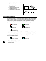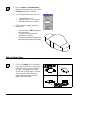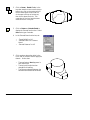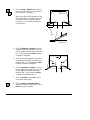
1
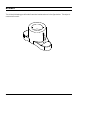
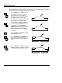
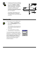
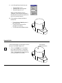
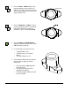
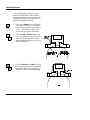
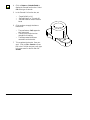
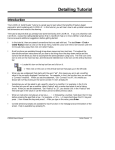
Solids Tutorial
Introduction
The CADMAX Solid Master Tutorial is a great way to learn about the benefits of feature-based
parametric solid modeling with CADMAX. We have assembled several typical parts that you will be
able to construct using CADMAX Solid Master. Each part should take between 20-40 minutes to
complete.
The tutorial assumes that you already have some familiarity with CADMAX. If you are unfamiliar with
CADMAX, review the Getting Started section first in CADMAX Help or in the CADMAX Users Manual.
Here are several additional suggestions before getting started:
!
In the tutorial, there are several conventions that are used with text. The text Draw > Circle >
Center Radius means to click on the Draw menu, hold the cursor over the Circle function until the
Circle sub-menu pops, then click on Center Radius.
!
Most functions are available through drop-down menus and icon tool bars. Throughout the
tutorials the written instructions tell you how to do things from the drop-down menus and the
icons to the left show you how to accomplish the same operation using icons. The first icon is the
icon to click on the main tool bar, and the second indented icon is the icon on the vertical function
bar.
< Locate this icon on the top tool bar and click on it.
< Then click on this icon on the vertical tool bar that pops up on the left side.
!
When you see a statement that starts with the word “set”, this means you are to set a modifier
value in the currently displayed Function box. For example, in the Line function box, you will see
a -Connect? modifier. When you see the statement, “Set -Connect? to off”, this means you
should set it off by clicking on the word Connect if it isn’t already off.
!
Sometimes you will be asked to set a specific value for a modifier. For example, in the Circle
Function box you will see a modifier called -Radius? with a combo box below it and a history
arrow. When you see the statement, “Set -Radius? to .25”, you should click in the -Radius? text
field and type in the value or use the history arrow to select previous value.
!
When an instruction includes an arrow key (6 7 8 9) followed by a number, hold down the Ctrl key
before pressing the specified arrow. For example, <Ctrl+6>1 means hold down the Ctrl key and
press 6, then release the keys and press 1. After you type in the value, press Enter.
!
Context sensitive prompts are available for each function in the message area at the bottom of the
screen. Help is available buy pressing F1.
CADMAX User's Manual
Solids Tutorial / 1
!
In the tutorial, we recommend when you should zoom in or out on the drawing to get better views
of your work. In addition to our recommendations, you should feel free to use the View menu or
the Quick View toolbar to zoom around the drawing as you feel is appropriate. Press F10 to go to
previous zooms or F11 to make a new zoom.
!
To load a specified drawing, press F4 to Open a drawing. The drawings that you will be asked to
open are located in the \SAMPLES sub-folder under the folder that you installed CADMAX.
2 / Solids Tutorial
CADMAX User's Manual
Bracket
The third solid drawing you will model is another bracket as shown in the figure below. This object is
constructed in metric.
CADMAX User's Manual
Solids Tutorial / 3
Opening a Sketch
1.
Open the drawing
FEATURE_METRIC.CXS from the
/SAMPLES folder which is a subfolder
under the folder you installed
CADMAX.
2.
Click on Edit > Feature Modeling or
click on the Feature Modeling icon on
the Ribbon bar.
3.
Click on Edit > Sketch or click on the
Sketch icon on the ribbon bar to start a
new sketch.
4.
In the Work Plane function box, set the
-Method? to ‘View’, -Adjustment? to
‘None’ and click on the front view (lower
left). Now, no matter which view you
work in, as you sketch your object, the
geometry will always be oriented to the
front view.
5.
Click on Draw > Sketch Line on the
Sketch function bar. Working in the front
view, draw the profile shown using the
full view. Use dynamic construction lines
to make the lines horizontal and vertical.
6.
Click on Draw > Sketch Arc, then click
on the end-point of one of the lines, click
on a middle point for the arc, then click
on the opposite end point to complete
the profile as shown.
4 / Solids Tutorial
CADMAX User's Manual
Adding Dimensions
Dimensions are used to make the geometry the desired size. CADMAX does not require
that you add dimensions before you extrude the model. You can always return to the sketch
and add dimensions or change the sketch later in the design.
1.
Click on Dimension > Radial. Click on
the arc, drag the cursor to the desired
text position and click to place the
dimension. Type in 50 and press Enter.
This assigns a value of 50 for the
dimension and automatically resizes the
arc according to the assigned value.
You can always change this value at a
later time using the Equation function.
For example, click on Dimension >
Equation then wave the cursor over the
radius dimension until it highlights, click
on the dimension and type in 35 and
press Enter.
Click on Undo or press Ctrl+Z to reset
the arc radius back to 50.
2.
Click on Dimension > Horizontal. Add
the dimensions shown in the figure, by
placing the dimension and entering its
value.
3.
Click on Dimension > Vertical. Add the
dimension shown in the figure, by placing
the dimension and entering its value.
CADMAX User's Manual
Solids Tutorial / 5
4.
Constrain the center point of the R50 arc
to the midline of the horizontal 90 length
line. Click on Constrain > Connect,
wave the cursor over the arc and then
click on its center point. Then wave the
cursor over the midpoint of the 90
horizontal line until the dynamic
construction lines pop-up, click anywhere
on the vertical construction line (do not
click on the midpoint)
The message, “Well-defined; Correct
number of dimensions” is displayed.
This means that the profile has been fully
constrained.
Extrude the Profile
The first feature in a part is called the base.
1.
Click on Feature > Extrude Sketch or
click on the Extrude Sketch icon on the
top tool bar.
The Extrude Base dialog box appears so
you can specify the type and distance of
the extrusion.
2.
Set -Extrude Distance? to ‘44' and
-Extrude Extent? to ‘Distance Above’.
The extrusion takes place toward the point
that you click. The direction of the extrusion
is defined by the side of the sketch that you
click on. Working in the top view (top left),
if you click above the profile, then the
extrusion will take place in that direction.
Clicking below the profile brings the
extrusion toward you.
6 / Solids Tutorial
CADMAX User's Manual
3.
In the top view, click anywhere below the
profile. Notice that:
•
•
•
The new feature, Base1, appears in
the Feature tree.
The top level function bar has
changed for Modeling.
The sketch was extruded in each
view.
Set the Display Preferences
You change the orientation of a view or how a view is displayed in order to see boundaries
that are not visible in a view. The 3D Quick View tool bar on the right side of the screen
contains functions to change a view to wireframe, hidden, hidden-dashed, shaded or
unshaded. Following are the icons that permit you to change how a view is displayed. To
operate these functions, click on the icon, then click on the view to change.
Wireframe View
Shaded View
Hidden View
Unshaded View
Hidden dashed View
To rotate a view, use dynamics. Click on the Dynamic View Roll icon, then click on the view
to roll, then click on a roll about point to start the roll. Normally, the roll about point is on
geometry in the model. Drag the cursor in the direction of the roll and click again to anchor
the view at the new orientation. Use Previous View in the 3D Quick View toolbar to return
the view to its original orientation.
Dynamic View Roll
1.
Previous View
Click on Hidden in the 3D Quick View
tool bar, then click on the isometric view
to make it hidden.
CADMAX User's Manual
Solids Tutorial / 7
2.
Click on Hidden-dashed in the 3D Quick
View tool bar, then click on the front,
top, and side views to make each view
hidden-dashed.
3.
If some of the geometry is outside the
view window, you can easily pan the
window. Click on Dynamic View Move
in the 3D Quick View tool bar. Click on
the view to move. Then, click on the
point to move the view about. Click
again to place the view at the new
location. The graphic to the right shows
the geometry in the top view moved up.
Sketch Top Profile
In the next series of steps you will sketch a
profile of the part looking down on it from
the top using the base geometry to constrain
the top profile.
1.
Click on the Sketch icon on the ribbon
bar to start a new sketch.
2.
In the Work Plane function box, set the
-Method? to ‘View’, -Adjustment? to
‘None’ and click on the top view. It is
not necessary to set a depth because the
extrude feature will be ‘Through All’ and
the depth of the work plane will have no
effect.
3.
Zoom in on the top view.
4.
Click on Draw > Sketch Line. Set
-Connect? to ‘on’ and set -Smart Grid?
to ‘off’ to turn the dynamic construction
lines off. Working in the top view, draw
the profile shown.
Draw this profile
Make sure the end points of the lines
aren’t on any geometry. This will assign
constraints that will prevent you from
drawing this profile correctly.
8 / Solids Tutorial
CADMAX User's Manual
5.
Click on Draw > Sketch Fillet. Set
-Chain? to ‘on’.
Note: When -Chain? is ‘on’, then each
succeeding fillet after the first fillet will
have the same radius as the first fillet and
will be constrained equal radius.
Assigning a radius dimension to any fillet
in the chain will effect all fillets
constrained equal radius. Clicking on
another function breaks the chain.
Click on the top or bottom intersection,
drag the cursor toward the center until a
fillet echo shows and click to place the
fillet. Wave the cursor over the opposite
intersection until the fillet echo shows,
click once to place the fillet as shown.
Fillets
Note: When -Chain? is ‘on’, each
succeeding fillet only requires a single
click since the radius was already
defined. If the intersection for a fillet
isn’t easy to identify, you can optionally
click on the lines or arcs near the
intersection.
6.
Click on Draw > Sketch Fillet again to
restart the chain. Click on the left or
right intersection, drag the cursor toward
the center until a fillet echo shows and
click to place the fillet. Wave the cursor
over the opposite intersection until the
fillet echo shows, click once to place the
fillet as shown.
Fillets
Note: Using the fillet function constrains
the end points of the arcs and line
tangent. It is not necessary to explicitly
define this constraint.
In the next series of steps, you will use the
geometry from the base feature to assign
constraints to the profile, thereby creating a
relationship between them. You are going to
make the top and bottom fillets tangent to
CADMAX User's Manual
Solids Tutorial / 9
the top and bottom edges and then make the
fillets concentric.
7.
Click on Constrain > Tangent, click on
the top fillet, then click on the top edge.
Step2: Click on edge
Step1: Click
on fillet
8.
Now repeat the sequence for the bottom
arc and the bottom edge.
Arcs are tangent
to the edges
9.
Click on Constrain >
Parallel/Concentric and click on the top
and bottom arcs to make them
concentric. This constraint forces the arc
to have a radius equal to one-half the
width of the base feature.
Arcs have been
constrained to
be concentric
Step 2: Wave cursor
over midpoint of line
10. In this step, you are going to constrain
the center of the top and bottom arcs to
the midline of the base feature. Click on
Constrain > Connect, set -Smart Grid?
‘on’, click on the center point of the top
or bottom arc, wave the cursor over the
midpoint of the horizontal line to display
the vertical construction line, click
10 / Solids Tutorial
Step1: Click on
arc center point
Step3: Click
anywhere on vertical
construction line
CADMAX User's Manual
anywhere on the construction line (do
not click on geometry).
11. Click on Dimension > Radial. Click on
the left arc, drag the cursor to the
desired text position and click to place
the dimension. Type in 12 and press
Enter.
12. In the final step, you are going to connect
the midpoint of the left and right arcs to
the midpoint of the vertical lines on the
edges of the base feature. Click on
Constrain > Connect, wave the cursor
over one of the arcs, click on the
midpoint (not the center point) of the
arc, then wave the cursor over the
corresponding vertical line and click on
the midpoint of the line.
Repeat this sequence for the opposite
arc, completing the profile.
Extrude Profile
In the next sequence, you will extrude the
profile and leave the common elements
between the two features.
1.
Press F10 or click on Previous in the
Quick View tool bar to display the four
views.
CADMAX User's Manual
Solids Tutorial / 11
2.
Click on Feature > Extrude Sketch to
display the Extrude function box. Select
Common as the type of extrude.
3.
In the Extrude Boss function box, set:
•
•
•
4.
-Target Solids? to ‘All’
-Extrude Extent? to ‘Through All’
-Extrude Distance? is not used
Click anywhere to apply the feature.
Notice that:
•
•
•
The new feature, Share1, appears in
the Feature tree.
The top level function bar has
changed for Modeling.
The common elements between the
two features has been left as shown.
Add a Cylinder Boss
1.
Click on the Sketch icon on the ribbon
bar to start a new sketch. In the Work
Plane function box, set the -Method?
to ‘View’, -Adjustment? to ‘Origin’,
click on the top view, then in the front,
side, or isometric view click on the
bottom edge of the part to set the
depth of the work plane.
12 / Solids Tutorial
CADMAX User's Manual
2.
Click on Draw > Sketch Circle. In the
top view, wave the cursor over the top or
bottom arc, click on the center point of
the arc and drag the cursor until the
circle snaps to the top or bottom arc,
then click to place the circle. This
constrains the circle to have the same
radius as the arc in the part.
3.
Click on Feature > Extrude Sketch to
display the Extrude function box. Select
Boss as the type of extrude.
4.
In the Extrude Boss function box, set:
•
•
•
5.
Insert circle
-Target Solids? to ‘All’
-Extrude Extent? to ‘Distance
Above’
-Extrude Distance? to ‘42'
Click anywhere above the object in the
front, side, or isometric view to apply the
feature. Notice that:
•
•
•
CADMAX User's Manual
The new feature, Boss1, appears in
the Feature tree.
The top level function bar has
changed for Modeling.
The common elements between the
two features has been left as shown.
Solids Tutorial / 13
Add Fillets
Add fillets to the top of the base.
1.
Zoom in on the isometric view. In the
Quick 3D View tool bar on the right edge
of the display, click on Dynamic View
Roll, then click on the isometric view,
then click on a point in the center of the
view as the roll about point. Slowly drag
the cursor, moving the model until you
can see both sides of the model. Click
again to anchor the view.
2.
Click on Select > Select Surface. Click on
the surfaces shown in the figure.
The Select Surface function is used to
select only surfaces and their edges.
Notice that the surfaces highlight in red
as you move the cursor over them,
identifying which one will be selected.
Once a surface is selected, its boundary
will turn yellow and a surface tag will
display.
3.
Click on Select > Unselect Element.
Click on the edges shown in the figure.
They will turn back to their original color
showing that they are no longer selected.
14 / Solids Tutorial
CADMAX User's Manual
4.
Click on Feature > Fillet, Fixed. Set
-Fillet Radius? to ‘1' and click Finish to
apply the fillet feature to the selected
edges.
5.
In the Quick 3D View tool bar on the
right edge of the display, use Previous
View to change the isometric view back to
its original orientation. Click on
Previous View, then click on the isometric
view.
6.
Click in Previous or press F10 to return
back to the four views.
Add Support Ribs
Add support ribs at an 78 degree angle. The
work plane will be parallel to the front view
and the depth of the plane will be in the
center of the part. Once the rib profile is
established, you will use a midplane extrude
to apply the feature.
1.
Click on the Sketch icon on the ribbon
bar to start a new sketch. Set the
-Method? to ‘View’ and -Adjustment?
to ‘Origin’. Click on the front view,
then click on the Center snap icon on
the Quick Snap tool bar, wave the
cursor over the circle until the work
plane echo pops to the center of the
large circle, then click to set the depth
of the work plane.
2.
Zoom in on the front view.
CADMAX User's Manual
Solids Tutorial / 15
3.
Click on Draw > Sketch Line. Working
in the front view, draft a profile similar to
the one shown in the figure.
Profile
Start the profile at the intersection of the
fillet radius shown in the detail view. Use
the same point on the opposite side of
the profile. This constrains these points
to this position.
Detail
Detail
Snap to top of
the fillet radius
4.
Click on Dimension > Angular. Click on
the bottom horizontal line, then click on
the left angular line and click to place the
text. Type ‘78' and press Enter to assign
an angle of 78 degrees.
5.
Click on the right angular line, then click
on the bottom horizontal line and click to
place the text. Type ‘78' and press Enter
to assign an angle of 78 degrees.
6.
Click on Dimension > Vertical. Click on
the top edge of the profile, then click on
the top edge of the model and click to
place the text. Type ‘4' and press Enter
to assign a vertical distance of 4.
7.
Click on Previous or press F10 to zoom
out to the 4 model views.
8.
Click on Feature > Extrude Sketch to
display the Extrude function box. Select
Boss as the type of extrude.
16 / Solids Tutorial
CADMAX User's Manual
9.
In the Extrude Boss function box, set:
•
•
•
-Target Solids? to ‘All’
-Extrude Extent? to ‘Midplane’
-Extrude Distance? to ‘4'
When -Extrude Extent? is set to
‘Midplane’, then the profile extrudes in
both directions from the work plane one
half the -Extrude Distance?.
10. Click anywhere to apply the feature.
Notice that:
•
•
•
The new feature, Boss2, appears in
the Feature tree.
The top level function bar has
changed for Modeling.
The ribs have been added as shown.
Insert a Hole
In the following steps, you will insert a hole in
the top of the model a depth of 15.
1.
Set the work
plane to this face
Click on the Sketch icon on the ribbon
bar to start a new sketch. In the Work
Plane function box, set the -Method? to
‘Face’, -Adjustment? to ‘None’ and click
on the top surface of the model.
CADMAX User's Manual
Solids Tutorial / 17
2.
Click on Draw > Sketch Circle. In the
top view, wave the cursor over the 22
radius circle, click on the center point of
the circle and drag the cursor out, click to
place a smaller circle.
3.
Click on Dimension > Radial. Click on
the circle, drag the cursor to the desired
text position and click to place the
dimension. Type in 14 and press Enter.
4.
Click on Feature > Extrude Sketch to
display the Extrude function box. Select
Cut as the type of extrude.
5.
In the Extrude Cut function box, set:
•
•
•
6.
Insert circle
-Target Solids? to ‘All’
-Extrude Extent? to ‘Distance
Above’
-Extrude Distance? to ‘15'
Click anywhere below the work plane in
the front view to apply the feature.
Notice that:
•
•
•
18 / Solids Tutorial
The new feature, Cut1, appears in
the Feature tree.
The top level function bar has
changed for Modeling.
The hole has been inserted into the
top of the model.
CADMAX User's Manual
Cut Away Excess
In the following steps, you will cut away
excess from the bottom of the bracket by
inserting a 42 radius circle in the front view
using the center point of the 50 radius arc
and cutting through the bracket.
1.
Click on the Sketch icon on the ribbon
bar to start a new sketch. In the Work
Plane function box, set the -Method? to
‘View’, -Adjustment? to ‘None’, and
click on the front view of the model.
2.
Click on Draw > Sketch Circle. In the
front view, wave the cursor over the 50
radius arc, click on the center point of
the arc and drag the cursor out, click to
place a smaller circle.
3.
Click on Dimension > Radial. Click on
the circle, drag the cursor to the desired
text position and click to place the
dimension. Type in 42 and press Enter.
CADMAX User's Manual
Solids Tutorial / 19
4.
Click on Feature > Extrude Sketch to
display the Extrude function box. Select
Cut as the type of extrude.
5.
In the Extrude Cut function box, set:
•
•
•
6.
Click anywhere to apply the feature.
Notice that:
•
•
•
7.
-Target Solids? to ‘All’
-Extrude Extent? to ‘Through All’
-Extrude Distance? doesn’t need to
be set
The new feature, Cut2, appears in
the Feature tree.
The top level function bar has
changed for Modeling.
The excess material has been
removed from the bracket.
This completes the bracket. Save your
work. Click on File > Save As or press
F3. In the Full Path text entry area, type
in the new name for the file and click
Save As.
20 / Solids Tutorial
CADMAX User's Manual