1
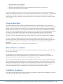
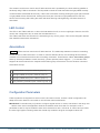
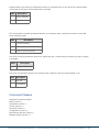
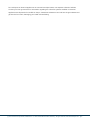
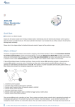
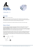
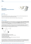
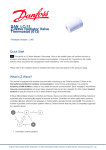
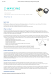
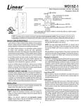
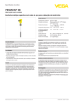
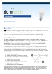
TKB_TZ65-D
Z-Wave Dual Paddle Wall
Dimmer
Firmware Version : 1.3
Quick Start
A This device is a Z-Wave actuator. To include the device into the network, turn the controller into the
inclusion mode and then press the upper or lower part of the paddle of the device. The device is now ready
to work.
Please refer to the chapters below for detailed information about all aspects of the products usage.
What is Z-Wave?
This device is equipped with wireless communication complying to the Z-Wave standard. Z-Wave is the
international standard for wireless communication in smart homes and buildings. It is using the
frequency of 868.42 MHz to realize a very stable and secure communication. Each message is reconfirmed
(two-way communication) and every mains powered node can act as a repeater for other nodes (meshed
network) in case the receiver is not in direct wireless range of the transmitter.
Z-Wave differentiates between Controllers and Slaves. Slaves are either sensors (S) transmitting metered or
measured data or actuators (A) capable to execute an action. Controllers are either static mains powered
controllers (C) also referred to as gateways or mobile battery operated remote controls (R). This results in a
number of possible communication patterns within a Z-Wave network that are partly or completely supported
by a specific device.
1. Controllers control actuators
2. Actuators report change of status back to controller
3. Sensors report change of status of measured values to controller
(c) 2012 Z-Wave Europe GmbH, Goldbachstr. 13, 09337 Hohenstein-Ernstthal, Germany, All rights reserved, www.zwaveeurope.com - pp 1
4.
5.
6.
7.
Sensors directly control actuators
Actuators control other actuators
Remote controls send signals to static controllers to trigger scenes or other actions
Remote controls control other actuators.
There are two different role a controller can have. There is always one single primary controller that is managing the
network and including/excluding devices. The controller may have other functions - like control buttons - as well. All other
controllers don't manage the network itself but can control other devices. They are called secondary controllers. The
image also shows that its not possible to operate a sensor just from a remote control. Sensors only communicate with
static controllers.
Product description
The TZ65-D dual wall switch is switching attached loads and is controlled either by the local switching
paddle or remotely via the Z-Wave wireless protocol. It is included and controlled in a Z-Wave network by a
remote control, a wireless control centre or any other kind of Z-Wave controller including a PC-software.
Beside the local switch the unit can control other Z-Wave units remotely in up to three additional Z-Wave
groups, which are associated with this device. Tipping one time or two times the switching paddle performs
the control. The left paddle controls the local load while the right paddle remotely controls Z-Wave
associated devices only. The association of further Z-Wave devices needs to be done by a Z-Wave
controller. The unit is powered by 230V and needs a pattress box with 230 V power wires for installation.
The unit is shipped completely with electronics, switching paddle and mounting frame in arctic white
HomePro style, which can be replaced by another mounting frame of the HomePro switching series. The
unit is designed for use within a 3-wire system, which means that a neutral wire (blue) is needed for
operations.
Attention: The Switch does not fit in a german 60mm pattress box!
Before Device is installed
Please read carefully the enclosed user manual before installation of the radio-actuator, in order to ensure
an error-free functioning.
ATTENTION: only authorized technicians under consideration of the country-specific installation
guidelines/norms may do works with 230?Volt mains power. Prior to the assembly of the product, the
voltage network has to be switched off and ensured against re-switching.
The product is permitted only for proper use as specified in the user manual. Any kind of guarantee claim
has to be forfeited if changes, modifications or painting are undertaken. The product must be checked for
damages immediately after unpacking. In the case of damages, the product must not be operated in any
case. If a danger-free operation of the equipment cannot be assured, the voltage supply has to be
interrupted immediately and the equipment has to be protected from unintended operation.
Installation Guidelines
The TZ65-D wall mounted dimmer needs a pattress box with 230 V power wires for installation. It does not
fit into European wall boxes with 60 mm diameter.
(c) 2012 Z-Wave Europe GmbH, Goldbachstr. 13, 09337 Hohenstein-Ernstthal, Germany, All rights reserved, www.zwaveeurope.com - pp 2
1. To install the wall dimmer first remove the paddle using a small screw driver.
2. Afterwards remove the four screws through the retaining ring holding the trim ring to the mounting
plate. This will allow the removal of the trim ring. When removing the trim ring make sure not to bend
or disrupt the shape of the antenna wire.
3. Wire the product according to the schematics. The two wired from the mains distribution panel are
directly connected to the inserts contacts N and L. The contact L' is the switched load output and
needs to be connected to the cable of the load.
4. Install the product in the wall box.
5. Reinstall the trim ring and the retaining ring with the four screws. Mind the arrow on the inserts top
side showing the mounting direction of the insert.
6. Return the switching paddle by pushing it into the mounting frame. Make sure the LED window is also
towards the stamped word "€œBottom"€• on the retaining ring.
Behavior within the Z-Wave network
I
On factory default the device does not belong to any Z-Wave network. The device needs to join an
existing wireless network to communicate with the devices of this network. This process is called Inclusion.
Devices can also leave a network. This process is called Exclusion. Both processes are initiated by the
primary controller of the Z-Wave network. This controller will be turned into exclusion respective inclusion
mode. Please refer to your primary controllers manual on how to turn your controller into inclusion or
exclusion mode. Only if the primary controller is in inclusion or exclusion mode, this device can join or leave
the network. Leaving the network - i.e. being excluded - sets the device back to factory default.
If the device already belongs to a network, follow the exclusion process before including it in your network.
Otherwise inclusion of this device will fail. If the controller being included was a primary controller, it has to
be reset first.
The device is included and excluded by a single click on the switch when the controller is in inclusion resp.
exclusion mode.
Operating the device
(c) 2012 Z-Wave Europe GmbH, Goldbachstr. 13, 09337 Hohenstein-Ernstthal, Germany, All rights reserved, www.zwaveeurope.com - pp 3
The actuator can be set to control other Z-Wave devices and is operated by the local switching paddles or
wirelessly using Z-Wave commands. The left paddle controls the local load while the right paddle remotely
controls Z-Wave associated devices only. If the insert is mounted correctly pushing the upper part of the left
or right paddle will turn ON the load. Pushing the lower part of the left or right paddle will turn OFF the
electric load. Pressing and holding the switch will allow dimming and brightening of Z-Wave dimmers if
associated.
LED Control
The LED on the TZ65-D will turn on when the load attached is off, to act as a night light. However, the LED
can be user configured to turn on when the load attached is on.
The TZ65-D will flicker its LED when it is transmitting to any of its 4 groups. This can be changed if desired.
See "€œLED transmission indication"€•.
Associations
A
Z-Wave devices control other Z-Wave devices. The relationship between one device controlling
another device is called association. In order to control a different device, the controlling device needs to
maintain a list of devices that will receive controlling commands. These lists are called association groups
and they are always related to certain events (e.g. button pressed, sensor triggers, ...). In case the event
happens all devices stored in the respective association group will receive a common wireless command.
Association Groups:
1 Tap left paddle once (max. nodes in group: 5)
2 Tap right paddle once (max. nodes in group: 5)
3 Tap right paddle twice (max. nodes in group: 5)
4 every switching command (max. nodes in group: 5)
Configuration Parameters
Z-Wave products are supposed to work out of the box after inclusion, however certain configuration can
adapt the function better to user needs or unlock further enhanced features.
IMPORTANT: Controllers may only allow to configure signed values. In order to set values in the range 128
… 255 the value sent in the application shall be the desired value minus 256. For example: to set a
parameter to 200? it may be needed to set a value of 200 minus 256 = minus 56. In case of two byte value
the same logic applies: Values greater than 32768 may needed to be given as negative values too.
(c) 2012 Z-Wave Europe GmbH, Goldbachstr. 13, 09337 Hohenstein-Ernstthal, Germany, All rights reserved, www.zwaveeurope.com - pp 4
Start Level Bit (Parameter Number 1, Parameter Size 1) defines if the start level bit shall be ignores when
transmitting a dim command to a dimmer
Value
Description
0
ignore
1
dont ignore (Default)
Suspend Group 4 (Parameter Number 2, Parameter Size 1) defines if the Association group 4 shall be
active or not
Value
Description
0
yes (Default)
1
no
Night Light (Parameter Number 3, Parameter Size 1) Activates Night Light
Value
Description
0
LED blinks on activity (Default)
1
Night Light active
Invert Switch (Parameter Number 4, Parameter Size 1) Inverts Switching (on is upper part)
Value
Description
0
dont invert (Default)
1
invert
Enable Shade Control Group 2 (Parameter Number 14, Parameter Size 1) The device can operate shade
control devices via Group 2 if this parameter is activated
Value
Description
0
inactive (Default)
1
active
(c) 2012 Z-Wave Europe GmbH, Goldbachstr. 13, 09337 Hohenstein-Ernstthal, Germany, All rights reserved, www.zwaveeurope.com - pp 5
Enable Shade Control Group 3 (Parameter Number 15, Parameter Size 1) The device can operate shade
control devices via Group 3 if this parameter is activated
Value
Description
0
inactive (Default)
1
active
LED Transmission Indication (Parameter Number 19, Parameter Size 1) defines the behavior of the LED
when transmitting data
Value
Description
0
no flicker (Default)
1
flicker all time of data transmission
2
flicker for one second only
Poll Group 2 Interval (Parameter Number 20, Parameter Size 1) defines the poll interfal for group 2 if polling
is activated
Value
Description
1 — 255 Interval (Default 2)
Poll Group 2 (Parameter Number 22, Parameter Size 1) defines if Group 2 shall be polled or not
Value
Description
0
dont poll
1
poll (Default)
Command Classes
Supported Command Classes
Basic (version 1)
Association (version 1)
Version (version 1)
All Switch (version 1)
Configuration (version 1)
Manufacturer Specific (version 1)
Multilevel Switch (version 1)
(c) 2012 Z-Wave Europe GmbH, Goldbachstr. 13, 09337 Hohenstein-Ernstthal, Germany, All rights reserved, www.zwaveeurope.com - pp 6
Technical Data
Power Supply
230V
Attachable Loads
ohmic loads up to 300 W
IP Rating
IP 20
Frequency
868.42 MHz
Wireless Range
Explorer Frame Support Yes
SDK
4.54.00
Device Type
Slave with routing capabilities
Generic Device Class
Multilevel Switch
Specific Device Class
Multilevel Power Switch
Routing
Yes
FLiRS
No
Firmware Version
1.3
Explanation of Z-Wave specific terms
Controller — is a Z-Wave device with capabilities to manage the network. Controllers are typically
Gateways, Remote Controls or battery operated wall controllers.
Slave — is a Z-Wave device without capabilities to manage the network. Slaves can be sensors, actuators
and even remote controls.
Primary Controller — is the central organizer of the network. It must be a controller. There can be only one
primary controller in a Z-Wave network.
Inclusion — is the process of bringing new Z-Wave devices into a network.
Exclusion — is the process of removing Z-Wave devices from the network.
Association — is a control relationship between a controlling device and a controlled device.
Wakeup Notification — is a special wireless message issued by a Z-Wave device to annonces that is is
able to communicate.
Node Information Frame — is a special wireless message issued by a Z_Wave device to announce its
capabilities and functions.
Disposal Guidelines
The product does not contain hazardous chemicals.
(c) 2012 Z-Wave Europe GmbH, Goldbachstr. 13, 09337 Hohenstein-Ernstthal, Germany, All rights reserved, www.zwaveeurope.com - pp 7
Do not dispose of electrical appliances as unsorted municipal waste, use separate collection facilities.
Contact your local government for information regarding the collection systems available. If electrical
appliances are disposed of in landfills or dumps, hazardous substances can leak into the groundwater and
get into the food chain, damaging your health and well-being.
(c) 2012 Z-Wave Europe GmbH, Goldbachstr. 13, 09337 Hohenstein-Ernstthal, Germany, All rights reserved, www.zwaveeurope.com - pp 8