1
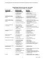
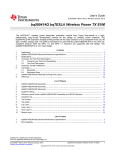
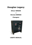
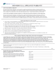
GENERAL LABORATORY
REFRIGERATORS AND FREEZERS
Installation, Operation and
Maintenance Instructions
INSPECTION
When the equipment is received, all items should be carefully checked against the bill of lading to
insure all crates and cartons have been received. All units should be inspected for concealed
damage by uncrating the units immediately. If any damage is found, it should be reported to the
carrier at once, and a claim should be filed with the carrier. This equipment has been inspected and
tested in the manufacturing facility and has been crated in accordance with transportation rules and
guidelines. Manufacturer is not responsible for freight loss or damage.
INSTALLATION
GENERAL
After the unit crate and crate base have been removed, locate the casters or legs found inside the
cabinet. Attach the casters or legs to the unit base by screwing them into the same threaded fittings
that were used to secure the crate base to the cabinet. Insure that the legs or casters are screwed
completely into the base.
If for some reason the doors are not squared up on the cabinet, the doors can be adjusted. Opening
the door(s) and loosening the screws that hold both the top and bottom hinges to the cabinet can
accomplish this. After adjusting the door so that it is aligned correctly, tighten the screws to securely
hold the hinges in place.
VAPORIZER INSTALLATION
The General Laboratory forced air models require the installation of the condensate vaporizer,
which is shipped inside the unit compartment. The vaporizer should be mounted to the cabinet
bottom. Reference View 1. In lieu of the vaporizer, these units can be plumbed to a floor drain
following local plumbing codes. The cold wall units do not use a vaporizer. Customer installation
is not required.
1
4/06 119503
Note: Disconnect
installation.
power
prior
to
1. Connect the power cord to the vaporizer
and place it in the vaporizer bracket.
2. Attach the vaporizer bracket to the back
of the unit using the four screws as
shown, making sure the plastic drain
tube is in the vaporizer pan.
QuickTime™ and a
Photo - JPEG decompressor
are needed to see this picture.
LOCATION
The refrigeration system located at the top of
the cabinet requires free air access for
proper operation. Allow a minimum four-inch
clearance on the top, rear, and sides of the
cabinet. The cabinet should also be leveled
when it is placed in its permanent location.
View 1
ELECTRICAL
Check the proposed outlet to be used to insure that the voltage, phase, and current carrying
capacity of the circuit from the electrical panel correspond to the requirements of the cabinet. Never
use an extension cord to wire any unit. On permanently connected units, those not furnished with a
plug-in service cord, all inter-wiring between the electrical panel and the unit must be done in
accordance with the National Electric Code and all state and local codes. Refer to the serial tag for
all pertinent electrical information.
Observe all Warning Labels. Disconnect power supply to eliminate injury from electrical
shock or moving parts when servicing equipment.
GENERAL OPERATION
FORCED AIR UNITS
The General Laboratory forced air cabinets employ a unit cooler evaporator located inside the
cabinet as the heat-removing source. Through the refrigeration process, heat is captured in the
evaporator, transferred to the condensing unit on top of the cabinet, and expelled to the surrounding
outside air. It is extremely important to allow a four-inch clearance on the top, rear, and sides of the
unit for the refrigeration process to function properly.
Cold control adjustment
To increase or decrease the internal cabinet temperature, rotate the cold control, located on the unit
cooler, to the desired temperature.
2
4/06 119503
Refrigerators
During the operation of refrigerator units, frost will periodically form on the coil surface. Each time
the compressor cycles "off", the evaporator fans will continue to run, which will keep the internal
temperature uniform and at the same time remove any frost build up on the coil. The water
produced will collect in the unit cooler drain pan and travel down the drain tube to the condensate
vaporizer.
Freezers
After shutting the door on freezer models, a short
amount of time must be allowed before the door
can be reopened. This is due to the tight seal
maintained between the door and the cabinet.
Waiting a few moments for the pressure to equalize
permits the door to be opened easily.
A positive defrost is required to remove frost from
the coil in freezer models. This is accomplished by
energizing heaters during the defrost cycle that are
QuickTime™ and a
positioned on the coil surface. The time clock is
Photo - JPEG decompressor
factory set to allow four defrosts per day. Note:
are needed to see this picture.
Adjustment of the correct time of day will be
required to maintain these defrost periods.
As the preset defrost time is reached, the time clock
automatically terminates the refrigeration process
by turning off the condensing unit and unit cooler
fan motors, and energizes the defrost heaters. As
the coil temperature increases, the frost begins to
melt producing water that runs down the coil to the
unit cooler drain pan and exits through the drain
tube to the vaporizer. After all the frost has been
removed and the coil temperature reaches
approximately 50°F, the defrost is terminated through the action of the defrost termination control
located on the unit cooler, and the refrigeration process resumes. In order to insure that any excess
water remaining on the coil is not sprayed into the cabinet interior, and all heat generated by the
defrost is removed, the unit cooler fans will not operate until the
coil1 temperature reaches
Figure
approximately 25°F.
Time clock adjustments (Freezers)
Setting the correct time of day: To set the correct time of day simply rotate the small inner dial
counterclockwise until the correct time of day on the large dial is opposite the "time" indicator. In
referring to Figure 1, the correct time of day shown is 7:30 a.m.
Number of defrosts per day: The timer is factory set to defrost the evaporator four times a day. If
more defrosts are required, remove a knurled slotted screw from the holder, insert the screw into
the time slot on the large dial where a defrost is desired, and tighten. Insure that an equal time
exists between each defrost pin.
Defrost length adjustment: On the small, upper dial there is a pointer that is used to set a 100%
fail-safe feature. The fail-safe of the timer, refer to Figure 1, is factory set at 30 minutes. With this
feature, the defrost will terminate if a system malfunction occurs during defrost. No adjustment of
this device should ever be necessary. Lengthening the fail-safe time will not lengthen the
defrost cycle.
3
4/06 119503
Figure 1 shows the time switch set to defrost at 2:00 a.m., 8:00 a.m., 2:00 p.m., and at 8:00 p.m.
The fail-safe pointer indicates that the system will revert to cooling thirty minutes after a normal
defrost cycle began should a malfunction occur. WARNING: The fail-safe feature is a safety
mechanism and should never be used to control the length of the defrost period. This feature is
provided to protect the contents of the freezer from damage should the system fail to revert to the
cooling cycle because of mechanical difficulties.
Note: The time switch shown in the illustration is factory set to provide four defrosts per day. This
setting should provide adequate defrosting for even the most heavily used system. If experience
shows that the four set defrost periods are more than necessary, one or more of the knurled
setscrews may be removed. AT LEAST ONE OF THE KNURLED SET SCREWS MUST BE
LOCATED ON THE LARGE LOWER DIAL AT ALL TIMES.
COLD WALL UNITS
The cold wall models employ evaporator tubing embedded in the sidewalls, back, and top of the
unit. During the refrigeration process, heat is removed through the evaporator tubing and expelled
through the condensing unit. Because of the cold wall design, it will be necessary to occasionally
manually defrost the freezer models. To do this, unplug the unit and open the door. Wipe the
cabinet dry when defrosting is complete. With cold wall refrigerators, condensation may form on the
interior of the cabinet and should be periodically wiped dry.
Cold Control Adjustment
The temperature control knob is located on the top of the cabinet behind the facade. To make a
small increase or decrease in the internal cabinet temperature, rotate the control knob as needed.
Enzyme Freezer Only
The Enzyme Freezer is equipped with a programmable controller to control the settings. The
controller, which is located on the facade of the unit, is factory set. Please see the separate
instructions that are included on the operation of this controller.
GENERAL MAINTENANCE
PERIODIC CLEANING
Beginning with the initial installation, the interior surfaces of the cabinet should be periodically
wiped down with a solution of warm water and baking soda. This solution will remove any odors
from spillage that has occurred. The exterior of the cabinet should also be cleaned frequently with a
commercial grade of glass cleaner. Caution: Never use an abrasive or alkaline solution to clean
these units. Wipe dry after cleaning.
Important: Monthly cleaning of the condenser coil located on top of the cabinet should be done.
This cleaning will aid the heat transfer characteristics of the refrigeration system and increase its
efficiency. Dust, dirt, and lint will tend to accumulate on the fins of the condensing unit. This
obstruction will affect the flow of air through the condenser, thereby lowering the efficiency of the
system. A wire brush or a brush with stiff bristles can be used to loosen these particles that are
attached to the fins so that they may be removed with a vacuum cleaner. Failure to keep the
condenser coil clean and clear of obstructions could result in temperature loss and damage
to the compressor.
4
4/06 119503
All moving parts have been permanently lubricated and will generally require no maintenance.
MAINTENANCE SERVICE AND ANALYSIS GUIDE
REFRIGERATION SYSTEMS - ALL MODELS
MALFUNCTION
POSSIBLE CAUSE
SOLUTION
Compressor will not start no hum
1.
2.
3.
4.
5.
Service cord unplugged
Fuse blown or removed
Overload tripped
Control stuck open
Wiring incorrect
1.
2.
3.
4.
5.
Plug in service cord
Replace fuse
Determine reasons and correct
Repair or replace
Check wiring against the diagram
Compressor will not start hums but trips on overload
protector
1.
2.
3.
4.
Improperly wired
Low voltage to unit
Starting capacitor defective
Relay failing to close
1.
2.
3.
4.
Check wiring against the diagram
Determine reason and correct
Determine reason and replace
Determine reason, correct or replace
Compressor starts and runs,
but short cycles on overload
protector
1. Low voltage to unit
2. Overload defective
3. Excessive head pressure
4. Compressor hot-return gas hot
Compressor operates long
or continuously
Short of refrigerant
Control contact stuck
Evaporator coil iced
Restriction in refrigeration
system
5. Dirty condenser
1.
2.
3.
4.
Compressor runs fine, but
short cycles
1.
2.
3.
4.
5.
1.
2.
3.
4.
5.
Starting capacitor open,
shorted or blown
1. Relay contacts stuck
2. Low voltage to unit
3. Improper relay
1. Clean contacts or replace relay
2. Determine reason and correct
3. Replace
Relay defective or burned out
1. Incorrect relay
2. Voltage too high or too low
1. Check and replace
2. Determine reason and correct
Refrigerated space too warm
1.
2.
3.
4.
5.
6.
1.
2.
3.
4.
5.
6.
Standard temperature system
freezes the product
1. Control setting is too low
2. Control points stuck
1. Reset the control
2. Replace the control
Objectionable noise
1.
2.
3.
4.
5.
1.
2.
3.
4.
5.
Pan Area
1.
2.
3.
4.
1. Determine reason and correct
2. Check current, replace overload protector
3. Check ventilation or restriction in
refrigeration system
4. Check refrigerant charge, fix leak if
necessary
Overload protector
Cold control
Overcharge
Air in system
Undercharge
Control setting too high
Refrigerant overcharge
Dirty condenser
Evaporator coil iced
Not operating
Air flow to condenser or
evaporator blocked
Fan blade hitting fan shroud
Tubing rattle
Vibrating fan blade
Condenser fan motor rattles
General vibration
Fix leak, add refrigerant
Repair or replace
Determine cause, defrost manually
Determine location and remove restriction
5. Clean condenser
Check wiring diagram
Differential too close - widen
Reduce charge
Purge and recharge
Fix leak, add refrigerant
Reset control
Purge refrigerant
Clean condenser
Determine reason and defrost
Determine reason, replace if necessary
Remove obstruction for free air flow
6. Worn fan motor bearings
Reform or cut away small section of shroud
Locate and reform
Replace fan blade
Check motor bracket mounting, tighten
Compressor suspension bolts not loosened
on applicable models - loosen them
6. Replace fan motor
1. No cooling
2. Too cold
1. Make sure switch is in the "on" position
2. Adjust temperature control - see instructions
5
4/06 119503
under pan area
3. Adjust temperature control - see instructions
under pan area
3. Too warm
6
4/06 119503