1
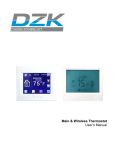
Pioneer Z100 Smart Thermostat
Operating and
Installation Manual
AW000515-B
Page 2
Operating and Installation Manual
Congratulations on the purchase of your new thermostat. It has been designed for easy
programming to save on energy costs and allow a comfortable living environment.
Features:
•
•
•
•
•
•
•
•
•
•
Auto programming mode for your yearly heating and cooling needs
Easy adjustment of temperature and schedule
Energy efficient presets to help reduce heating and cooling costs
Wirelessly communicates with your utility
Notifies you and automatically responds to utility demand response events
Provides you with the current price of energy or rate tier
Lets you select from a range of comfort and savings levels when energy prices increase
Large, easy to read backlit display
Silent operation
Protection against short circuits during installation
Page 3
Table of Contents
OPERATING THE THERMOSTAT ....................................................................................... 7 Navigating the Controls ......................................................................................................... 7 Home Screen ......................................................................................................................... 8 HELP button ........................................................................................................................ 10 Title Bar ............................................................................................................................... 10 Setting the Date & Time....................................................................................................... 11 Default Schedule ................................................................................................................. 12 Temporary Hold ................................................................................................................... 13 Heating and Cooling Modes ................................................................................................ 15 Fan Modes ........................................................................................................................... 15 Temperature Settings .......................................................................................................... 16 Schedule .............................................................................................................................. 17 Extended Holds - Permanent, Timed, and Vacation Holds ................................................. 18 Energy / Price Events .......................................................................................................... 20 Energy Event ....................................................................................................................... 20 Voluntary Energy Event ................................................................................................... 21 Mandatory Energy Event.................................................................................................. 22 Price Conservation Event .................................................................................................... 22 Page 4
Energy Options Screen........................................................................................................ 23 Conservation Screen ........................................................................................................... 24 Temporary Savings SETPOINT........................................................................................... 26 Indicators of Energy Events and Savings ............................................................................ 26 Utility Text Messages........................................................................................................... 27 Temperature Units and Calibration ...................................................................................... 28 Service Information .............................................................................................................. 28 User Options ........................................................................................................................ 29 Languages ....................................................................................................................... 29 Schedule .......................................................................................................................... 29 Change Filter Reminder ................................................................................................... 30 Power Outages .................................................................................................................... 30 INSTALLATION AND MAINTENANCE .............................................................................. 31 Mounting the Thermostat ..................................................................................................... 31 Mounting the Outdoor Sensor.............................................................................................. 31 Cleaning the Thermostat ..................................................................................................... 31 Removing Thermostat Front Housing from Backplate ......................................................... 32 Replacing the Battery .......................................................................................................... 33 Wiring Configuration ............................................................................................................ 34 Setup Menu Options ............................................................................................................ 35 Page 5
Password ......................................................................................................................... 35 Setpoint Range ................................................................................................................ 36 Equipment Type ............................................................................................................... 36 Equipment Settings .......................................................................................................... 37 Conventional Systems .................................................................................................. 37 Heat Pump Systems ..................................................................................................... 38 Control Options ................................................................................................................ 39 Device Info Screen ........................................................................................................... 40 Link Info Screen ............................................................................................................... 41 Reset Screen ................................................................................................................... 43 Thermostat Reset ......................................................................................................... 44 User Configuration Reset ............................................................................................. 46 Reset Security Key ....................................................................................................... 46 Conventional System Test ................................................................................................... 47 Heat-Pump System Test...................................................................................................... 48 Product Conformity .............................................................................................................. 49 Caution ................................................................................................................................ 49 Note: .................................................................................................................................... 50 Page 6
OPERATING THE THERMOSTAT
Navigating the Controls
The function of the LEFT and RIGHT TAB buttons appears on the bottom of the display screen.
Use the SCROLL (▲ ▼) buttons to adjust the temperature, move through the menus options, and
change highlighted values. Press the MENU / SELECT (√) button to access the menu as well as to
select or accept highlighted menu items.
Page 7
Home Screen
The Home screen displays current temperature and operation data. When the Home screen is in
Idle mode, the backlight is on with low brightness. Please note that icons such as heat or fan are
animated when the equipment is running.
Note: A SETPOINT (e.g., LEAVE) is identified by a name and specifies both heating and
cooling target temperatures. See the Temperature Settings section for additional information.
Page 8
By just pressing any of the buttons, the Home screen becomes Active, the backlight brightens and
the MODE and FAN tabs are shown
Pressing the LEFT TAB button changes the thermostat mode (COOL/HEAT/AUTO/EMERG/OFF).
The available options for the thermostat mode will depend on the type of heating or cooling
equipment at your home. Pressing the RIGHT TAB button changes the fan mode (ON/AUTO.
Pressing the SCROLL (▲ ▼) buttons makes the temperatures of the SETPOINTs higher (warmer)
or lower (cooler). You can accept the changes by pressing the LEFT TAB, which will be displaying
ACCEPT, or you can walk away after making the changes. They will be automatically accepted
when the screen goes to the Idle mode (i.e. the backlight diminishes to low).
To see the different menu items displayed, the MENU / SELECT (√) button needs to be pressed
once when the screen is active or twice when it is in the Idle mode.
Page 9
HELP button
The thermostat’s HELP ? button provides you with information on how to navigate through the
individual menu screens. It will help you to quickly change settings without referring to this user
manual; however, it does not replace this manual so please keep this manual for future reference.
Title Bar
The left hand side of the Title Bar displays an icon showing the communications link status and
signal quality.
means Link OFF,
means Link ON, and varies from lowest signal quality (1 bar) to
highest signal quality (5 bars).
The Title Bar also displays the current electricity rate if your utility company provides price
information over the communication link. The price is displayed either in $ value/KWH (default) or
by the price tier name. This is assigned by your utility to different rates (e.g. normal, low, medium,
high, critical peak). By pressing the MENU / SELECT button and selecting the Energy Options
menu item, you can choose which of the two ways the current price is displayed.
Page 10
Setting the Date & Time
When the communications link is active, the network periodically updates the date and time and
you will be prevented from modifying this setting. If the communications link is off, you can set the
current date and time by selecting TIME from the Main Menu. You can always change between a
12H or 24H clock format.
Press the MENU / SELECT button to view the Main Menu as
shown in this screen.
Use the SCROLL buttons to scroll to the TIME menu item.
Press the MENU / SELECT button again to enter the TIME menu.
To change between 12 and 24 hour clock formats, scroll to the
CLOCK FORMAT menu item. Press MENU / SELECT to enter the
CLOCK FORMAT menu item. The setting will be underlined. You
can change the format using the SCROLL buttons and then
pressing SAVE CHANGES to accept the change.
To adjust the date and time, use the SCROLL buttons to scroll to
the ADJUST DATE/TIME menu item. Press MENU / SELECT to
enter the ADJUST DAY/TIME menu.
Press MENU / SELECT to move between fields. Use the SCROLL
buttons to change the value of the underlined field. Press MENU /
SELECT to move between hour and minute adjustment. Press
SAVE CHANGES to accept the new settings and return to the
TIME menu.
Page 11
Default Schedule
The thermostat’s schedule is factory programmed with energy efficient values for START TIMES
and SETPOINTS (listed below).
Note: A SETPOINT has a pre-set name and specifies both heating and cooling target
temperatures, as explained in detail in the Temperature Settings section.
This default schedule may be modified as desired to meet your comfort and schedule requirements.
The thermostat anticipates the time required to reach a desired temperature prior to the start of the
SETPOINT time; therefore, you only need to set the desired time for the SETPOINT temperature.
SCHEDULE
Mon. to Fri.
START
TIMES
Sat. & Sun.
SETPOINT
NAME
HEAT
6:00 am
Wake
70°F (21°C) 78°F (26°C)
8:00 am
Leave
62°F (17°C) 85°F (29°C)
6:00 pm
Return
70°F (21°C) 78°F (26°C)
10:00 pm Sleep
Page 12
COOL
62°F (17°C) 82°F (28°C)
START
TIMES
SETPOINT
NAME
HEAT
Wake
70°F (21°C) 78°F (26°C)
11:00 pm Sleep
62°F (17°C) 82°F (28°C)
8:00 am
COOL
Temporary Hold
A Temporary Hold allows you to temporarily make the temperature warmer or cooler without
affecting the pre-set programming. The thermostat will remain at the Temporary Hold temperature
until the next scheduled SETPOINT.
From the Home screen, press either of the SCROLL buttons to
adjust either the HEAT (if the current operating mode is HEAT) or
the COOL (if the current operating mode is COOL) of the active
target SETPOINT, shown below the room temperature, with two
arrows beside it.
To accept the adjusted SETPOINT, press the LEFT TAB .To
cancel, press the RIGHT TAB. Note that even if you don’t press
the ACCEPT TAB, the Temporary Hold will take effect when the
screen goes on idle (i.e. the screen backlight diminishes to low).
When the thermostat mode setting is AUTO, pressing the MENU /
SELECT button will switch between the HEAT and COOL
SETPOINTS (i.e. the screen will show “ADJUST HEAT” or
“ADJUST COOL” respectively). The LEFT TAB accepts the
Temporary Hold settings and the RIGHT TAB cancels them.
Page 13
Temporary Hold (continued)
Once the Temporary Hold is in effect, the SETPOINT name will be
replaced by TEMPORARY.
To cancel a Temporary Hold, press the SCROLL button to return
to this screen.
Press the RIGHT TAB to cancel the HOLD, or LEFT TAB to
accept it (continue the hold) and return to the normal Home
screen.
Page 14
Heating and Cooling Modes
The thermostat is pre-set for heating operation (HEAT) but, as explained when describing the
HOME SCREEN, you can manually (by pressing the LEFT TAB) change the thermostat mode
between AUTO, HEAT, COOL, OFF, and EMERG.
The available options for the thermostat mode will depend on the type of heating or cooling
equipment at your home.
AUTO:
HEAT:
COOL:
OFF:
EMERG:
The thermostat automatically selects heating or cooling based on the indoor
temperature.
The thermostat controls only the heating system.
The thermostat controls only the cooling system.
Heating and cooling systems are off.
This setting only applies to heat pumps with auxiliary heat. The thermostat only
controls the Emergency (Auxiliary) heat leaving the heat pump’s compressor
locked out. Use this setting only when you suspect the heat pump is out of service
or the outdoor conditions are inefficient for the operation of the heat pump.
Fan Modes
You can manually change the fan mode between AUTO and ON, by pressing the RIGHT TAB.
AUTO:
ON:
The fan runs only when the heating, cooling, or emergency systems are on. For
conventional systems, with the option FAN ON IN HEAT set to NO, the fan is not
controlled by the thermostat but by the furnace. Configuration of the FAN ON IN
HEAT setting is described in the Installation section of this manual.
The fan runs continuously.
Page 15
Temperature Settings
A SETPOINT is identified by a NAME and specifies heating and cooling target temperatures.
Example: If the SETPOINT is set to WAKE, with COOL temperature of 78°F and HEAT temperature
of 70°F, a thermostat operating in AUTO mode will keep your dwelling’s temperature at the
predefined HEAT or COOL temperature. In the summer, the thermostat will COOL your dwelling
down to 78°F. In the fall, the thermostat will engage the HEAT mode, heating your dwelling up to
70°F throughout the winter. In the spring, when temperatures rise again, the thermostat will change
back to COOL mode.
The SETPOINTs HEAT and COOL temperatures can be changed using the SETPOINTS menu.
Choose SETPOINTS from the Main Menu to view this screen.
To change the HEAT and COOL temperature settings, SCROLL
to the SETPOINT you want to change and press the MENU /
SELECT button. SCROLL to change the temperature, or press
again the MENU / SELECT button to move between the HEAT
and COOL settings.
Press the LEFT TAB to SAVE temperature changes.
You can also modify the name of the WAKE, LEAVE, RETURN,
and SLEEP SETPOINTS but not UNOCCUPIED and
OCCUPIED. SCROLL to the SETPOINT you want to change
and press EDIT NAME. You can change one letter at a time by
SCROLLING through the alphabet until you get to the desired
letter, then pressing MENU / SELECT to move to the next letter
of the name. Once done, press SAVE CHANGES.
Page 16
Schedule
The SCHEDULE determines when a SETPOINT such as WAKE begins. Only the start times are
defined; the SETPOINT ends at the start of the next SETPOINT. To delete a start time, SCROLL to
the start time, and select NOT USED as the SETPOINT.
Choose SCHEDULE from the main MENU to view the Schedule
screen. The PROGRAM window displays the SETPOINT associated
with the start time on the right. Adjust the start time by pressing the
MENU / SELECT button and SCROLLING through the time.
Press MENU / SELECT to move inside the PROGRAM window.
Here the SETPOINT can be SCROLLED to choose the name of a
different SETPOINT. Press the MENU / SELECT button again to
return to the start times on the right.
You can have up to 6 scheduled start times. To add a start time,
SCROLL to a blank row, SELECT it, and change the start time.
Change the name NOT USED to an appropriate SETPOINT after
you have added the start time.
Page 17
Extended Holds - Permanent, Timed, and Vacation Holds
The SCHEDULE can be modified to maintain a desired SETPOINT through either a:
•
Permanent Hold (hold until cancelled)
•
Timed Hold (hold for 1 to 99 hours or 1 to 99 days)
•
Vacation Hold (hold until a set date)
Choose EXTENDED HOLD from the main Menu, then select the HOLD TYPE, press MENU /
SELECT, then SCROLL to the desired HOLD TYPE and press MENU / SELECT again.
Permanent Hold
Using the arrow keys, change the HOLD TYPE to PERMANENT
and press the MENU / SELECT key. SCROLL to the line above
HOLD TYPE and press the MENU / SELECT key again, scroll to
choose the desired SETPOINT NAME.
Press SAVE CHANGES to accept the new settings and initiate the
Hold.
To cancel the Hold, return to the EXTENDED HOLD menu and
press the CANCEL HOLD tab.
Page 18
Extended Holds - Permanent, Timed, and Vacation Holds (continued)
Timed Hold
In TIMED hold, choose between 1 and 99 (in hours or days). You
can also choose the SETPOINT to hold.
Press SAVE CHANGES to accept the new settings and initiate the
Hold.
To cancel the Hold, return to the EXTENDED HOLD menu and
press CANCEL HOLD.
Vacation Hold
Choose the HOLD UNTIL date in VACATION hold. You can also
choose the SETPOINT to hold.
Press SAVE CHANGES to accept the new settings and initiate the
Hold.
To cancel the Hold, return to the EXTENDED HOLD menu and
press CANCEL.
Page 19
Energy / Price Events
Energy / Price Events are specific time intervals when your utility institutes higher energy prices, or
when your utility needs to reduce the load on the electricity grid. These events are referred to as:
•
Energy Events
•
Price Conservation Events
Energy Event
During an Energy Event, your utility sends a signal to the thermostat to indicate that the target
SETPOINT temperatures should be modified in order to reduce the energy use by your heating
and/or air conditioning systems.
In the Home screen the SETPOINT name is replaced by the name
of the Energy Event, which is ENERGY EVENT by default.
For each event, your utility will specify when the event will start and end, as well as either a desired
temperature or offset. An offset is the number of degrees above (in COOL mode) or below (in
HEAT mode) the current temperature setting programmed into the thermostat. The event can also
end if your utility cancels it.
An Energy Event can be voluntary or mandatory.
Page 20
Voluntary Energy Event
In the case of a Voluntary Energy Event you may accept the modifications suggested by your utility,
or you can either Override the event or Opt-Out of it.
Overriding a Voluntary Energy Event: You can override an Energy Event while the event is in
progress by choosing SETPOINT values that result in higher energy consumption than the values
specified by the event. This is done from the Home Screen by pushing the up or down arrow
buttons just as you would when setting a Temporary Hold.
When an event is overridden, the SETPOINT values selected
during the Override operation will be applied as if it were a
Temporary Hold. The Home screen will display TEMPORARY,
under the current room temperature.
This Override condition will end when the event ends or a new
event starts.
Opting Out from a Voluntary Energy Event: You can Opt-Out from Voluntary Energy Events by
selecting the Energy Options menu from the Main menu selecting Opt-Out. If you change your
mind, you can Opt-In by selecting Opt-In from the Energy Options menu. Note that once you select
to Opt-Out you will be excluded from all future voluntary energy events until you select to Opt-In
again.
Page 21
Mandatory Energy Event
When an Energy Event is in effect, there is no indication if the
event is mandatory or voluntary. You will know that the event is
mandatory if you try to push the arrow buttons in the direction of
higher energy consumption (i.e. the direction of override). When
this happens during a Mandatory Energy Event, the thermostat
will show this message.
Price Conservation Event
Some utilities have prices which vary depending on the time of day and in some cases when
demand is approaching its highest levels a critical peak price. In these situations your utility can
send Price Information Events. The current price of energy can also be used to trigger a Price
Conservation Event.
When a Price Conservation Event is triggered the thermostat responds based on which of the five
levels you selected from on the Conservation Screen (see Conservation Screen section). Price
Conservation Events are always voluntary and you will be able to override the event by specifying
SETPOINT values requiring higher energy consumption. You can also OPT OUT of Price
Conservation Events.
Note that it is possible to have a new Energy Event while there is still another one happening (e.g.
your thermostat can be under a Price Conservation Event when a Energy Event is being sent by
your utility). In this case, you can decide to override one or both events.
Page 22
Energy Options Screen
The Energy Options screen allows you to disable Voluntary Energy Events and to select which type
of price information you want to be displayed.
Choose ENERGY OPTIONS from the main MENU to view this
screen.
•
ENERGY EVENTS: enables or disables Voluntary Energy
Events. The options are: OPT-IN and OPT-OUT. To change
from OPT-IN to OPT-OUT, you need to press MENU /
SELECT when the arrow is pointing ENERGY EVENT. OPTIN will be underlined. SCROLL to OPT-OUT and press SAVE
CHANGES.
•
PRICE DISPLAY: Defines which type of price information will
be displayed in the Title Bar on the Home screen when there
is a Price Information Event in effect; the options are:
COST/KWH and TIER NAME.
Please note that not all utilities provide price information over the communications link so you may
not see the price information displayed in the Title bar.
Page 23
Conservation Screen
The Conservation Screen allows you to choose your desired comfort level (i.e. from maximum
comfort and no savings to maximum savings and minimum comfort). Please note that not all utilities
provide price information over the communications link so this screen may not be activated for your
program. To use the Conservation Screen, you need to access the Main Menu then press the
MENU / SELECT button when the cursor is on the COMFORT menu item. This takes you to the
Conservation Screen, where you can see the following:
Once on the Conservation Screen, you can choose the level of
Comfort by pressing the arrow (SCROLL) buttons. If you choose
the Maximum Comfort, as shown at the left, your program
settings will not be affected by an increase in price (i.e., you are
prepared to pay the increased rates to maintain your desired
comfort level).
By continuing to press the arrow buttons, you can also choose
Comfort, as it is shown on the left. In this setting the thermostat
adjusts the temperature settings such that there is little or no
adjustments when the price goes up by a small amount but when
rates go higher so do the adjustments; however, this setting
favors comfort over saving.
By choosing the Balanced Level, price increases and
temperature adjustments strike a balance between comfort and
savings.
Page 24
Conservation Screen (continued)
The Savings Comfort Level places a higher value on savings
over comfort such that the temperature adjustments are greater
for a given price increase.
Maximum Savings means that your thermostat will change the
temperature in the direction of maximum energy savings every
time there is an increase in the price of energy.
Page 25
Temporary Savings SETPOINT
When either an Energy or a Price Conservation Event is in effect, you can always choose to modify
the SETPOINTS in the direction of lower energy consumption. These modified values are called
Temporary Savings SETPOINTS, they are always allowed when you enter them (even in the case
of a Mandatory Energy Event). They are displayed the same way as a Temporary Hold.
The Temporary Savings SETPOINTs end either when the event ends or when the next scheduled
SETPOINTs start.
Indicators of Energy Events and Savings
The Thermostat has four Light Emitting Diodes (LEDs) located on the right side of the case, below
the LCD screen. These four LEDs are: RED, ORANGE, YELLOW and BLUE
RED
ORANGE
YELLOW
BLUE
As the price of energy increases, one of the YELLOW, ORANGE or RED LEDs will
light up. The RED LED is used when the price is very high.
This LED will light up when an energy event or a price conservation event is in
progress.
Note that you will see one or, a maximum of two lights on at the same time (i.e., BLUE and one of
the YELLOW, ORANGE or RED lights).
Page 26
Utility Text Messages
Your utility may send text messages to your thermostat to provide information. For example, they
might inform you of upcoming events.
A text message sent from your utility will be displayed when the
thermostat is on the home screen. It will remain displayed until you
acknowledge the message, until the message expires, or until your
utility cancels the message.
To view the last message transmitted by your utility, SCROLL down
in the main menu to GET LAST MESSAGE. Press MENU /
SELECT.
Press OK to confirm that you do wish to retrieve the last message
or press CANCEL to return to the Home screen. If you confirm that
you wish to retrieve the last message, a request will be sent to your
utility, which will send the last text message if applicable.
Page 27
Temperature Units and Calibration
The display can be set to display Fahrenheit (°F) or Celsius (°C) units. Also if you measure the
temperature yourself and believe the thermostat’s displayed temperature is off slightly you can
easily calibrate the thermostat’s display by up to +/- 5.4°F (+/- 3°C) by following these steps.
SELECT TEMPERATURE from the Main Menu.
Change the UNITS by pressing MENU / SELECT on the UNITS
line, then SCROLL between FAHRENHEIT (°F) and CELSIUS
(°C).
To calibrate the thermostat, select the OFFSET line. Press MENU /
SELECT, then SCROLL to change the offset.
Press SAVE CHANGES to accept the new settings, then press
EXIT to return to the main menu.
Service Information
Information regarding your service contractor can be programmed into the thermostat for future
reference.
Choose SERVICE from the main Menu.
Press EDIT NAME and enter the name and contact information
using the MENU / SELECT button to navigate to each letter
position and the SCROLL buttons to change each letter.
After pressing SAVE CHANGES scroll to the next line if you need
to enter additional information; then follow the procedure just
described.
Page 28
User Options
Languages
The thermostat can be set to English or Spanish through the USER OPTIONS screen.
To change from ENGLISH to SPANISH, SCROLL to the USER
OPTIONS on the Main Menu.
Press MENU / SELECT on the LANGUAGE line. SCROLL to the
ESPAÑOL choice (underlined).
Press SAVE CHANGES to save.
Schedule
There are three choices for the weekly schedule:
5/2 DAYS
7 DAYS
5/1/1 DAYS
Mon. – Fri. schedule is the same. Sat. & Sun. schedule is the same
Every day of the week has an individual schedule.
Mon. – Fri. schedule is the same. Sat. has an individual schedule, and Sun. has an
individual schedule.
To change between the three scheduling options, SELECT the SCHEDULE line in the USER
OPTIONS screen, and SCROLL between the different choices.
Page 29
Change Filter Reminder
A CHANGE FILTER reminder may also be set in the USER OPTIONS menu. It can be set from 0
to 12 months. Setting it to 0 months effectively disables the CHANGE FILTER reminder.
After the CHANGE FILTER reminder is enabled, the value shown by this screen will decrease each
month. When it reaches 0, the CHANGE FILTER reminder alarm appears. You can clear the alarm
by touching CLEAR ALARM. In order to re-enable the CHANGE FILTER reminder, set the desired
period and touch SAVE CHANGES.
Power Outages
In the event of a power failure, the thermostat will retain information for proper operation of the
heating and cooling equipment as well as maintaining the time. It will not display information on the
display screen during the power outage. Once the power is restored, the thermostat will continue
operation maintaining all previously stored settings.
Page 30
INSTALLATION AND MAINTENANCE
Mounting the Thermostat
Install the thermostat at 5 feet (1.5m) above the floor in an area with good air circulation at average
temperature. Avoid locations with drafts or dead spots behind doors, hot or cold air ducts, sunlight
or radiant heat from appliances, concealed pipes or chimneys and unconditioned areas such as
outside walls behind the thermostat.
The 2 wallplate anchors should be spaced 3.5 inches (90 mm) apart in a vertical direction. Pull
wires through the backplate and connect to the appropriate terminals as defined in the Wiring
Configuration.
Mounting the Outdoor Sensor
The outdoor sensor should be mounted in a shaded location, out of direct sunlight. The thermostat
will automatically detect the outdoor sensor and display its readings.
Cleaning the Thermostat
The thermostat can be cleaned with a soft cloth lightly dampened with isopropyl alcohol (IPA).
Excessive IPA or use of other solvents may damage the LCD!
Page 31
Removing Thermostat Front Housing from Backplate
To remove the thermostat front housing from the backplate, press the plastic tab located at the
bottom of the thermostat. Pull the bottom of the front housing forward and remove.
Warning: do not use metallic tools when removing battery or backplate; this may damage the
thermostat.
Page 32
Replacing the Battery
A LOW BATTERY WARNING will appear when the battery falls below 10% of its rated capacity.
This procedure does not lose the thermostat settings; however, time settings will require reprogramming if communications are not restored. Replace with a CR-2032 battery.
Many government agencies promote and have battery recycling programs. Contact your local
jurisdictional government agency regarding available recycling programs.
In order to find if there is a suitable recycling facility near your location, please go to:
http://earth911.com/hazardous/single-use-batteries/lithium-manganese-batteries/
In order to be informed about the local regulations for disposing the used battery as a waste, please
go to:
http://www.epa.gov/epawaste/wyl/stateprograms.htm
The battery in the thermostat may contain perchlorate material - special handling may apply.
For more information go to:
www.dtsc.ca.gov/hazardouswaste/perchlorate
Page 33
Wiring Configuration
The thermostat should be wired by a licensed technician familiar with HVAC installation.
Conventional Systems (CONV)
1
Common(GND) C 8
2
Power (24VAC) R 9
3 RS OUT Outdoor Sensor
1st Stage Heat W1 10
4 RS GND Sensor Ground
Fan G 11
5 FILTER Filter
1st Stage Cool Y1 12
6
2nd Stage Cool Y2 13
7
2nd Stage Heat W2 14
1
2
3
4
5
6
7
Page 34
Heat Pump Systems (HP)
Common (GND) C
FAULT Heat Pump Fault
Power (24VAC) R
RS OUT Outdoor Sensor
Auxiliary Heat E
RS GND Sensor Ground
Fan G
FILTER Filter
1st Stage Heat Pump Y1
2nd Stage Heat Pump Y2
Changeover Valve O/B
8
9
10
11
12
13
14
Setup Menu Options
WARNING: Changing settings in the SETUP can damage the HVAC system and should only be
done by a qualified HVAC technician.
Password
Two levels of password protection are programmed in the thermostat: USER and INSTALLER. Both
password levels will timeout after 20 minutes of the last button press and force you to re-enter a
password.
The default INSTALLER password is INST. The INSTALLER password limits access to critical
thermostat settings which include:
•
Password
•
Equipment Settings
•
Setpoint Range
•
Control
•
Equipment Type
•
Reset
The passwords can be changed in the PASSWORD menu.
SCROLL to change either USER or INSTALLER password.
SCROLL through the letters to change the password, or use the
blank letter to set the password to a blank.
Page 35
Setpoint Range
The SETPOINT RANGE sub menu defines the Maximum and Minimum temperatures allowed in
the HEAT and COOL modes. Adjusting these temperatures limits the temperature ranges allowed
when setting SETPOINT temperatures.
Equipment Type
WARNING: The thermostat must be configured correctly to match the equipment type. The number
of cooling and heating stages must be defined in the Conventional or Heat Pump setting.
EQUIPMENT TYPE
CONVENTIONAL
HEAT PUMP
# OF COOL STAGES
# OF HEAT STAGES
# OF COOL STAGES
# OF HEAT STAGES
REV. VALVE
DEFAULT
1
1
1
1
ON IN COOL
OPTION
0-2
0-2
1-2
1-3*
ON IN HEAT
*For Heat Pumps, defining one more heat stage than cool stage(s) indicates that Emergency Heat
(Auxiliary Heat) is installed.
Page 36
Equipment Settings
Conventional Systems
You must enter an Installer Password to access the EQUIPMENT SETTINGS from the Main Menu.
The following settings can be changed for Conventional Systems:
MIN ON/OFF TIME
FAN ON IN HEAT
(this option only
applies to the furnace)
DEFAULT
OPTION
3 MIN
1-6 MIN
Minimum cycle time for the furnace/air conditioner.
YES
NO
The fan turns on when the
The furnace waits until enough
thermostat sends the fan on
heat is built up before turning on
signal. If the Fan Mode is AUTO
the plenum fan. The furnace
the thermostat will turn the fan
controls the fan when the Fan
on whenever the furnace is
Mode is AUTO.
turned on.
Page 37
Heat Pump Systems
You must enter an Installer Password to access the EQUIPMENT SETTINGS from the Main Menu.
The following settings can be changed for Heat Pump Systems:
MIN ON/OFF TIME
ALLOW HP+AUX ON
BALANCE POINTS
Page 38
DEFAULT
OPTION
3 MIN
1-6 MIN
Minimum cycle time for the heat pump/auxiliary heater.
YES
NO
Does not allow Heat Pump and
Allows the Heat Pump and
Auxiliary Heat to be on at the same
Auxiliary Heat to be on at the
time (add-on configuration).
same time.
-38 – 122°F
HIGH
122°F (50°C)
(-39 – 50°C)
The High Balance Point defines the outdoor temperature above which
the Auxiliary Heater is disabled.
-40 – 120°F
LOW
-40°F (-40°C)
(-40 – 49°C)
The Low Balance Point defines the outdoor temperature below which
the Heat Pump compressor is disabled.
An outdoor temperature sensor must be installed for the Balance
Points to operate.
Control Options
You must enter an Installer Password to access the CONTROL menu from the Main Menu. The
following settings can be changed:
DEFAULT
CHANGE
HYSTERESIS
ANTICIPATION TIME
MAX RECOVERY
TIME
OPTION
0-6°F
(0-3°C)
Defines the number of degrees the temperature must go beyond a
setpoint prior to changing from HEAT to COOL mode or vice versa in
AUTO mode.
60 MIN
0 – 180 MIN
The time limit the thermostat is allowed to engage the equipment to
reach a desired temperature. The algorithm determines the time
required to reach the temperature, and engages the equipment prior to
the next Scheduled Setpoint in order to reach the desired temperature
at the appropriate time. The temperature may not be reached if the
ANTICIPATION TIME is less than the time required to heat (or cool) to
the desired temperature.
2°F (1°C)
90 MIN
0 – 180 MIN
The maximum time the thermostat allows the equipment to reach a
ST
desired temperature in 1 stage heating (or cooling). If the thermostat
determines that the desired temperature will not be reached, it will
engage the second (or further) stage of heating (or cooling).
Page 39
Device Info Screen
The Device Info screen is a read-only screen that is available through the Setup menu. The
Installer password must be entered to access the screen.
This screen provides the following information:
• Operating Software (OS): this is a number that identifies the name and version of the
Thermostat Firmware.
• Hardware Version (HW): the Thermostat Hardware Version Major and Minor, are represented
by numbers from 0 to 255, separated by a dot.
• Software Version (SW): the Thermostat Firmware Version Major, Minor and Build, are
represented by numbers from 0 to 255, separated by dots.
• Inside the RADIO box, information related to the Radio Module is provided:
• Radio Module Hardware Version (HW): Major and Minor, are represented by numbers from 0 to
255, separated by a dot.
• Radio Module Software Version (SW): the Radio Module Firmware Version Major,
Minor and Build, are represented by numbers from 0 to 255, separated by dots.
Page 40
Link Info Screen
The Link Info screen is also read-only and is accessed by pressing the LINK INFO soft key in the
Device Info Screen.
The Link Info screen provides the following information:
• The Link Icon, as described in the Title Bar section of this manual.
• RSSI: Received Signal Strength Indicator, which is the signal applied at radio receiver input,
expressed in dBm. The values range is from -30 (very strong signal) to -90 (weak signal).
• Values outside that range should only be used as a relative approximate indication.
• LQI: Link Quality Indicator. A relative indication of the quality of the digitally decoded received
signal, from 0 to 255. A higher number indicates a higher digital link quality (lower packet error
ratio).
• CH: (Channel). The radio channel used.
Page 41
Link Info Screen (continued)
• STATUS: The label inside the box describes the status of the communication link
Possible labels are:
SEARCHING FOR RADIO
SEARCHING FOR NETWORK
JOINING NETWORK
SEARCHING FOR TRUST CENTER
WAITING FOR SECURE LINK
SEARCHING FOR ESP
WAITING FOR VALID CONNECTION
CONNECTION ACTIVE
At the right end of the title bar of the LINK STATUS box is the Status Code. For additional
information about the Status Code please consult your utility.
Other information provided:
MAC: IEEE 802.15.4 EUI Media Access Control address.
IC: Installation Code, which identifies the device. Your utility must know the MAC address and the
Installation Code of a thermostat in order to be able to communicate with it. Typically, your utility
will know these items before a thermostat is connected for the first time. If your utility does not
have this information, or problems are encountered during connection, the installer can read the
MAC address and Installation Code from the Link Info screen and inform your utility.
Pressing the DEVICE INFO tab at the Link Info screen takes you back to the Device Info screen.
Pressing the EXIT tab in either the Device Info screen or the Link Info screen takes you back to the
Setup Menu.
Page 42
Reset Screen
The Thermostat has three different resets to Factory Default values:
• Thermostat Reset
• User Configuration Reset
• Reset Security Keys
The following sections provide additional information on each of these resets.
Page 43
Thermostat Reset
A THERMOSTAT RESET restores the thermostat to the following original manufacturer settings
SETPOINTS
SCHEDULE
COMFORT SETTING
HEAT
COOL
WAKE
70ºF
78ºF
LEAVE
62ºF
85ºF
RETURN
70ºF
78ºF
SLEEP
62ºF
82ºF
UNOCCUPIED
62ºF
85ºF
OCCUPIED
70ºF
78ºF
SETPOINT 7
62ºF
85ºF
SETPOINT 8
62ºF
85ºF
Energy Efficient Schedule (explained previously in Default Schedule section)
MAX COMFORT
ENERGY EVENTS
ENERGY OPTIONS
PRICE DISPLAY
ADJUST DATE/TIME
TIME
CLOCK FORMAT
LANGUAGE
USER OPTIONS
Page 44
CHANGE FILTER REMINDER
OPT-IN
COST/KWH
JAN 1 2000 12:00 AM
12 H
ENGLISH
0 MONTH(S)
Thermostat Reset (continued)
TEMPERATURE
UNITS
FAHRENHEIT (ºF)
USER
[1234] OFF
PASSWORD
INSTALLER
MAX
MIN
SETPOINT RANGE
HEAT
93ºF
41ºF
COOL
EQUIPMENT TYPE
CONVENTIONAL
95ºF
# OF COOL STAGES
# OF HEAT STAGES
3 MIN
YES
2ºF
60 (MINUTES)
90 (MINUTES)
HEAT
AUTO
43ºF
1
1
EQUIPMENT SETTINGS
CONTROL
MODE
MIN ON/OFF TIME
FAN ON IN HEAT
CHANGE HYSTERESIS
ANTICIPATION
MAX RECOVERY TIME
OPERATING
FAN
[INST]
Page 45
User Configuration Reset
The User Configuration Reset will only restore the following settings to the factory default values
listed in the previous Thermostat Reset section:
•
•
•
SETPOINTS
SCHEDULE
COMFORT SETTING
•
•
•
CLOCK FORMAT
LANGUAGE
TEMPERATURE UNITS
Reset Security Key
The thermostat ships from the factory with an initial security key that allows the thermostat to set an
initial temporary connection with the utility. This connection is used so that the thermostat and the
utility can set a permanent secured connection that replaces the initial security key. If this
permanent secured connection fails, it may become necessary for both the thermostat and the
utility to start again from the initial security key to set a new permanent connection
The Reset Security Key operation is performed locally at the thermostat after entering the Installer
Password. This operation resets the link status to factory defaults by clearing the pre-shared link
key, causing a join operation to be activated.
Page 46
Conventional System Test
This procedure allows the installer to bypass delays associated with the minimum on/off times.
OUTPUT TESTED
Fan
1ST stage cooling
2ND stage cooling*
1ST stage heating
2ND stage heating**
PROCEDURE
Mode = Off
Fan = change from AUTO to ON
Mode = COOL
Lower the setpoint by - 5°F (-3°C) from
room temperature and press ACCEPT to
engage HOLD
Remain in COOL mode
Return to Hold function and press
ACCEPT again
Change mode to HEAT, rise the setpoint
by +5°F (+3°C) and press ACCEPT
Remain in HEAT mode, return to Hold
function and press ACCEPT
EXPECTED RESULT
Fan should turn on
First stage cooling should
engage
Second stage cooling
should engage
First stage heating should
engage
Second stage heating
should engage
* Only in two stage cooling systems.
** Only in two stage heating systems.
Page 47
Heat-Pump System Test
This procedure allows the installer to bypass delays associated with the minimum on/off times.
OUTPUT TESTED
PROCEDURE
EXPECTED RESULT
Mode = Off
Fan should turn on
Fan
Fan = change from AUTO to ON
1
ST
stage cooling
2
ND
stage cooling*
1
ST
stage heating
2
ND
stage heating**
Heating using
Auxiliary Heat**
Mode = COOL
Set the setpoint by at least -5°F (-3°C)
below room temperature and press
ACCEPT to engage HOLD
Remain in COOL mode
Return to the Hold function and press
ACCEPT again
Mode = HEAT
Set the setpoint by at least +5°F
(+3°C) above room temperature and
press ACCEPT
Remain in HEAT mode
Return to the Hold function and press
ACCEPT again
Remain in HEAT mode
Return to the Hold function and press
ACCEPT again
* Only in two stage heat pump systems.
** Only with Heat-Pump systems equipped with an Auxiliary Heater.
Page 48
First stage cooling should
engage
Second stage cooling should
engage
First stage heating should
engage
Second stage heating should
engage.
Auxiliary heating should
engage (if there are more heat
stages then cool stages)
Product Conformity
This equipment is RoHS compliant.
This equipment, if installed in strict accordance with the manufacturer’s instructions, complies with
the limits pursuant to Part 15 of FCC rules.
Operation is subject to the following two conditions:
1. This device may not cause harmful interference
2. This device must accept any interference, including interference that may cause undesired
operation.
Contains Radio Module FCC ID: WUR-ZRM10; Industry Canada ID: 8022A-ZRM10
Caution
You are cautioned that any changes or modifications not expressly approved by Energate, Inc.
could void your authority to operate this equipment.
Page 49
Note:
This equipment has been tested and found to comply with the limits for a Class B digital device,
pursuant to part 15 of the FCC Rules. These limits are designed to provide reasonable protection
against harmful interference in a residential installation. This equipment generates, uses and can
radiate radio frequency energy and, if not installed and used in accordance with the instructions,
may cause harmful interference to radio communications. However, there is no guarantee that
interference will not occur in a particular installation. If this equipment does cause harmful
interference to radio or television reception, which can be determined by turning the equipment off
and on, the user is encouraged to try to correct the interference by one or more of the following
measures:
• Reorient or relocate the receiving antenna.
• Increase the separation between the equipment and receiver.
• Connect the equipment into an outlet on a circuit different from that to which the receiver is
connected.
• Consult the dealer or an experienced radio/TV technician for help.
Page 50
Page 51
© All Rights Reserved
Page 52