1
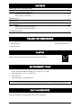
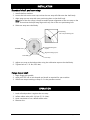
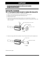
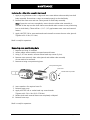
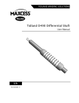
TIDLAND WINDING SOLUTIONS Tidland XPCP Commonality Shaft User Manual EN MI 593373 1 G CONTENTS IMPORTANT SAFETY INSTRUCTIONS 3 ASSEMBLY DIAGRAM AND PARTS LIST 4 Standard shaft assembly........................................................................................... 4 Flange mount assembly ............................................................................................ 4 INSTALLATION 5 OPERATION 5 MAINTENANCE 6 Replacing rubber tube assembly ............................................................................... 6 Replacing core positioning bars ............................................................................... 7 TROUBLESHOOTING 8 TIDLAND CUSTOMER SERVICE 1.360.834.2345 www.maxcessintl.com 1.800.426.1000 CAUTION Wear eye protection when using tools and compressed air. RECOMMENDED TOOLS Clean, non-lubricated air supply: 80-100 psi (5.5-6.9 bar) Hex wrenches: 3/16", 1/4" and 5/16" LOCTITE 243® Dow Corning 55 o-ring lubricant For more accessories to help with your winding processes, visit www.maxcessintl.com DAILY MAINTENANCE Use compressed air to keep shaft free of dust and debris. www.maxcessintl.com Tidland XPCP Commonality Shaft MI 593373 1 G Page 2 of 8 IMPORTANT SAFETY INSTRUCTIONS When using this Tidland product, basic safety precautions should always be followed to reduce the risk of personal injury. Your company's safety instructions and procedures should always be followed. When using this product with any other equipment or machinery, all safety requirements stipulated by that equipment or machinery manufacturer must be followed. Compliance with local, state, and federal safety requirements is your responsibility. No part of these or the following instructions should be construed as conflicting with or nullifying the instructions from other sources. Be familiar with the hazards and safety requirements in your work environment and always work safely. Read and understand all instructions and shaft design application limits before operation. Never use this product for a purpose or in a machine that it was not specifically designed for. See Product Safety Data Sheet (PSDS). Do not exceed the operation loads for this shaft as noted on its PSDS, Product Safety Data Sheet. Follow all warnings and instructions marked on the product and on the PSDS. Do not use fingers or other objects to deflate the shaft; Tidland recommends using the Tidland Air Release Tool (see page Error! Bookmark not defined.). Inspect the shaft for wear and/or other safety and functional deficiencies daily, before each use. Wear safety glasses or proper eye protection when inflating or deflating or otherwise operating the air system. Do not remove or otherwise alter any setscrews or fastening devices prior to using this product. Do not operate this product if any setscrews or fastening devices are missing. Do not lift shaft manually if it is beyond your capacity. Loads over 1/3 your body weight may be prohibitive. Consult your company safety policy. When lifting a shaft, use proper lifting techniques, keeping back straight and lifting with the legs. Do not carry or lift this product over wet or slippery surfaces. Use appropriate mechanical lifting devices, such as a hoist or shaft puller, for heavier shafts. When performing maintenance or repair procedures, do not pressurize the shaft if journal setscrews are loose or missing. When performing maintenance procedures, do not pressurize the shaft if the journal is missing. All replacement parts used on this product should be made to original Tidland specifications. All maintenance and repair procedures performed on this product should be done to Tidland specifications by qualified personnel. If shafts with rubber air systems are stored longer than two weeks - store them completely deflated, away from electric motors, away from direct sunlight or florescent light, and in temperatures not exceeding 85ºF (29ºC). When storing shafts with constant air pressure, the rubber air systems are subject to distortion or cold flow. www.maxcessintl.com Tidland XPCP Commonality Shaft MI 593373 1 G Page 3 of 8 ASSEMBLY DIAGRAM AND PARTS LIST Standard shaft assembly 1 2 3 4 5 6 7 Item 1 2 3 4 5 6 7 Description Qty Shaft body Core positioning bars Rubber tube assembly Non-valve journal Nose cone Socket head cap screws Core Stop Assembly includes threaded insert and Soc hd cap Scr 3/8-24NF x 1 3/4" LG 1 4 1 1 1 2 1 1 1 With the use of interchangeable core positioning bar sets, the 06.88 XP CP Leaf Shaft accommodates four core ID sizes. Call Tidland Customer Service for part numbers or more information. 1-800-426-1000 Flange mount assembly Spindle Mounting flanges Core stop www.maxcessintl.com Shaft assembly Tidland XPCP Commonality Shaft MI 593373 1 G Page 4 of 8 INSTALLATION Standard shaft and core stop 1. Install shaft on machine. 2. Loosen the bolt on the core stop so that the core stop will slide onto the shaft body. 3. Align tangs on core stop with core positioning bars on the shaft body. Note: One of the four tangs is keyed to enable proper alignment of the core stop on the shaft. Ensure that the keyed tang aligns with any one of the core positioning bars. 4. Slide core stop onto shaft body. Keyed tang over core positioning bar Bolt Core positioning bar (4 plcs) Threaded insert Alignment tang (4 plcs) Shaft body Core stop 5. Adjust core stop to desired position using the calibration tape on the shaft body. 6. Tighten bolt to 15 ft·lbs (20.3 Nm). Flange mount shaft 1. Align flange with spindle. 2. Apply LOCTITE 243 to bolt threads and install as required for your machine. 3. Install core stop according to Steps 2-6 in the previous section. OPERATION 1. Load roll and position it against the core stop. 2. Inflate rubber tube to 80–100 psi (5.5-6.9 bar). 3. Upon completion of run, deflate rubber tube. 4. Remove core. www.maxcessintl.com Tidland XPCP Commonality Shaft MI 593373 1 G Page 5 of 8 MAINTENANCE All maintenance can be performed while shaft is mounted in machine. Use appropriate safety precautions. Replacing rubber tube assembly Note: It is not necessary to remove core stop when replacing rubber tube assembly. 1. Ensure that rubber tube assembly is completely deflated. 2. Using 1/4" hex wrench, loosen non-valve journal set screws (2 plcs). 3. Remove the socket head cap screws from the nose cone. 4. Remove the nose cone. 5. Unscrew the non-valve journal from the body. Use a strap wrench, if necessary. Older shaft models do not have threaded journals: journals can be pulled off after nose cone is removed. Non-valve journal set screw (2 plcs) Non-valve journal Nose cone Soc hd cpscr (2 plcs) 6. Remove existing rubber tube assembly. Grasp firmly by hand and pull completely out. O-rings (2 plcs) Rubber tube assembly (Continued next page) www.maxcessintl.com Tidland XPCP Commonality Shaft MI 593373 1 G Page 6 of 8 MAINTENANCE Replacing the rubber tube assembly (continued) 1. Apply o-ring lubricant to the o-rings and insert new rubber tube assembly into shaft body assembly. Ensure that o-rings are seated properly in the shaft body. 2. Reinstall the nose cone and non-valve journal in shaft body assembly. Note: If parts do not insert completely, ensure that the rubber tube assembly is inserted all the way into the shaft. Nose cone should make contact at core positioning bars or shaft body. (There will be a 1/16"-1/8" gap between nose cone and external leaves.) 3. Apply LOCTITE 243 to setscrew threads and reinstall to secure the non-valve journal. Tighten to 20 ft·lbs (27.1 Nm). Shaft is ready for operation. Replacing core positioning bars 1. Remove core stop, if installed. 2. Inflate rubber tube assembly to expand external leaves. 3. Using 5/16" hex wrench, remove socket head cap screws (2 plcs). 4. Remove nose cone only. Non-valve journal and rubber tube assembly do not need to be removed. 5. Remove existing core positioning bars. Core positioning bars Nose cone Socket head cap screws 6. Insert new bars for required core I.D. 7. Reinstall nose cone. 8. Apply LOCTITE 243 to socket head cap screw threads. Tighten to 40-50 in·lbs (54.2-67.8 Nm). 9. Deflate shaft until external leaves are completely collapsed. 10. Reinstall core stop. Shaft is ready for operation. www.maxcessintl.com Tidland XPCP Commonality Shaft MI 593373 1 G Page 7 of 8 TROUBLESHOOTING Problem Possible cause Recommended solution Nose cone doesn't seat Rubber tube assembly Remove nose cone/non-valve is not properly seated journal sub-assembly and inside the shaft. ensure that rubber tube is inserted properly. O-rings should be lubricated with Dow Corning 55 o-ring lube. Nose cone loose Loose non-valve Ensure nose cone and non-valve journal set screws journal are correctly positioned in the shaft body. Apply LOCTITE 243 to set screw threads and tighten to 20 ft·lbs (27.1 Nm). Core stop moves Core stop installation Tighten core stop bolt to bolt loose 15 ft·lbs (20.3 Nm). Core positioning bars Rubber tube assembly Inflate rubber tube assembly difficult to insert deflated completely. Core doesn't fit onto shaft Nose cone size too Replace nose cone with correct large size. Core positioning bars Replace positioning bars with too large correct size. Core bumps against ends of Nose cone size too Replace nose cone with correct core positioning bars when small size. Roll slipping during Rubber tube assembly Inflate rubber tube assembly to operation not properly inflated 80–100 psi (5.5-6.9 bar). loading. NORTH, CENTRAL AND SOUTH AMERICA EUROPE, MIDDLE EAST AND AFRICA CHINA Tel +1.360.834.2345 Fax +1.360.834.5865 [email protected] www.maxcessintl.com Tel +49.6195.7002.0 Fax +49.6195.7002.933 [email protected] www.maxcess.eu Tel +86.756.881.9398 Fax +86.756.881.9393 [email protected] www.maxcessintl.com.cn INDIA JAPAN KOREA, TAIWAN, AND SE ASIA Tel +91.22.27602633 Fax +91.22.27602634 [email protected] www.maxcess.in Tel +81.43.421.1622 Fax +81.43.421.2895 [email protected] www.maxcess.jp Tel +65.9620.3883 Fax +65.6235.4818 [email protected] © 2013 Maxcess www.maxcessintl.com Tidland XPCP Commonality Shaft MI 593373 1 G Page 8 of 8