1
EXPERIMENT NO. 5:
Amplitude Shift Keying
AIM: To study Amplitude Shift Keying modulation and demodulation.
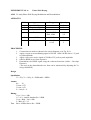
APPARATUS:
SI. No.
Apparatus
1.
2.
3.
4.
IC 741
Transistor SI 100
Diode OA79
Resistors
5.
6.
POT
Capacitor
Range
100 kΩ
22 kΩ
2.2 kΩ
10 kΩ
0.01 uF
Quantity
1
1
1
Each 1
1
1
PROCEDURE:
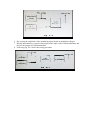
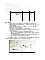
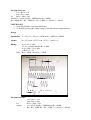
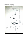
1. Connections are made as shown in the circuit diagrams shown in Fig. P9.1.
2. Apply a square wave modulating signal of 500 Hz (1000 bits/ sec) and 0V peak
to peak amplitude.
3. Apply a sine wave carrier signal of 50 kHz of 5V peak-to-peak amplitude.
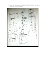
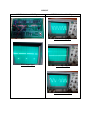
4. Observe ASK waveform at point A.
5. Demodulate the ASK signal using the envelope detector.
{The error in the demodulated wave form can be minimized by adjusting the Vref
using 10 KΩ POT}
6. To find minimum frequency of carrier signal for proper detection.
i. After step No. 5, start reducing the freq2uency of the sine wave carrier signal
from 50 kHz gradually.
ii. At a particular frequency of the carrier signal, the demodulated signal does
not tally with the modulating square wave signal.
The minimum frequency of the carrier sine wave signal is that frequency, when
demodulated signal tally with the modulating signal for the first time.