1
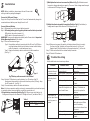
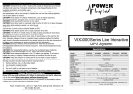
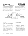
Atom Series Quick Guide
1
V.1.0
Product Introduction
Atom is a compact unit which combines both benefits of UPS and inverter for long-time
operation. With built-in voltage stabilizer, it works as a UPS to accept wide input
voltage range and convert to stable and pure power source to the connected devices.
Besides, it also can provide stable power to a various of electronic devices from
personal computers, energy saving bulbs, television, to small inductive devices
such as fans. It is perfect choice for home owners or small office users in the unstable
power area.
2
CAUTION! The unit is designed for indoor use. Do not expose this unit to rain, snow
or liquids of any type.
CAUTION! To reduce risk of injury, only use qualified batteries from qualified
distributors or manufacturers. Any unqualified batteries may cause damage and
injury. Do NOT use old or overdue batteries. Please check the battery type and date
code before installation to avoid damage and injury.
WARNING! It's very important for system safety and efficient operation to use
appropriate external battery cable. To reduce risk of injury, external battery cables
should be UL certified and rated for 75 C or higher. And Do not use copper cables
less than 10AWG.
Table 1 Minimum Recommended Battery Cable Size versus Length
Atom 600
Typical Amp.
50 A
1 meter (one-way)
AWG 8
Dia-mm
6.0
Product Overview
CAUTION! Do not disassemble the inverter. Contact with the qualified service center
when service or repair is required.
WARNING! Provide ventilation to outdoors from the battery compartment. The
battery enclosure should be designed to prevent accumulation and concentration
of hydrogen gas at the top of the compartment.
CAUTION! Use insulated tools to reduce the chance of short-circuit when installing or
working with the inverter, the batteries, or other equipments attached to this unit.
CAUTION! For battery installation and maintenance, read the battery manufacturer's
installation and maintenance instructions prior to operating.
Back View:
Front View:
1
4
2
3
4
1
3
2
1
2
3
4
Power switch
Line mode indicator: green lighting
Battery mode indicator: yellow flashing
Fault indicator: red lighting
India Type
1
2
3
4
Universal Type
AC input
Output receptacles
Circuit breaker
External battery terminal
4
Specifications
Model
3
Important Safety Warning
( SAVE THESE INSTRUCTIONS)
Personnel Precaution CAUTION! Careful to reduce the risk or dropping a metal tool on the batteries. It could
spark or short circuit the batteries and could cause an explosion.
CAUTION! Remove personal metal items such as rings, bracelets, necklaces, and
watches when working with batteries. Batteries can produce a short circuit current
high enough to make metal melt, and could cause severe burns.
CAUTION! Avoid touching eyes while working near batteries.
CAUTION! Have plenty of fresh water and soap nearby in case battery acid contacts
skin, clothing, or eyes.
CAUTION! NEVER smoke or allow a spark or flame in vicinity of a battery.
CAUTION! If a remote or automatic generator start system is used, disable the
automatic starting circuit or disconnect the generator to prevent accident during
servicing.
CAPACITY
INPUT
Voltage
Voltage Range
Frequency
OUTPUT
Output Voltage (Batt. mode)
Frequency Range (Batt. mode)
Transfer Time
Waveform
BATTERY
Battery Voltage
Maximum Charge Current
PHYSICAL
Dimension (DxWxH mm)
Net Weight (kgs)
ENVIRONMENT
Humidity
Temperature
Atom 600
600 VA / 300 W
230 VAC
140~300 VAC
50 Hz or 60 Hz
± 10%
50 Hz ± 1 Hz or 60 Hz ± 1 Hz
13 ms max.
Simulated Sine Wave
12 VDC
13 A
358.5 X 96.8 X 146.5
5.8
0-90 %
0-40 C (non-condensing)
5
2)Multiple batteries in series connection(Refer to Fig. 3): All batteries must
be equal in voltage and amp hour capacity. The sum of their voltages must be equal
to the nominal DC Voltage of the unit.
Installation
NOTE: Before installation, please inspect the unit. Be sure that
nothing inside the package is damaged.
Connect to Utility and Charge
Plug in the AC input cord to the wall outlet. The unit will automatically charge the
connected external battery even though the unit is off.
Connect External Battery
Step 1- Take away the cover of external battery terminal.
Step 2- Following battery polarity guide printed near the battery terminal!
RED cable to the positive terminal (+);
BLACK cable to the negative terminal (-).
WARNING! Please use the appropriate battery cable. Please refer to Important
Safety Warnings Section for the details.
Step 3- There are two terminal types.
Type 1: Screw battery cables to terminals with the M5 nuts. Do NOT place
anything between the flat part of battery terminal and the battery
cable ring terminal, or overheating may occur.
Type 2: Simply screw battery cables to terminal with flat screwdriver.
(See Fig. 1)
+-
Type 1
Fig.1 Battery cable connects to the terminal
Step 4- Install a DC Breaker in a positive battery line. The rating of the DC
Breaker must be according to the inverter's battery current (50 Amp). Keep
the DC breaker off. (see Fig. 2)
Step 5- Connect battery cables to the external batteries.
Note: For the user operation safety, we strongly recommend that you should use tapes
to isolate the battery terminals before you start to operate the unit.
1)Single battery connection(Refer to Fig. 2): When using a single battery, its
voltage must be equal to the Nominal DC Voltage of the unit (see below Table 1).
+
Table 1
DC
breaker
+ -
Model
Nominal Battery DC Voltage
Atom 600
12VDC
+
-
-
+ -
Fig. 3
3)Multiple batteries in parallel connection(Refer to Fig. 4): Each battery's
voltage must be equal to the Nominal DC Voltage of the unit.
+
+
+
-
-
-
+ -
Fig. 4
Step 6- Make sure to connect the polarity of battery side and the unit correctly.
Positive pole (Red) of battery to the positive terminal (+)of the unit.
Negative pole (Black) of battery to the negative terminal (-) of the unit.
Step 7- Put the covers back to the external battery terminals.
Step 8- Take the DC breaker on.
6
Trouble Shooting
Use the table below to solve minor problems.
Problem
Type 2
+
Utility power is
normal but the unit
is in battery mode.
When power fails,
the backup time is
shorten.
Probable Cause
AC input power cord is not
connected well.
Input breaker is activated.
The unit is overload.
Battery voltage is too low.
Battery capacity is not full
even after charge the unit
for at least 8 hours.
No LED display on
the front panel when
the utility power is
normal.
The unit is not turned on.
Battery is not connected
well.
Fig. 2
Battery defect.
Battery voltage is too low.
Solution
Check AC input power
connection.
Reset the input breaker.
Remove some non-critical
loads.
Charge the unit at least
8 hours.
Check the date code of the
battery. If the batteries
are too old, replace the
batteries.
Press power switch to turn
on the unit.
Check the external battery
cable and terminal. Make
sure all the battery
connections to the unit are
all correct.
Replace the batteries.
Charge the unit at least
8 hours.