1
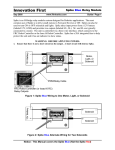
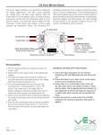
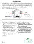
12V Victor 884
IFIROBOTICS
25 Sept 06
Users Manual - Page 1
www.IFIrobotics.com
The Victor speed controllers are specifically engineered
for robotic applications. The high current capacity, low
voltage drop, and peak surge capacity make the Victor
ideal for drive systems while its braking options and
precise control meet the demanding needs of arms and
lift systems. This controller safely handles the high
continuous current draws and extreme current surges
produced by Competition robots. The innovative FET
switching architecture and an integral cooling fan
ensures cool FET junction temperatures. The low
voltage drop and high switching speed ensures the motor
receives maximum power, providing significant
improvements in acceleration, direction changes, and
lifting torque. The LED indicator will be GREEN in
‘full-forward’ condition, RED in ‘full-reverse’ and
ORANGE while in neutral.
Fan GND (BLK)
BLK
M
GND
BLK
TO BATTERY GND
TO MOTOR and
TO MOTOR
30A
BREAKER
TO BATTERY 12V
RED
Fan 12V (RED)
PWM EXTENSION CABLE
TO RECEIVER PWM
M
12
WRB
Innovation First
BC
Brake/Coast Jumper
VICTOR 884
Cal Button
RED
LED Indicator Status
• Green = Full Forward
• Orange = Neutral / Brake
• Red = Full Reverse
• Flashing Orange = no PWM
LED Indicator
Wiring Guidelines
1.
The fan must be wired so it is always ON when the
Victor is ON.
2.
Attach the fan wires and connect to the appropriate
voltage.
the Victor. This will ensure the wires do not move
and loosen the connections.
WARNING: BEFORE APPLYING POWER:
3.
The input and output wires should be 10AWG wire
minimum and firmly connected to ensure low
voltage drop and minimal temperature rise.
1.
Ensure the input connections are not reversed.
Connecting 12V and GND backwards will
destroy the unit.
4.
Use circle lugs designed for your wire size. The lug
should have a hole designed for a #6 or #8 screw. If
the center hole is too large, (#10 or larger)
inadequate mechanical contact may result in
excessively high resistance and temperature rise.
2.
Ensure that there is not a short circuit on the
output. A short circuit will destroy the unit.
3.
Ensure there is a circuit breaker either inline
with the 12V power input to the speed controller,
or inline with the motor. Use an appropriate
circuit breaker for your application to ensure
that long term exposure to a stalled motor (high
currents) will not overheat the Victor.
5.
Check all lug connection after crimping and
soldering. You should not be able to pull the lug off
the wire with your hands.
6.
Once the input and output wires are firmly
connected, tie the wires using tie straps within 2” of
12V Victor 88
IFIROBOTICS
25 Sept 06
Users Manual - Page 2
www.IFIrobotics.com
PWM Connection
You will need (1) PWM extension cable or PWM Signal
Driver.
1. Use a PWM Signal Driver to ensure the signal from
your receiver is Victor compatible if you are not
using an IFI Control System.
2. The male PWM cable connector connects to the
speed controller. The Victor housing is design to
provide a firm connection. Trim the shroud corners
slightly if necessary for insertion into the Victor.
3. The PWM extension cable should be installed with
the black wire towards the fan.
4. Standard Radio Controlled PWM connectors are
fragile. Use caution when inserting and removing
the PWM cable so the contacts on both connectors
are not damaged.
Mounting Guidelines
You will need (2) #4 or #6 screws.
1. The Victor can be installed in any orientation.
2. The speed controller must have adequate space
above the fan for airflow, a minimum of 2 inches.
3. Do not over-tighten the mounting screws through
the speed controller. A snug connection will hold
the speed controller in place without crushing the
case.
Calibration Instructions
The Victor is pre-calibrated to values compatible with an
IFI Control System and re-calibration is not needed.
You can re-calibrate to achieve ‘full forward/reverse’
from your joystick movement if necessary.
NOTE: While in calibration mode, the Victor will
record the max PWM value detected as ‘full forward’,
the min PWM value as ‘full reverse’, and ‘neutral’ will
be the PWM value recorded at the release of the Cal
button. The following steps will guide.
3.
While continuing to hold the Cal button, move the
joystick to the maximum and minimum positions.
This can be done in any order and as many times as
desired.
4. While continuing to hold the Cal button, return the
joystick to center (neutral position).
5. Release the Cal button.
6. A flashing GREEN indicator confirms a successful
calibration.
7. A flashing RED indicator denotes an unsuccessful
calibration.
An unsuccessful calibration occurs when either:
a)
Insufficient joystick travel was detected in forward
and/or reverse.
b) The trim tab is too far from center.
Resetting Calibration to Factory Pre-calibration:
1. Power OFF the speed controller.
2. Press and hold the Cal button.
3. While continuing to hold the Cal button, Power ON
the speed controller.
4. A flashing GREEN indicator denotes calibration is
reset. Release the Cal button.
Brake / Coast Configuration
The Brake / Coast jumper is used to set the speed
controller’s action during a neutral condition. The Brake
provides significant resistance to motor rotation and is
recommended for motors driving linkages and arms that
can be back-driven by gravity or other external forces.
The speed controller checks the status of the jumper
approximately 60 times per second. This allows the user
to change from brake to coast during operation. A limit
switch may be connected to the jumper connector instead
of the jumper. The limit switch can be triggered by
various means including the use of a servo.
Brake / Coast Guidelines: Reference Diagram
1.
User Calibration:
1.
2.
Power ON the speed controller.
Press and hold the Cal button. After a moment, the
LED indicator on the Victor will begin alternating
between RED and GREEN to indicate a cal mode.
2.
3.
The jumper should always be installed. If you lose
the jumper, a standard computer jumper will work.
The Coast condition (Jumper on Inner two Pins) sets
the output to an open circuit during neutral.
The Brake condition (Jumper on Outer two pins)
sets the output to a short across the motor leads
during neutral.
IFIROBOTICS
25 Sept 06
www.IFIrobotics.com
12V Victor 884
Users Manual - Page 3
Troubleshooting
Indication: No ORANGE indicator on power up.
Problem: Input power issue or joystick trim tab off
center.
Possible Solutions:
1. Disconnect PWM cable.
2. If indicator blinks ORANGE, the PWM value that
was being received is either between ‘neutral’ and
‘full forward’, or between ‘neutral’ and ‘full
reverse’. Check joystick trim tab to ensure the
controller is not in a partial forward or a partial
reverse condition. If no change, check that the
joystick and receiver channels match.
3. If indicator remains off, check +V or GND
connections for voltage and proper polarity.
Indication: Flashing ORANGE indicator on power up.
Problem: No PWM signal.
Possible Solutions:
1. Ensure the transmitter and receiver are powered ON.
2. The PWM cable may be improperly connected.
Check wire color-coding at each end. Check that
the connector is not off a pin at the receiver end.
3. Check for a good PWM signal by connecting a
known good servo to the PWM extension cable. If
the servo does not move, this can indicate either:
a) a faulty receiver
b) an improperly connected cable
c) a bad PWM extension cable
Note: The servo requires that 5V be present on the
center pin of the PWM cable. This connection is not
required for the Victor.
Indication: Flashing RED indicator after calibration.
Problem: Calibration Failed.
Possible Solutions:
1. Inadequate travel in forward or reverse. Repeat the
calibration procedure and move the joystick further
forward and/or further reverse.
2. The joystick trim tab is NOT centered. Neutral
cannot be extremely far from center.
Indication: No power output from the speed controller
although the indicator LED works.
Problem: Possible internal damage.
Possible Solutions:
If the indicator on the Victor is operating properly and
there is no output, the Victor may be internally damaged.
This condition is typically caused by a short circuit on
the output or there has been an over-current condition to
caused a failure.
Check the following:
1. Ensure the indicator is changing between ORANGE,
RED and GREEN with joystick movement.
2. Disconnect the motor and check the output (M+ to
M-) with a voltmeter. The meter should read
between + Battery voltage with corresponding full
range joystick movement.
If the indicator is working properly and the outputs are
not working properly, the speed controller is probably
damaged. The final test to determine if the Victor is
damaged is to replace it with another Victor.
Indication: No power output from the speed controller
and the indicator does NOT work.
Problem: No input power or possible internal damage.
Possible Solutions:
If the indicator on the Victor is not operating properly
and there is no output, the Victor may be internally
damaged. This condition is typically caused by no input
power or a reverse polarity on the input.
Check the following:
1. Disconnect the output wires.
2. Ensure the indicator on the Victor will not
illuminate at any joystick position.
3. Check the input at the Victor (+BATTERY to GND)
with a voltmeter.
If the indicator is not working properly and the input is
good, the speed controller is probably damaged. The
final test to determine if the Victor is damaged is to
replace it with another Victor.
CAUTION: Prior to replacing a potentially damaged
speed controller, ensure that the wires connected to
the output are not shorted and the input is not
reversed. Also verify that neither of the motor output
leads are shorted to the chassis of the motor and/or
the robot.
APPENDIX A: Document Version History
Date Code
1-26-05
9-25-06
Changes
Revised Brake/Coast Section
Revised Brake/Coast Section
Page 2