1
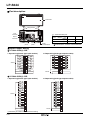
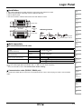
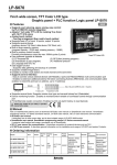
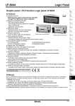
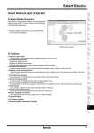
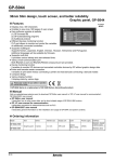
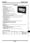
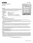
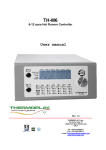
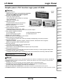
LP-S044
Logic Panel
Graphic panel + PLC function Logic panel LP-S044
(A)
Photo
electric
sensor
Features
(B)
Fiber
optic
sensor
4.4 inch
● Compact structure
MONO
: Reducing cost, space saving and easy operation
through PLC+HMI+Input/ output integration
● Improved compatibility with logic
: 8000-step program capacity
(the average processing speed 6 to 7μs/step)
basic command 28,
application command 220
● Wide device range
: Peripheral device 10K word, data device
10K word, and other various devices
● Sufficient external I/O
[Terminal block connector type]
: Input 16 points, output 16 points(basic)
[Ribbon cable connector type]
● Various expansion function
: External interrupt, 16-key input, 7 Seg.
time-sharing display and synchronous communication output.
● Easy software upgrade at website
(1) LP firmware file (2) GP Editor(drawing program)
(3) Smart Studio(logic program) (4) Additional protocol
● Displays max. 400 characters
● Enables to save max. 500 pages of user screen
● Different devices monitoring function
: PLC port allows to monitor and control the variables of additionally connected controllers
● Supports multilingual
: Supports for Korean, Japanese, English, Chinese, Russian, Vietnamese and Portuguese.
Additional languages will be available by firmware.
● Supports multi-font
: It provides various bitmap and user-selected fonts.
● Various multi-communication ports
: Both RS232 2 port and RS232/RS422 compound port are provided.
● Device monitoring function
: It enables to monitor LP device and connected controller devices by LP without graphic design data.
● Printer and barcode reader connection
: It enables to print alarm history connecting a printer and read barcode connecting a barcode reader.
(C)
Door/Area
sensor
(D)
Proximity
sensor
(E)
Pressure
sensor
(F)
Rotary
encoder
(G)
Connector/
Socket
(H)
Temp.
controller
(I)
SSR/
Power
controller
(J)
Counter
(K)
Timer
(L)
Panel
meter
(M)
Tacho/
Speed/ Pulse
meter
(N)
Display
unit
(O)
Sensor
controller
(P)
Switching
mode power
supply
Please read “Caution for your safety” in operation
manual before using.
(Q)
Stepper
motor&
Driver&Controller
Manual
Visit our webwite(www.autonics.com) to download 'GP Editor user manual' or 'SmartStudio user manual', 'SmartStudio
programing manual', 'LP Series command manual', 'LP-S044 user manual', 'GP, LP user manual for communication'.
● GP Editor user manual
It describes how to write screen data, and is about related usage of LP-S044 HMI function.
● SmartStudio user manual, SmartStudio programming manual, LP Series command manual
It contains install method and usage, commands, etc of SmartStudio.
● GP, LP user manual for communication : It describes connection for external devices such as PLC.
● LP-S044 user manual : It describes general information on the installation and usage of LP-S044 and system contents.
(R)
Graphic/
Logic
panel
(S)
Field
network
device
(T)
Software
(U)
Other
R-21
LP-S044
Ordering information
Model
Item
Series
Monitor Display
Color
size
unit
LP-S044-S1D1-C5T-A
Logic
panel
S
series
Interface
Module
RS232C,
RS422
(1EA
MONO
for each) All-in(blue, 24VDC
one
white)
type
RS232C
(2EA)
LP-S044-S1D0-C5T-A
LP-S044-S1D0-C5R-A
Power
supply
STN
4.4 inch
LCD
LP-S044-S1D1-C5R-A
I/O
Expansion
I/O connector
composition
function type
IN:
16points
OUT:
16points
Terminal block
connector
Ribbon cable
connector
Supports
Terminal block type A
connector
Ribbon cable
connector
Specifications
LP-S044-S1D0-C5T-A
Terminal block connector Ribbon cable connector
Power supply
24VDC
Allowable voltage range
90 to 110% of power supply
Power consumption
Max. 3.6W
Graphic drawing
performance
Display
performance
Model
I/O connector type
LP-S044-S1D0-C5R-A
LP-S044-S1D1-C5T-A
LP-S044-S1D1-C5R-A
Terminal block connector Ribbon cable connector
LCD type
4.4inch STN Blue Negative
Resolution
240×80 dots
Display area
112.8mm×37.6mm
Color
MONO(blue, white)
LCD view angle
Top/Bottom/Left/Right 30° in each direction
Backlight
White LED
Brightness
Adjustable by software
Language※1
English, Korean, Japanese, Chinese, Russian, Vietnamese, Portuguese
Text
• High resolution display up to 400 letters • 6×8, 8×8 ASCII character, high definition numbers
• 8×16 ASCII characters, 16×16 regional characters(1 to 8 times bigger for width, 0.5 to 5 times bigger for height)
Graphic drawing memory 384 KB
Number of user screen
500 pages
Width 15×Height 4 = 60
Command
Basic command : 28, application command : 220
Program capacity
8K step
Processing time
Average : 6 to 7㎲/step
I/O control type
Batch processing
Computer control mode
Repeated-doubling method, interrupt processing
Device range
Serial interface
*Refer to LP-S044 user manual
Each port of RS232C, RS422(asynchronous method) Two ports of RS232C(asynchronous method)
Real-time controller
RTC embedded
Battery life cycle
Approx. 3 years at 25℃
Insulated resistance
Min. 100MΩ(at 500VDC megger)
Ground
3rd grounding(max. 100Ω)
Noise trength
± 0.5kV the square wave noise(pulse width : 1㎲) by the noise simulator
Dielectric strength
500VAC(50/60Hz) for a minute
Control
performance
Touch switch
Vibration
Shock
Environ
-ment
Mechanical
0.75mm amplitude at frequency of 10 to 55Hz(for 1 min.) in each of X, Y, Z directions for 1 hour
Malfunction
0.5mm amplitude at frequency of 10 to 55Hz(for 1 min.) in each of X, Y, Z directions for 10 min.
Mechanical
300m/s²(approx. 30G) in each of X, Y, Z directions for 3 times
Malfunction
100m/s²(approx. 10G) in each of X, Y, Z directions for 3 times
Ambient temperature 0 to 50℃, storage : -20 to 60℃
Ambient humidity
35 to 85% RH, storage : 35 to 85% RH
Protection ratings
IP65F(for front panel)
Accessory
Fixing bracket : 4EA, Rubber waterproof ring, Battery included
Approval
Weight※2
Approx. 454g(approx. 312g)
※1: Language can be customized.
※2: This weight is with packaging and the weight in parentheses is only unit weight.
※Environment resistance is rated at no freezing or condensation.
R-22
Logic Panel
Input/Output performance
Input performance
Input point
Insulation method
Voltage range
Rated input voltage
Rated input current
Input resistance
Response time
Common method
Output performance
Output point
Insulation method
Voltage range
Rated input voltage
Max. load current
Max. voltage falling when ON
Response time
Common method
16 points
Photo coupler insulation
19.2 to 28.8VDC
24VDC
Approx. 4mA
5.6㏀
1ms
16 points/1COM
(A)
Photo
electric
sensor
16 points
Photo coupler insulation
19.2 to 28.8VDC
24VDC
0.1A/1point, 1A/1COM
Max. 0.2VDC
1ms
16 points/1COM
(B)
Fiber
optic
sensor
(C)
Door/Area
sensor
(D)
Proximity
sensor
(E)
Pressure
sensor
Functional description
Line, rectangle, circle, text, bitmap
Displays the designated device as numerical value.(decimal, hexadecimal, octal, binary, real number)
Displays the designated device value as ASCII character.
Displays current time or date.
Registers alarm history.
Displays generated (not backed up) alarm.
Displays the designated comment as device status or value.
Displays lamp as device status.
Displays the designated parts as device status and value.
Displays several device values with a graph of broken line.
Displays change of device value for time with a graph of broken line.
Displays a device value with a bar graph.
Displays a ratio of several device values with pie graph.
Tags
Figure display
Numeral display
ASCII display
Time display
Alarm history
Alarm list
Comment display
Lamp
Part display
Line graph
Trend graph
Bar graph
Statistic graph
Panel meter
(F)
Rotary
encoder
(G)
Connector/
Socket
(H)
Temp.
controller
(I)
SSR/
Power
controller
(J)
Counter
Displays a device value as panel meter.
Touch key
Numeral input
ASCII input
System information function
Recipe function
Security function
Barcode read function
Floating alarm function
Overlap window
Observe status function
(K)
Timer
Screen is switched, word/bit device values are set when it touched.
Configures user input value in device.
Configures user input ASCII code value in device.
Monitors/Controls LP operation from PLC.
Reads/Writes several PLC device collectively.
Only acceptable user can observe/operate important data.
Connects barcode reader, read barcode.
Warning message is floated when alarm is generated.
Specific bit device is ON/OFF for designated day and time.
Available to form dynamically overlapping another base screen on the base one.
(L)
Panel
meter
(M)
Tacho/
Speed/ Pulse
meter
(N)
Display
unit
(O)
Sensor
controller
Dimensions
(unit: mm)
135
● Panel cut-out
Min. 170
Min. 100
66 - 0
+ 0.5
(Q)
Stepper
motor&
Driver&Controller
136
(R)
Graphic/
Logic
panel
+ 0.5
- 0
(S)
Field
network
device
※Panel thickness
: Max. 4mm
(T)
Software
● Fixing bracket
M4 BOLT
12
(U)
Other
9
65
75
50.5
83
4
145
(P)
Switching
mode power
supply
21.7
R-23
LP-S044
Part description
LCD screen
Fixing bracket
Input
connector
※1: Communication port
Output
connector
Model
Communication
port A※1
Communication
port B※1
Power
terminal block
Communication
port
Port A
LP-S044-S1D0-C5T(R)
RS422
RS232C
LP-S044-S1D1-C5T(R)
RS232C-A
RS232C-B
※For more information, refer to R-32 page and
' Serial interface' of GP/LP common features.
Input·Output wiring
LP-S044-S1D0(1)-C5R
● Input wiring(source type input module)
24VDC
X0
X1
X2
X3
X4
X5
X6
X7
COM1
COM3
0
1
2
3
4
5
6
7
+
+
8
9
A
B
C
D
E
F
+
+
X8
X9
XA
XB
XC
XD
XE
XF
COM2
COM4
● Output wiring(sink type output module)
L
L
L
L
L
L
L
L
Y0
Y1
Y2
Y3
Y4
Y5
Y6
Y7
24VDC
0
1
2
3
4
5
6
7
+
+
8
9
A
B
C
D
E
F
+
+
Y8
Y9
YA
YB
YC
YD
YE
YF
L
L
L
L
L
L
L
L
LP-S044-S1D0(1)-C5R
● Input wiring(source type input module)
24VDC
X0
X1
X2
X3
X4
X5
X6
X7
X8
X9
XA
XB
XC
XD
XE
XF
COM1
COM2
0
1
2
3
4
5
6
7
8
9
A
B
C
D
E
F
+
+
※Check the pin number of the case before wiring.
R-24
● Output wiring(sink type output module)
L
L
L
L
L
L
L
L
L
L
L
L
L
L
L
L
24VDC
Port B
Y0
Y1
Y2
Y3
Y4
Y5
Y6
Y7
Y8
Y9
YA
YB
YC
YD
YE
YF
0
1
2
3
4
5
6
7
8
9
A
B
C
D
E
F
+
-
Logic Panel
Installation
(A)
Photo
electric
sensor
1. Set a rubber waterproof ring after placing the ring's joining part under the LP-S044
2. Adhere closely between each edge of the LP-S044 and the rings.
3. Set LP-S044 in panel.
4. Set the fix bracket to 4 bracket slots and fix them with bracket's screws.
(B)
Fiber
optic
sensor
(C)
Door/Area
sensor
(D)
Proximity
sensor
(Upper view)
Rubber
waterproof
ring
Mounting slot
for bracket
(E)
Pressure
sensor
● Mounting bracket
(F)
Rotary
encoder
(Lower view)
(G)
Connector/
Socket
M4 Screw driver
Approx. 0.3N.m
(H)
Temp.
controller
(I)
SSR/
Power
controller
Sold separately
I/O terminal block and I/O cable
Suitable I/O terminal block
INPUT/OUTPUT
AFS-H20
(Interface terminal block)
OUTPUT
ABS-H16PA(TN)-NN
(Relay terminal block)
AFE4-H20-16LF
(Sensor connector terminal block)
-
INPUT
CJ-HPHP20-V1N -1ANR
OUTPUT
CJ-HPHP20-V1N -1APR
INPUT
CJ-HPHP20-V1N -1BNR
OUTPUT
CJ-HPHP20-V1N -1APR
-
(J)
Counter
Suitable I/O cable
(K)
Timer
(L)
Panel
meter
(M)
Tacho/
Speed/ Pulse
meter
CJ-HP20-VP -R(OPEN type cable)
CJ-HP20-VP -L(OPEN type cable)
(N)
Display
unit
※It is only for ribbon cable connector (hirose connector) type.
※" " is for cable length. (Basic specification 010 : 1m, 020 : 2m, the others are option)
※For more information, refer to "I/O terminal block & cable catalog".
(O)
Sensor
controller
Communication cable (RS232C, RS422 port)
(P)
Switching
mode power
supply
For serial connectable cable to connect PLC and external devices, refer to the R-32 page for "GP/LP communication
cable".
(Q)
Stepper
motor&
Driver&Controller
(R)
Graphic/
Logic
panel
(S)
Field
network
device
(T)
Software
(U)
Other
R-25