1
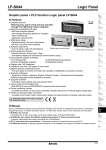
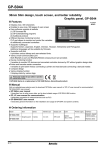
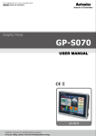
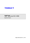
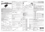
GP-S070
Graphic Panel
7 inch wide screen, TFT Color LCD type
Graphic touch panel GP-S070
Features
NEW
● Adopts 7 inch wide TFT LCD for realizing
True Color with 16,777,216 colors
● Analog touch method
: Free tag arrangement than matrix touch method
● Data logger function
: Supports data gathering and backup of controller
● Supports variable image library
● Enables to monitor multi station and multi channel at
the same time
● Supports several interface
: Supports USB Host/Device to high speed download and
manage files
7 inch TFT Color LCD
: Easy to connect various external devices with RS232C 2 ports
and RS232C/RS422 multi-communication port
● Supports several fonts: Supports window true type and several bitmap fonts (selectable)
● Device monitoring function
: Enables to monitor/control variable of connected control through communication port
● Easy S/W upgrade at website
(1) GP firmware file
(2) GP Editor (drawing program)
(3) Additional protocol
(4) Language and font, etc
● Connects printer/barcode reader: Enables to print out alarm history, to read barcode
(D)
Proximity
sensor
(E)
Pressure
sensor
(F)
Rotary
encoder
(G)
Connector/
Socket
(H)
Temp.
controller
(I)
SSR/
Power
controller
(J)
Counter
(K)
Timer
(L)
Panel
meter
(M)
Tacho/
Speed/ Pulse
meter
Manual
Visit our webwite(www.autonics.com) to download 'GP Editor user manual' or 'GP, LP user manual for communication',
'GP-S070 user manual'.
(N)
Display
unit
● GP Editor user manual
It describes how to write screen data, and is about related usage of GP-S070 HMI function.
(O)
Sensor
controller
● GP, LP user manual for communication
It describes connection for external devices such as PLC.
(P)
Switching
mode power
supply
● GP-S070 user manual
It describes general information on the installation and usage of GP-S070 and system contents.
(Q)
Stepper
motor&
Driver&Controller
Ordering information
GP-S070-T9D6
GP-S070-T9D7
(B)
Fiber
optic
sensor
(C)
Door/Area
sensor
Please read “Caution for your safety” in operation
manual before using.
Model
(A)
Photo
electric
sensor
Item
Series
Monitor size
Display unit
Color
Power supply Interface
Graphic
panel
S series
7 inch
TFT Color
LCD
16,777,216
color
24VDC
RS232C, RS422, USB HOST,
USB DEVICE, Ethernet
RS232C (2EA), USB HOST
USB DEVICE, Ethernet
(R)
Graphic/
Logic
panel
(S)
Field
network
device
(T)
Software
(U)
Other
R-17
GP-S070
Specifications
GP-S070-T9D6
GP-S070-T9D7
24VDC
90 to 110% of power supply
Max. 7.2W
7 inch TFT Color LCD
800×480 dots
152.4mm×94.44mm
16,777,216 color
Within each 50°/ 60°/ 65°/ 65°of top/bottom/left/right
White LED
Adjustable by software
English, Korean
• Vector font
• 6×8, 8×8 ASCII character, high definition numbers
Text
• 8×16 ASCII characters, 16×16 regional characters(1 to 8 times bigger for width, 0.5 to 5 times bigger for height)
Graphic drawing memory 16MB
Number of user screen 500 pages
Touch switch
Analog touch
Asynchronous method: Each port of RS232C, RS422
Serial interface
Each port of RS232C, RS422
Two ports of RS232C
USB interface
Each of USB HOST, USB Device(Version 1.1)
Ethernet interface
IEEE802.3(U), 10/100Base-T
Real-time controller
RTC embedded
Battery life cycle
Approx. 3 years at 25℃
Insulated resistance
Min. 100MΩ(at 500VDC megger)
Ground
3rd grounding(max. 100Ω)
Noise resistance
± 0.5kV the square wave noise(pulse width: 1㎲) by the noise simulator
Withstanding voltage
500VAC 50/60Hz for a minute
Mechnical
0.75mm amplitude at frequency of 10 to 55Hz(for 1 min.) in each of X, Y, Z directions for 1 hour
Vibration
Malfunction
0.5mm amplitude at frequency of 10 to 55Hz(for 1 min.) in each of X, Y, Z directions for 10 min.
Mechanical
300m/s²(approx. 30G) in each of X,Y,Z directions for 3 times
Shock
Malfunction
100m/s²(approx. 10G) in each of X,Y,Z directions for 3 times
Environ Ambient temperature 0 to 50℃, storage: -20 to 60℃
-ment
Ambient humidity
35 to 85% RH, storage: 35 to 85%RH
Protection
IP65F for front panel
Accessory
Fixing bracket: 4EA, Battery(included)
Approval
Unit weight
Approx. 520g
※1: Language can be customized.
※Environment resistance is rated at no freezing or condensation.
Graphic drawing Display performance
performance
Model
Power supply
Allowable voltage range
Power consumption
LCD type
Resolution
Display area
Color
LCD view angle
Backlight
Brightness
Language※1
Functional description
Tags
Figure display
Numeral display
ASCII display
Time display
Alarm history
Alarm list
Comment display
Lamp
Part display
Line graph
Trend graph
Bar graph
Statistic graph
Panel meter
Touch key
Numeral input
ASCII input
System information function
Recipe function
Security function
Barcode read function
Floating alarm function
Time operation
Overlap window
Observe status function
R-18
Line, rectangle, circle, text, bitmap
Displays the designated device as numerical value.(decimal, hexadecimal, octal, binary, real number)
Displays the designated device value as ASCII character.
Displays current time or date.
Registers alarm history.
Displays generated (not backed up) alarm.
Displays the designated comment as device status or value.
Displays lamp as device status.
Displays the designated parts as device status and value.
Displays several device values with a graph of broken line.
Displays change of device value for time with a graph of broken line.
Displays a device value with a bar graph.
Displays a ratio of several device values with pie graph.
Displays a device value as panel meter.
Screen is switched, word/bit device values are set when it touched.
Configures user input value in device.
Configures user input ASCII code value in device.
Monitors/Controls GP operation from PLC.
Reads/Writes several PLC device collectively.
Only acceptable user can observe/operate important data.
Connects barcode reader, read barcode.
Warning message is floated when alarm is generated.
Specific bit device is ON/OFF for designated day and time.
Available to form dynamically overlapping another base screen on the base one.
Changes PLC device status/value of PLC when trigger is generated.
Graphic Panel
Dimensions
(unit : mm)
● Panel cut-out
Min. 240
185
6.5
194
Min. 175
(D)
Proximity
sensor
(E)
Pressure
sensor
28.5
※Panel thickness
: Max. 4mm
(F)
Rotary
encoder
● Fixing bracket
146
125
15
134
(B)
Fiber
optic
sensor
(C)
Door/Area
sensor
126 +1.0
0
186
Max. 4-R3
+1.1
0
(A)
Photo
electric
sensor
(G)
Connector/
Socket
M4 BOLT
(H)
Temp.
controller
(I)
SSR/
Power
controller
(J)
Counter
(K)
Timer
Part description
(L)
Panel
meter
(M)
Tacho/
Speed/ Pulse
meter
(N)
Display
unit
(O)
Sensor
controller
(P)
Switching
mode power
supply
LCD Screen
Fixing bracket
(2 slots is in upper side, 2 slot is in lower side)
RS422
RS422
or
or Ethernet USB
Power terminal RS232C RS232C
Device
-A
-B
block
(Q)
Stepper
motor&
Driver&Controller
USB
Host
(R)
Graphic/
Logic
panel
(S)
Field
network
device
(T)
Software
Mounting slot
for bracket
(U)
Other
● Ethernet Port: For connecting LAN cable and hub, use direct cable, and for connecting PC directly, use cross cable.
● USB Device: It is used to upload and download project (it is required to install USB driver on PC), and when connect
to PC, it can be used as a USB memory (PC recognizes it as a removable disk).
● USB Host: It is used to manage data and upgrade firmware.
● RS232C, RS422 ports: For more information, refer to R-32 page and ' Serial interface' of GP/LP common features.
R-19
GP-S070
Installation
1. Set GP-S070 in panel.
2. Set fixing brackets in 4 slots(2 slots is in upper side, 2 slots is in lower side).
(Upper side)
Mounting slot
for bracket
(Lower side)
3. Tighten fixing bracket with M4 Screw driver and tightening torque is 0.3 to 0.5N·m.
M4 Screw driver
Sold separately
Transmission cables connectable into external devices such as PLC are sold separately. (refer to the R-32 page for "GP/
LP communication cable".)
R-20