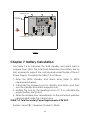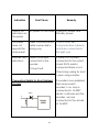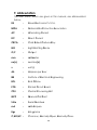
1
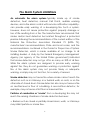
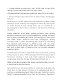
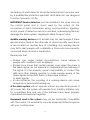
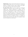
RE–127 Series
Fire Alarm Repeater Panel
Installation, Commissioning & Operating
user Manual
Fire Alarm System Limitations
An automatic fire alarm system–typically made up of smoke
detectors, heat detectors, manual Call Points, audible warning
devices, and a fire alarm control with remote notification capability–
can provide early warning of a developing fire. Such a system,
however, does not assure protection against property damage or
loss of life resulting from a fire. The Manufacturer recommends that
smoke and/or heat detectors be located throughout a protected
premise following the recommendations of the current edition of the
National Fire Protection Association Standard 72 (NFPA 72),
manufacturer's recommendations, State and local codes, and the
recommendations contained in the Guide for Proper Use of System
Smoke Detectors, which is made available at no charge to all
installing dealers. A study by the Federal Emergency Management
Agency (an agency of the United States government) indicated
that smoke detectors may not go off in as many as 35% of all fires.
While fire alarm systems are designed to provide early warning
against fire, they do not guarantee warning or protection against
fire. A fire alarm system may not provide timely or adequate
warning, or simply may not function, for a variety of reasons:
Smoke detectors may not sense fire where smoke cannot reach the
detectors such as in chimneys, in or behind walls, on roofs, or on the
other side of closed doors. Smoke detectors also may not sense a fire
on another level or floor of a building. A second-floor detector, for
example, may not sense a first-floor or basement fire.
Particles of combustion or "smoke" from a developing fire may not
reach the sensing chambers of smoke detectors because:
• Barriers such as closed or partially closed doors, walls, or chimneys
may inhibit particle or smoke flow.
1
• Smoke particles may become "cold," stratify, and not reach the
ceiling or upper walls where detectors are located.
• Smoke particles may be blown away from detectors by air outlets.
• Smoke particles may be drawn into air returns before reaching the
detector.
The amount of "smoke" present may be insufficient to alarm smoke
detectors. Smoke detectors are designed to alarm at various levels
of smoke density. If such density levels are not created by a
developing fire at the location of detectors, the detectors will not go
into alarm.
Smoke detectors, even when working properly, have sensing
limitations. Detectors that have photoelectronic sensing chambers
tend to detect smoldering fires better than flaming fires, which have
little visible smoke. Detectors that have ionizing-type sensing
chambers tend to detect fast-flaming fires better than smoldering
fires. Because fires develop in different ways and are often
unpredictable in their growth, neither type of detector is necessarily
best and a given type of detector may not provide adequate
warning of a fire.
Smoke detectors cannot be expected to provide adequate warning
of fires caused by arson, children playing with matches (especially in
bedrooms), smoking in bed, and violent explosions (caused by
escaping gas, improper storage of flammable materials, etc.).
While a fire alarm system may lower insurance rates, it is not
a substitute for fire insurance!
Heat detectors do not sense particles of combustion and alarm only
when heat on their sensors increases at a predetermined rate or
reaches a predetermined level. Rate-of-rise heat detectors may be
subject to reduced sensitivity over time. For this reason, the rate-of2
rise feature of each detector should be tested at least once per year
by a qualified fire protection specialist. Heat detectors are designed
to protect property, not life.
IMPORTANT! Smoke detectors must be installed in the same room as
the control panel and in rooms used by the system for the
connection of alarm transmission wiring, communications, signaling,
and/or power. If detectors are not so located, a developing fire may
damage the alarm system, crippling its ability to report a fire.
Audible warning devices such as bells may not alert people if these
devices are located on the other side of closed or partly open doors
or are located on another floor of a building. Any warning device
may fail to alert people with a disability or those who have recently
consumed drugs, alcohol or medication.
Please note that:
o Strobes can, under certain circumstances, cause seizures in
people with conditions such as epilepsy.
o Studies have shown that certain people, even when they hear a
fire alarm signal, do not respond or comprehend the meaning of
the signal. It is the property owner's responsibility to conduct fire
drills and other training exercise to make people aware of fire
alarm signals and instruct them on the proper reaction
to alarm signals.
o In rare instances, the sounding of a warning device can cause
temporary or permanent hearing loss.
A fire alarm system will not operate without any electrical power. If
AC power fails, the system will operate from standby batteries only
for a specified time and only if the batteries have been properly
maintained and replaced regularly.
Equipment used in the system may not be technically compatible
with the control. It is essential to use only equipment listed for service
with your control panel.
3
Telephone lines needed to transmit alarm signals from a premise to a
central monitoring station may be out of service or temporarily
disabled. For added protection against telephone line failure,
backup radio transmission systems are recommended.
The most common cause of fire alarm malfunction is inadequate
maintenance. To keep the entire fire alarm system in excellent
working order, ongoing maintenance is required per the
manufacturer's recommendations, and UL and NFPA standards. At a
minimum, the requirements of NFPA 72 shall be followed.
Environments with large amounts of dust, dirt or high air velocity
require more frequent maintenance. A maintenance agreement
should be arranged through the local manufacturer's representative.
Maintenance should be scheduled monthly or as required by
National and/or local fire codes and should be performed by
authorized professional fire alarm installers only. Adequate written
records of all inspections should be kept.
4
NOTES:
5
6
Table of Contents
CHAPTER 1: Introduction ………….......................……....................9
1.1: System Design & Planning............................................9
1.2: General .……….............................................................9
1.3: Fire Alarm Procedure …...............................................10
CHAPTER 2: Product Description ...........................…….................11
2.1: Product Features .........................................................11
2.2: Specifications .........................................................…..12
2.3: Controls and Indicators ................................................14
2.3.1: LED Indication..........................................…………...14
2.3.2: Controls…………………………..….…………………..15
2.4: Mechanical Construction…………………………………16
CHAPTER 3: Installation .............................................……..........….19
3.1: Installation Precaution…………………………………….19
3.2: Mounting Details .................................................….….22
3.3: Input Circuits.............................................................…..23
3.4: Output Circuits .........................................................…..23
3.5: Fire Relay
.........................................................…..24
CHAPTER 4: Programming Instructions ......................……........…24
4.1: Menu Key Flow Diagram...........................................…24
4.1.1: RE-127R / RE-127M……………………………24
4.1.2: RE-127M…………………………………………26
4.2: Programming…………………………….........................28
4.2.1: Suppressed Events………………………………..28
4.2.1.1: Supervisory………………………………..29
4.2.1.2:Fault…………………………………………30
4.2.2:Program………………………………………………30
4.2.2.1: Repeater Setting…………………………..30
4.2.2.1.1: Change Password..………………31
4.2.2.1.1.1: User Password……….….31
4.2.2.1.1.2: Admin Password………...32
7
4.2.2.1.2: Repeater Type…………………….32
4.2.2.1.3: Restore default…………………….33
4.2.2.2: Network Configuration…………………….33
4.2.2.2.1: Zone Config………………………..33
4.2.2.2.2: Location program…………………..34
4.2.2.2.3: Panel select mode………………….35
4.2.2.2.4: View model………………………….35
4.3 About ………………………………………………………….. 36
4.4 Reset…………………………………………………………….36
CHAPTER 5: Operating Instructions...….............……………..….....37
5.1: Switch Functions …………………….............................37
5.2: Status LEDs..................................….........................…38
5.3: Operation..................................................................….39
5.3.1: Normal Monitoring Mode…………………………..39
5.3.2: Fire Alarm Condition…..…………………………...40
5.3.3: Supervisory………………………….......................41
5.3.4: Fault …………………………………………………42
5.3.5: Zone Isolation……………………………………….43
CHAPTER 6: Servicing...….............……………..….....44
CHAPTER 7: Battery Calculation……………………………45
CHAPTER 8: Trouble Shooting……….…….….……………46
CHAPTER 9: Abbreviation……..….……………………….…48
8
Chapter 1: Introduction
This manual is intended as a complete guide to the RE - 127Series
common conventional repeater Panel. User operating Instructions
are provided in the first part of this manual. This is followed with
sections describing installation and commissioning procedures and
full technical details are provided.
1.1 System Design and Planning
It is assumed that the system, of which this repeater panel is a
part, has been designed by a competent fire alarm system designer
in accordance with the requirements of IS 2189: 1988 and any other
local codes of practice that are applicable. The design drawings
should clearly show the positions of the field devices and the control
equipment.
1.2 General
The panel is self-contained with integral power supply and
space provision for two sealed lead-acid standby batteries and
comply with the requirements of IS 2189: 1988. The panel functions
are microprocessor controlled. Provision is made for a repeater
function of panel status output.
Installation
The panel is easy to install and operate. Control functions
Programming functions are enabled by using password. The panel
fascias are retained by tamper-proof screws.
9
1.3 Fire Alarm Procedures
In accordance with IS 2189: 1988, written procedures should be laid
down for dealing with alarms of fire, fault warnings, and the isolation
of any part of the system. The responsible person should ensure that
users of the system are instructed in its proper use and are familiar
with the procedures.
On hearing the fire alarm:
CARRY OUT THE PRESCRIBED PROCEDURE Subsequent actions will
depend on the circumstances, and may include silencing the
audible alarms and resetting the system, as described later.
To Evacuate the premises:
Press the Evacuate key and enter the password to OPERATE
SOUNDERS.
Fault Indication:
If the control panel indicates a Fault condition, make a note of all
illuminated indicators, refer to the chart on page 41, and call the
engineer.
10
Chapter 2: Product Description
RE-127Series consist of conventional Fire alarm repeater Panel &
Gas release panel. The RE-127R & RE-127M is compatible for RE-2558,
RE-2554 and RE-700. It repeats the functions like fire, fault, supervisory
etc that occur on the main panel. The RE-127GR is compatible for
RE-120GR and RE-25AR. The Repeater panel is connected to the
FACP via the RS485 using CAT5E communication cable.
2.1Product Features
Operates on 120 to 220V AC, 60 / 50 Hz.
20 X 4 Characters LCD display.
Repeats all the indication / Information of main panel.
RS 485 Communication for Standalone / Network Repeater.
System ON, AC ON, Battery ON, Charger ON indications.
Alphanumeric keypads.
Sounder (Evacuate) test facility.
Lamp test facility.
RE-127R & RE-127M is Compatible with RE-2558, RE-2554, RE-700.
RE-127GR is compatible with RE-120GR, RE-25AR.
11
Notification
Appliance
circuit
Relay output
for
Fault & Fire
RS-485
Communication
port
RAVEL RE-127-RP-PS
+
CN6
MOV3
Primary Source Input
220V A.C, 50Hz
Q3
F2
MOV1
F1
MOV2
R 39
26Pin FRC
output to
Display board
24VDC input
C18
L2
L1
C17
R4
C6
C12
C16
C3
C9
D2
D3
Stand by source
12V 12Ah Battery
R3 8
R 40
Tx1
R 41
D4
C19
Stand by source
12V 12Ah Battery
Figure -1
2.2 Specification
AC Power:
120 - 220VAC 60/50 Hz
Battery (Lead Acid only)
Charging Current: Constant Voltage – 27.6v @ 0.8A (Max.).
Charging Capacity: 7 Amp Hour Battery.
System Quiescent Current: 50mA
Notification Appliance Circuits (Sounder/Hooter Circuit)
Class – B wiring
Operating Nominal Voltage: 24 VDC
12
Sounder (NACs) output: 0.5A
End-Of-Line Resistor: 4.7K, 1/4watt
RS485 Communication Port
Max. Distance:
1.2 Km Max. [CAT5E or Equivalent]
Remote Outputs
Fire Contact (C,NO,NC) : 220VAC @ 0.5A / 30VDC @ 1A.
13
2.3 Control and Indicators.
M odels:
RE-127M (OR) RE-127R (OR) RE-127GR
REPEATER PANEL
SILENCE
Control Keys
SYSTEM ON
MENU
ENTER
AC ON
BATTERY ON
Common & Power
Indications
CHARGER ON
ABORT
LAMP TEST
1
2
3
ABC
DEF
GHI
4
5
6
JKL
MNO
PQR
7
8
9
STU
VWX
YZ
0
#
EVACUATE
PRE RELEASE
RELEASED
Releasing Circuit Indication
Figure -2
2.3.1 LED Indication
System On – Green
A.C On – Green
Battery On – Green
Charger On – Green
Silenced – Yellow
Supervisory–yellow
Fire – Red
Fault –yellow
Abort – yellow (For RE-127GR only)
Pre Release – yellow (For RE-127GR only)
Released – Red (For RE-127GR only)
RAC Fault – yellow (For RE-127GR only)
14
R E-1 2 7 G R
SILENCED
SUPERVISORY
FIRE
FAULT
RAC FAULT
Common & Power
Indications
Local Buzzer
A piezo buzzer provides separate and distinct sounds for alarm,
trouble and supervisory conditions:
Alarm – steady
Fault – pulse 0.5sec ON and 3 sec OFF
Supervisory – 0.25sec ON and 0.25sec OFF
2.3.2 Controls:
SILENCE: During fire/fault condition, silence is used to silence the
external Sounders connected in repeater panel (NAC) and the
internal buzzer tone is changed from continues tone to toggle tone
in fire condition and also used to silence the internal buzzer toggle
tone in fault condition.
NOTE 1: For RE-127M, silence key is also used to silence main panel
connected in network.
MENU KEY: To enter into the Main Menu in the LCD.
ENTER KEY: To accept the programmed or edited menu, mode or
value in the LCD.
Lamp Test: The all LED’s of the panel can be checked using Lamp
Test key. When the lamp test key is pressed, all the LED will glow
continuously for 4 seconds with continuous buzzer tone.
Evacuate Test: The External Hooters or Sounder (NAC) connected in
RE-127series can be activated without the actual fires by using
evacuate Key. The LCD display shows that Evacuate ON as shown
below. The evacuate can bring back to normal condition by bring
back the key pad enable key to disable position or external sounder
are silenced by using the silence key.
NOTE 2: Evacuate test, for RE-127M
ALPHANUMERIC KEYS:
These keys are used for entering the names etc. and numbers.
15
‘*’ Key is used to go back the previous screen in programming
mode.
‘#’ key is used to change the status of modes.
2.4 Mechanical Construction
The enclosure of the Panel is constructed by 18 gauge
(1.22mm) CRCA sheet with powder-coated finish. The ∅19mm of
knockouts are given for cable entry at the top of the cabinet. The
lockable hinged door is provided to access the inside the cabinet.
The panel also has sufficient space to accommodate 2 Nos. of 12v,
7Ah batteries.
16
ly
mb
e
s
As
2
12
18
5
100
M
or
Do
r ew Door
c
4S
Base
35
0
0
30
Figure -3
17
SIDE VIEW
M3X10LX6Nos Clinch Stud
20
Ø4
SECTION VIEW AA'
5
Ø
A
1
6X
PLAN VIEW
Figure -4
Zone with Power Supply Board
(RE - 127RP-DISP)
d
y Boar
Displa 7RP )
(RE 12
12v 7Ah
Sealed Lead Acid Battery
18
12v 7Ah
Sealed Lead Acid Battery
Chapter 3: Installation
3.1
Installation Precaution
Installation Precautions
WARNING - Several different sources of power can
be connected to the fire alarm control panel.
Disconnect all sources of power before servicing.
Control unit and associated equipment may be
damaged by removing and/or inserting cards,
modules, or interconnecting cables while the unit is
energized. Do not attempt to install, service, or
operate this unit until this manual is read and
understood.
CAUTION - System Reacceptance Test after
Software Changes. To ensure proper system
operation, this product must be tested in
accordance with NFPA 72 after any programming
operation or change in site-specific software.
Reacceptance testing is required after any change,
addition or deletion of system components, or after
any modification, repair or adjustment to system
hardware or wiring. All components, circuits, system
operations, or software functions known to be
affected by a change must be 100% tested. In
addition, to ensure that other operations are not
inadvertently affected, at least 10% of initiating
devices that are not directly affected by the
change, up to a maximum of 50 devices, must also
be tested and proper system operation verified.
This system meets NFPA requirements for indoor dry
operation at 0-49° C/32-77° F and at a relative
humidity of 93 ±2% RH (non-condensing) at 25 ±2°
C/77 ±3° F. However, the useful life of the system's
standby batteries and the electronic components
19
may be adversely affected by extreme temperature
ranges and humidity. Therefore, it is recommended
that this system and all peripherals be installed in an
environment with a nominal room temperature of 1525° C/60-77° F.
Verify that wire sizes/type are adequate for communication. Most
devices cannot tolerate more than a 10% I.R. drop from the
specified device voltage.
Adherence to the following will aid in problem-free
installation with long-term reliability:
Like all solid-state electronic devices, this system may operate
erratically or can be damaged when subjected to lightning-induced
transients. Although no system is completely immune from lightning
transients and interferences, proper grounding will reduce
susceptibility. Overhead or outside aerial wiring is not
recommended, due to an increased susceptibility to nearby
lightning strikes. Consult with the Technical Services Department if
any problems are anticipated or encountered.
Disconnect AC power and batteries prior to removing or inserting
circuit boards. Failure to do so can damage circuits.
Remove all electronic assemblies prior to any drilling, filing, reaming,
or punching of the enclosure. When possible, make all cable entries
from the sides or rear. Before making modifications, verify that they
will not interfere with battery, transformer, and printed circuit board
location.
20
Do not tighten screw terminals more than 1.0168 N-m.
Over-tightening may damage threads, resulting in reduced terminal
contact pressure and difficulty with screw terminal removal.
Though designed to last many years, system components can fail at
any time. This system contains static-sensitive components. Always
ground yourself with a proper wrist strap before handling any circuits
so that static charges are removed from the body. Use staticsuppressive packaging to protect electronic assemblies removed
from the unit.
Follow the instructions in the installation, operating, and
programming manuals. These instructions must be followed to avoid
damage to the control panel and associated equipment. FACP
operation and reliability depend upon proper installation by
authorized personnel.
21
30.00
35.00
300.00
236.75
290.00
28.25
3.2. Mounting Detail
30.00
10.00
350.00
* ALL DIMENSIONS ARE IN MM
Figure -4
Place the panel in its mounting position and fix the panel to the
wall using the slots of the four screws. Ensure the enclosure and the
inner parts of the panel are given sufficient protection during
installation. All external cables are to be entered via the ∅19mm
preformed knockouts located at the top of the panel.
When the installation of all the cables has been completed, clean
the interior of the enclosure ensuring all masonry debris and drilling
swords are removed.
22
3.3
Input Circuits
The communication between Repeater panel and Main panel is by
means of RS485. For every 1.2Km Cable length or 32 devices the RS485 Booster should be provided. Communication cable should be
CAT5E or equivalent.
RE-127Series Connection Topology diagram
A
RS485
A
Repeater Panel
Main Panel
B
B
Repeater Panel Model
Compatible Main Panel
RE-127M, RE-127R
RE-2554, RE-2558, RE-700.
RE-127GR
RE-120GR, RE-25AR.
3.4
Output Circuits
Sounder Circuits
The RE – 127GR provides One Class B Notification Appliance Circuits.
This circuit is capable of a maximum of 0.5 amps of current.
Figure -5
23
3.5
Fire Relay
The Fire Alarm control panel provides two Form-C relays rated 2.0
amps @ 30 VDC and 2.0 amps @ 30 VAC for fire and one for fault
(Optional).
Figure -6
Chapter 4: Programming Instructions
4.1 Menu Key flow diagram
4.1.1 RE-127R / RE-127M
24
MENU KEY - FLOW DIAGRAM
M ENU
(RE-127M)
SUPPRESSED
EVENTS
ABOUT
RESET
PROGRAM
SUPERVISORY
R ave l Electro nics
Co mm o n R e pe a te r
R E-127M
V ersion 1.0
Up to 64Zon e s
FAULT
Password
Re setting...
REPEATER
SETTING
CHANGE
PASSWORD
NETWORK
CONFIG
RE-127M Only
REPEATER
TYPE
USERPASSWORD
A
Re store
De fault
ADMIN
PASSWORD
Repeater Type
Password Editor
Old Password?
Password Editor
Old Password?
Password Editor
New Password?
Password Editor
New Password?
Password Editor
Re-Type Ne w?
Password Editor
Re-Type New?
Password Editor
Re-Type Ne w? ****
New Password update d
Pre ss '#' to chge
Press # to change
Press ENTER to Set
Password
All se tting will be rese t
to de fault .
Pr ess * to Cance l
Press # to Continue
Password Editor
Re-Type Ne w? *****
New Password update d
Pre ss '#' to chge
25
A
ZONE CONFIG
Select Panel: 01
Press ENTER to
select
LOCATION
PROGRAM
Select Panel: 01
Press ENTER to
Location
PANEL SELECT
M ODE
Pnl: 01 02 03
Mde: E E E
Panel 01
Enabled
VIEW MODEL
Total panels XX
Panel YY
Model No
Start Zone: 001
End Zone: 008
Zone 01
<loc. not entered>
04 05
E
E
NOTE:
1)
Pressing the Left and Right arrow keys should allow you to scroll left and right
the page you are viewing.
2)
Active in RE - 127M and RE - 127R is an passive repeater.
4.1.2 RE-127GR
26
MENU KEY - FLOW DIAGRAM
M ENU
SUPPRESSED
EVENTS
SUPERVISORY
PROGRAM
REPEATER
SETTING
FAULT
ABOUT
NETWORK
SETTING
Ra ve l Ele ctronics
G as Re lea se R epe a ter
R E-127G R
Ve rsion 1.0
CHANGE
PASSWORD
USER PASSWORD
Password Editor
Old Password?
Password Editor
New Password?
Password Editor
Re-Type Ne w?
Password Editor
Re-Type Ne w? ****
New Password update d
Pre ss '#' to chge
ADMIN
PASSWORD
Password Editor
Old Password?
Password Editor
New Password?
Password Editor
Re-Type New?
Password Editor
Re-Type Ne w? *****
New Password update d
Pre ss '#' to chge
27
Location
Program
View M ode l
Zone 01
<loc. not entered>
M odel:
RE 120GR
4.2 Programming:
MENU KEY:
The MENU key is used to enter into the programming mode for
changing the Repeater and Panel setting. The various steps
involved in this menu are shown as flow chart 4.1. After entering in
to the menu, the screen of (RE-127GR, RE-127R) will be as below.
1. Suppressed Events
2. Program
3. About
For the repeater RE-127M the screen will be displayed below.
1. Suppressed Events
2. Program
3. About
4. Reset
4.2.1 Suppressed Events
By selecting the number 1 from menu screen, system
enters into the suppressed events mode. In this mode the
suppressed events other than fire events can be viewed
sequentially using the right / left arrow keys.
1. Superv isory
2. Fault
Note: Through suppressed events feature you can view the fault
occurred currently during alarm condition.
28
4.2.1.1 Supervisory
When the main panel detects supervisory signal via
the any normally open contact devices, the repeater
panel will replicate the same in the repeater panel.
The common supervisory LED will glow. The LCD
screen will be as below.
Supervisory [xx/yy ]
Pn pp Zone Z
If there is more than one supervisory events the
screen shown as above.
x – index no. of supervisory event; y – Total no. of
Supervisory events;
Zone Z – Denotes the zone number who’s programmed site
specific location shown in the repeater display screen.
To change the other indexed supervisory event zones
which are suppressed use right / left arrow keys.
Restoral: When the supervisory Condition is cleared in the
main panel, the repeater panel will perform the following,
Turn off the Supervisory LED
The LCD screen will be as below. This LCD
screen will replicate in the Repeater Panel.
Ravel Electronics
Sysyem Healthy
29
4.2.1.2 Fault
The suppressed fault events are viewed by selecting
the number 2 from the suppressed events screen. The
display screen as shown below.
Fault [ x/y ]
Type of Fault
x – nth no. of events; y – Total no. of events.
4.2.2 Program
NOTE: Access to programming is possible only by Admin password
(Default Password – 56789).
By selecting the number 2 from the menu screen, system enters into
the program mode. The Repeater settings and panel settings
configurations are done in this program mode. After entering the
program mode, screen will be as below.
1. Repeater Settings
2. Panel Settings
4.2.2.1. Repeater Settings:
By selecting the number 1 from above the program screen, system
enters into Repeater setting Mode shows Change password and
Repeater address. By selecting the number 1 from the setting below
screen, the change password is used to reset the new password of
Repeater Panel.
30
1. Change Password
2. Repeater Type
3. Restore Default
By choosing the number 1 from the above figure. It is
classified in to User password and Admin Password.
Note: The 2nd Option will come only for the Model RE-127M
1. User Password
2. Admin Password
4.2.2.1.1 Change Password
4.2.2.1.1.1 User Password:
By selecting the number 1 from the
Password screen, system enters into the user
Password change mode. The display screen of
this mode showed as below. The Default
Password is”1234”. The Password should be four
digit.
Old Password?
Old Password? XXXX
New Password?
31
Old Passwo rd? XXXX
Confirm New?
Password
Updated
4.2.2.1.2 Admin Password:
By selecting the number 2 from the
password screen, system enters into the Admin
Password change mode. The Default Password
is”56789”. The Password should be five digit. It is
similar to the user password change method.
4.2.2.1.2. Repeater Type (Applicable only for RE-127M, RE-127R)
By selecting the number 2 from repeater setting, system enters
into Repeater Type Mode. The Program screen will be displayed
below.
Passive Repeater
Press # to change
Press ENTER to set
32
By default Repeater type is in Passive mode. By selecting the ‘#’key
it changes to Active mode and By Pressing the ‘ENTER’ key goes into
Active Mode. The LCD display screen is shown as below.
Active Repeater
Press # to change
Press ENTER to set
4.2.2.3. Restore Default:
By pressing the Restore Default Key, All settings will be reseted.
4.2.2.2. Network configuration:
By pressing the number 2 under the Program screen, the panel
setting are set zone, location program, panel mode and view model
configuration setting are done. They are as follows
4.2.2.2.1 Zone Config: (For RE-127R,RE-127M)
By selecting the number 1 from the program
screen---Panel setting, system enters into the zone config
mode. In this mode the number of panel can be
selected and start zone and End zone can be set. After
entering the set zone mode, screen will be as below.
Select Panel : AA
Press ENTER to select
33
Start Zone : xx
End Zone : yy
Press ENTER to Select
AA = Number of panel to be selected.
XX = Start zone number
YY = Ending Zone number
The start zone & end zone is selected by using
the ENTER key. Then press the LEFT/RIGHT key to
change the no of zones. This process can be
continued in case of other Panels to be changed.
4.2.2.2.2 Location Program:
By selecting the number 1 in the keypad from setting menu, it enters
into the location Mode screen. It shows as follows. When entering
into this it will ask the zone number. After entering the zone number
press ENTER key, cursors goes to next line. Then enter the location
using the number / letter key pad, press ENTER key after entering
location.
Select Panel : 01
Press ENTER to
Get Location
Zone 01
<Loc. not entered>
34
The display showed as below. It will stay in location entering
mode to continue location entering, so to go back press ‘*’
key. Use left/Right Key to view no of Zones.
4.2.2.2.3 Panel select Mode: (For RE-127R,RE-127M)
In this mode, the panel is selected by entering the number as
no of panel connected. By entering the number 3 from panel setting
panel mode is arrived is shown below.
Pnl : 01
Mde: E
02 03
E
E
04 05
E E
Pressing the LEFT/RIGHT keys should allow you to no of panels and by
‘#’ Key the mode can change Enable / Disable the zone.
Note: Pnl:- Panel Address ; Mde :- Mode
4.2.2.2.4. View Model:
It shows the details of the panel by pressing number 4 from the Panel
setting. The LCD will show as below.
Total panels XX
Panel YY
Model No
XX – is the total number of panels connected.
YY – Panel Address
Model no - RE-120GR /RE-25AR / RE-2558/RE-2554/RE-700.
Pressing the LEFT/RIGHT keys should allow you to view the model no
scroll left and right the page you are viewing.
35
4.3 About:
It shows the details of the panel by pressing number 3 from
the main menu. The LCD will show as below.
Rav el Electronics
Common Repeater
RE-127X
Version 1.0
Up to YY Zones
Where X – R / M / GR
YY – 8/64/128
4.4. Reset: (Applicable only for RE-127M)
The Reset key is visible only when the repeater type is in
Active mode. (Refer chapter no: 4.2.2.1.3. Repeater Type) once
active mode is visible. By pressing the number 4 from the Menu key
Repeater panel resets both the main panel and repeater panel.
36
Chapter 5: Operating Instruction
M odels:
RE-127M (OR) RE-127R (OR) RE-127GR
REPEATER PANEL
SILENCE
Control Keys
SYSTEM ON
MENU
ENTER
AC ON
BATTERY ON
Common & Power
Indications
CHARGER ON
ABORT
LAMP TEST
1
2
3
ABC
DEF
GHI
4
5
6
JKL
MNO
PQR
7
8
9
STU
VWX
YZ
0
#
EVACUATE
PRE RELEASE
R E-1 2 7 G R
RELEASED
SILENCED
SUPERVISORY
FIRE
FAULT
Common & Power
Indications
RAC FAULT
Releasing Circuit Indication
Figure -7
5.1
Switch Functions
SILENCE Key: This key is used in Fire / Fault Condition. To
acknowledge the external sounder / internal buzzer press this key.
And the internal buzzer tone is changed from continues tone to
toggle tone for fire condition.
MENU KEY: To enter into the Main Menu in the LCD.
ENTER KEY: To accept the programmed or edited menu, mode or
value in the LCD.
EVACUATE Key: This key is used to energize the external sounders
without actual fire.
LAMP TEST Key: This key is used to check the all LED’s in panel is in
good condition with continues buzzer tone.
37
CURSOR KEY: The cursor keys ‘’ (Left/Right) key is used to move
the menu list and to toggle between the options in the menu list.
ALPHANUMERIC KEYS:
These keys are used for entering the names etc. and numbers.
‘*’ Key is used to go back the previous screen in programming
mode.
‘#’ key is used to change the status of modes.
5.2
Status LED:
Normal: In the Normal Condition, SYSTEM ON, A.C. ON,BATTERY ON & CHARGER
ON green LED will be illuminated. There should be no other amber /
red LED visual indication or audible tone.
SYSTEM ON: This LED will glow when the panel is energized by primary
or standby power. The LCD Display as shown below.
FIRE ALARM
SYSTEM HEALTHY
A.C ON: This indication shows the panel is powered with AC supply.
Whenever the Main Supply (220v A.C) fails / fuse blown, the A.C.ON
LED will be shut off and it also indicated in LCD with toggle Buzzer
tone.
BATTERY ON: This indication shows that the battery (secondary) is
connected with panel. Whenever the backup battery fails / fuse
blown, the battery ON will be shut off and it also indicated in LCD
with toggle Buzzer tone.
CHARGER ON: The Charger on LED is used to show the battery
charging circuit condition. During charger fail/fuse blown, the
charger ON LED will be shut off and it also indicated in LCD with
toggle buzzer tone.
38
SILENCED: This LED will glow when the silence key is pressed in fire
condition only.
SUPERVISORY: This supervisory LED will glow when any one or more
of the zones of any panel are in supervisory condition.
FIRE: This fire LED will glow when any one or more of the zones of
any panel are in fire condition.
FAULT: This fault LED will glow when any one or more of the zones
of any panel are in fault condition.
ABORT (For RE-127GR): This Abort LED will glow when panel abort
Key / External abort is activated in main panel.
PRE RELEASE (For RE-127GR): This Pre release LED will glow when
Cross Zone fire occurs in the panel or External manual release is
activated in the main gas release panel.
RELEASED(For RE-127GR): This released LED will glow when any one
of the RAC is activated and gas released indication is glowed in
the main gas release panel.
RAC FAULT(For RE-127GR): This RAC FAULT LED will glow when any
one of the RAC o/p is in open / Short in main panel.
5.3 Operation
5.3.1 Normal Monitoring mode:
Normal Mode is the standard mode of operation. In this
mode, the panel continuously monitors system status. When
no fire or supervisory or trouble(fault) conditions exist, all LEDs
will be off except the System On, AC On, Battery On and
Charger On LED. The Notification Appliance Circuits will be
off, all relays are in their normal state and the onboard
buzzer will be off. When the system is in normal condition the
LCD screen of Main panel [RE-2554, 2558, RE-700,RE-120GR &
RE-25AR] and repeater panel will be as below.
Ravel Electronics
System Healthy
39
5.3.2 Fire Alarm Condition:
When the control panel [RE-2554, 2558, RE-700]
detects Fire via the Detector / MCP, the repeater panel
will cause the following:
Turn on the NAC’s.
Turn on the panel buzzer with continuous tone.
Turn on the fire relay.
Turn on the Fire LED.
The LCD screen for three panels [RE-2554, 2558, RE-700]
will be as below.
Fire [x/y]
Pn P
Zone Z
<loc. not entere d>
The above screen Pn P does not take place for RE120GR & RE- 25AR.
X – index no. of fire event; Y – Total no. of fire events;
Pn – Panel; P- Denotes the Panel Address.
Zone Z – Denotes the zone number who’s programmed site specific
location can be viewed by pressing ‘#’ key.
To change the other indexed fire event zones which are
suppressed use right / left arrow keys.
For multiple F ire, the LCD screen will be also as shown above.
Restoral: To Silence the NAC’s connected in the repeater panel
use the Silence Key. This Silence key will work only for Repeater
panel’s NAC’s. After silencing the repeater panel will perform the
following in the panel;
40
Turn off the Internal Buzzer.
Turn off the External NAC’s.
Turn on the silenced LED in the repeater panel only.
NOTE: While Pressing the Silence key in the Main panel, it will silence
the both NAC’s in main panel and repeater panel.
But while pressing the silence key in Repeater panel (Passive), it
silences the NAC’s connected in Repeater panel only.
If the repeater (Active), it silences the NAC’s connected in both
repeater & Main panel.
5.3.3 Supervisory:
When the main panel detects supervisory signal via
the any normally open contact devices, the repeater
panel will replicate the same in the repeater panel.
Turn on the panel buzzer with toggle tone.
The common supervisory LED will glow.
The LCD screen for panel model [RE-2554, RE-2558] will
be as below.
Supervisory [x/y]
Pn P ZoneZ
The above screen Pn P does not take place for RE120GR & RE- 25AR.
In case of multiple zone supervisory, the origin zone and
recent zone supervisory LED will be viewed in LCD
screen is same as above.
X – index no. of supervisory event; Y – Total no. of supervisory
events; Pn – Panel; P- Denotes the Panel Address.
41
Zone Z – Denotes the zone number who’s programmed sitespecific location shown in the repeater display screen.
To change the other indexed supervisory event zones which are
suppressed use right / left arrow keys.
Restoral: When the supervisory condition is cleared and Reset key
has been pressed after entering the user or admin password if the
zones are programmed for latching, the [RE-2554, RE-2558]panel
will perform the following:
Turn off the supervisory LEDs.
Turn off the panel buzzer.
The LCD screen of repeater panel will be as below.
This LCD Screen will replicate in the Repeater panel.
Ravel Electronics
System Healthy
5.3.4.
Fault:
The fault may any one of the following Zone fault / disable
/ earth fault, NAC fault and power section fault on the
Main/repeater panel it will replicate in the repeater panel
via RS485 communication. The repeater panel will perform
the following
Turn on the common fault LED.
Turn on the panel buzzer tone with intermittent
buzzer tone (pulse 0.5ec ON and 5sec OFF).
The LCD screen for (RE-2554, RE-2558) will be as below.
Fault [ x/y ]
pn pp Type of Fault
42
The above screen Pn PP does not take place for RE120GR & RE- 25AR.
x – nth no. of events; y – Total no. of events.
PP- Address of panels
For Multiple fault events the LCD screen will be as shown above.
Restoral: When the fault condition is cleared, the repeater panel
will perform the following automatically:
Turn off the fault LEDs.
Turns off the buzzer tone.
Deactivate the fault relay.
The LCD screen for RE-2554, RE-2558 will be as below.
Ravel Electronics
System Healthy
Note: The Fault occurred will not affect the other normal functions of
the panel
5.3.5. Zone Isolation:(For RE-2558,RE-2554,RE-700)only
The Zone Isolation is done on the main panel; the repeater
panel LCD screen will be displayed below.
Fault [A/B]
Pn PP ZoneX Disable
43
Where A – nth Fault; B – Total No. of Fault; X – Zone Number which
is shown in LCD at present
For multiple Fault occurs on the main panel the repeater LCD
screen will be same as above.
Chapter 6: Servicing
6.1 Installation/Replacement of PCB:
Remove the screws of PCB, which has to be change and remove
the PCB from the mounting position and place the new PCB in
that same position as shown below.3
Mounting position for Main Circuit board (RE -127-RP-PS):
Mounting
Hole
RAVEL RE-127-RP-PS
Q3
+
F2
F1
L2
R39
CN6
C18
L1
C17
R4
C16
12V 12Ah Battery
R38
R40
Tx1
R41
Mounting
Hole
C19
12V 12Ah Battery
Figure -6
Mounting position for Display board (RE -127-RP-Disp):
44
PCB Mounting Hole
Door Cutout
for PCB fixing
U6
RAVEL RE-127-RP-DISP
R5
R4
R6
R3 R8
Ld10
R23
Ld9
R22
Ld7
R20
Ld6
R19
Ld13
R18
PCB Mounting Hole
Figure -7
Chapter 7: Battery Calculation
Use Table 7.4 to calculate the total standby and alarm load in
ampere hours (AH). This total load determines the battery size (in
AH), required to support the control panel under the fail of the AC
Power Supply. Complete the table 7.4 as follows:
1. Enter the NFPA standby and alarm times (refer to NFPA
requirements below).
2. Calculate the ampere-hours for standby and Alarm, and then
sum the standby and alarm ampere-hours.
3. Multiply the sum by the derating factor of 1.2 to calculate the
proper battery size (in AH).
4. Write the ampere hour requirements on the protected premises
label located inside the cabinet door.
TABLE 7-4: Total Secondary Power Requirements at 24 VDC
System current (S) = Quiescent Current = 50mA
45
Normal Condition
:
X = S (Amps) x ____ Hrs. (Backup time
required)
X=(50x10^-3)*48hrs = 2.4
Fire current (F) = Max. NAC Current
=0.0833hr
Alarm Condition
:
= 600mA @ 5 min [5/60]
Y = F (Amps) x ____ Hrs. (Backup time
required)
Y=(600x10^-3)*0.0833hr(5min)=0.04998
Battery Ah required :
AH = (X + Y) x 1.2 (Derating Factor).
AH=(2.4 + 0.04998)*1.2 = 2.939
Note: Refer specification (Page 12) for Quiescent, standby, alarm
currents
Chapter 8: Trouble Shooting
46
Indication
Root Cause
Remedy
There is no
indication on
the panel
No power to the Panel
Check AC power and
Standby power.
The panel
does not
repeats the
main panel
RS485 Communication
cable connected in
wrong way.
Check the RS 485
Communication cables A
and B are connected in
the right way.
Sounder fault There is no proper
indication
connection in the
sounder
Or loop Fault.
If there is no sounder
connected to the output,
check if EOL resistor
connected there or not.
Check loop wiring for short
/ open using a meter.
Connection Details for Non Polarized
Sounder
Diode
IN4007
+
+
E
O
L
_
Hooter
(NAC)
_
47
If sounder is non-polarized,
then ensure each
sounder’s +ve loop is
connected to 1N 4007
diode’s cathode and the
sounder –ve loop
connected to the anode
of 1N 4007.
9. Abbreviation
The short forms, which are given in this manual, are abbreviated
below,
RE
Ravel Electronics Pvt Ltd.,
NFPA
-
National Fire Protection Association
AC
-
Alternating Current
DC
-
Direct Current
CRCA
-
Cold Rolled Carbon Alloy
LED
-
Light Emitting Diode
O/P
-
Output
mm
-
millimeter
no(s).
-
number(s)
v
-
volt(s)
Ah
-
Ampere per hour
IEE
-
Institute of Electrical Engineering
EOL
-
End Of Line
PCB
-
Printed Circuit Board
CPU
-
Central Processing Unit
MCP
-
Manual Call Point
S.No
-
Serial Numbers
mA
-
milli Ampere
Kgs
-
kilo grams
C,NO,NC -
Common, Normally Open, Normally Close.
48
RAVEL ELECTRONICS PVT. LTD
No. 150-A, Elec. Indsl. Estate, Perungudi, chennai – 600 096. India
Tel.: 24961004 / 24960825 Fax: 044-4204 9599
Email: [email protected]
Web: www. ravelfirepanels.com
DATE:
TEST CERTIFICATE
This is to certify that the following items are tested and checked.
Microprocessor Based Conventional Fire Alarm Repeater Panel.
Model No.:
RE–127R / M / GR
Serial No.:
No. of zones:
For RAVEL ELECTRONICS PVT.LTD,
Q.C. – Engineer
Tested By
49
RAVEL ELECTRONICS PVT. LTD
No. 150-A, Elec. Indsl. Estate, Perungudi, chennai – 600 096. India
Tel.: 24961004 / 24960825 Fax: 044-4204 9599
Email: [email protected]
Web: www. ravelfirepanels.com
WARRANTY CERTIFICATE
Model No.:
RE–127 R / M / GR
Serial No.:
Ravel Electronics warrants each product to be free from defects in material and
workmanship. This obligation is limited to servicing or part returned to the company for that
purpose and making good any parts thereof which shall be within warranty period, returned to
the company under a written intimation and which to the company’s satisfaction to be found
defective. The company reserves the right to decide the workplace for the repair work. The
freight for defective material will have to be borne by the purchaser, and the transit risk for such
material will rest with the purchaser.
This warranty will last for a period of 12 months from the date of Invoice of the product
from the factory. The warranty is applicable only if the product is used within its specifications.
The warranty for the replaced components will lapse along with that of the main product.
THIS WARRANTY IS VALID UP TO: 12 months from the date of invoice
Authorised Signatory
50
Ravel Electronics Pvt Ltd.,
150A, Electronic Industrial Estate,
Perungudi, Chennai – 600096, India.
Web: www.ravelfirepanels.com
Email: [email protected]
51