1
RE-900
Fire Alarm Control Panel
Installation, Commissioning & Operating
user Manual
Fire Alarm System Limitations
An automatic fire alarm system–typically made up of smoke detectors,
heat detectors, manual Call Points, audible warning devices, and a fire
alarm control with remote notification capability–can provide early
warning of a developing fire. Such a system, however, does not assure
protection against property damage or loss of life resulting from a fire.
The Manufacturer recommends that smoke and/or heat detectors be
located
throughout
a
protected
premise
following
the
recommendations of the current edition of the National Fire Protection
Association Standard 72 (NFPA 72), manufacturer's recommendations,
State and local codes, and the recommendations contained in the
Guide for Proper Use
of System Smoke Detectors, which is made available at no charge to
all installing dealers. A study by the Federal Emergency Management
Agency (an agency of the United States government) indicated that
smoke detectors may not go off in as many as 35% of all fires. While fire
alarm systems are designed to provide early warning against fire, they
do not guarantee warning or protection against fire. A fire alarm system
may not provide timely or adequate warning, or simply may not
function, for a variety of reasons:
Smoke detectors may not sense fire where smoke cannot
reach the detectors such as in chimneys, in or behind walls, on roofs, or
on the other side of closed doors. Smoke detectors also may not sense
a fire on another level or floor of a building. A second-floor detector, for
example, may not sense a first-floor or basement fire.
Particles of combustion or "smoke" from a developing fire
may not reach the sensing chambers of smoke detectors because:
• Barriers such as closed or partially closed doors, walls,
or chimneys may inhibit particle or smoke flow.
• Smoke particles may become "cold," stratify, and not
reach the ceiling or upper walls where detectors are
located.
• Smoke particles may be blown away from detectors by
air outlets.
• Smoke particles may be drawn into air returns before
reaching the detector.
1
RE / DD / UM / RE-900 1.0-0
The amount of "smoke" present may be insufficient to alarm smoke
detectors. Smoke detectors are designed to alarm at various levels of
smoke density. If such density levels are not created by a developing
fire at the location of detectors, the detectors will not go into alarm.
Smoke detectors, even when working properly, have sensing limitations.
Detectors that have photoelectronic sensing chambers tend to detect
smoldering fires better than flaming fires, which have little visible smoke.
Detectors that have ionizing-type sensing chambers tend to detect
fast-flaming fires better than smoldering fires. Because fires develop in
different ways and are often unpredictable in their growth, neither type
of detector is necessarily best and a given type of detector may not
provide adequate warning of a fire.
Smoke detectors cannot be expected to provide adequate warning of
fires caused by arson, children playing with matches (especially in
bedrooms), smoking in bed, and violent explosions (caused by
escaping gas, improper storage of flammable materials, etc.).
While a fire alarm system may lower insurance rates, it is not a
substitute for fire insurance!
Heat detectors do not sense particles of combustion and alarm only
when heat on their sensors increases at a predetermined rate or
reaches a predetermined level. Rate-of-rise heat detectors may be
subject to reduced sensitivity over time. For this reason, the rate-of-rise
feature of each detector should be tested at least once per year by a
qualified fire protection specialist. Heat detectors are designed to
protect property, not life.
IMPORTANT! Smoke detectors must be installed in the same room as the
control panel and in rooms used by the system for the connection of
alarm transmission wiring, communications, signaling, and/or power. If
detectors are not so located, a developing fire may damage the alarm
system, crippling its ability to report a fire.
Audible warning devices such as bells may not alert people if these
devices are located on the other side of closed or partly open doors or
are located on another floor of a building. Any warning device may fail
to alert people with a disability or those who have recently consumed
drugs, alcohol or medication.
2
RE / DD / UM / RE-900 1.0-0
Please note that:
o Strobes can, under certain circumstances, cause seizures in people
with conditions such as epilepsy.
o Studies have shown that certain people, even when they hear a fire
alarm signal, do not respond or comprehend the meaning of the
signal. It is the property owner's responsibility to conduct fire drills and
other training exercise to make people aware of fire alarm signals
and instruct them on the proper reaction
to
alarm
signals.
o In rare instances, the sounding of a warning device can cause
temporary or permanent hearing loss.
A fire alarm system will not operate without any electrical
power. If AC power fails, the system will operate from standby batteries
only for a specified time and only if the batteries have been properly
maintained and replaced regularly.
Equipment used in the system may not be technically compatible with
the control. It is essential to use only equipment listed for service with
your control panel.
Telephone lines needed to transmit alarm signals from a
premise to a central monitoring station may be out of service or
temporarily disabled. For added protection against telephone line
failure, backup radio transmission systems are recommended.
The most common cause of fire alarm malfunction is inadequate
maintenance. To keep the entire fire alarm system in excellent working
order, ongoing maintenance is required per the manufacturer's
recommendations, and UL and NFPA standards. At a minimum, the
requirements of NFPA 72 shall be followed. Environments with large
amounts of dust, dirt or high air velocity require more frequent
maintenance. A maintenance agreement should be arranged through
the local manufacturer's representative. Maintenance should be
scheduled monthly or as required by National and/or local fire codes
and should be performed by authorized professional fire alarm installers
only. Adequate written records of all inspections should be kept.
3
RE / DD / UM / RE-900 1.0-0
NOTES:
4
RE / DD / UM / RE-900 1.0-0
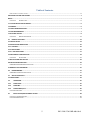
Table of Contents
FIRE ALARM CONTROL PANEL ...........................................................................................................................................0
FIRE ALARM SYSTEM LIMITATIONS ............................................................................................................................... 1
NOTES: ......................................................................................................................................................................... 4
CHAPTER 1:
INTRODUCTION .............................................................................................................................................6
1.1 SYSTEM DESIGN AND PLANNING ............................................................................................................................ 6
1.2 GENERAL ................................................................................................................................................................. 6
1.3 FIRE ALARM PROCEDURES ...................................................................................................................................... 7
1.4 USER RESPONSIBILITY ............................................................................................................................................. 7
1.5 ROUTINE TESTING ................................................................................................................................................... 8
CHAPTER 2:
2.1
PRODUCT DESCRIPTION ................................................................................................................................11
PRODUCT FEATURES: ......................................................................................................................................... 12
2.2 SPECIFICATION ...................................................................................................................................................... 14
2.3CONTROL AND INDICATIONS ................................................................................................................................. 16
2.3.1 CONTROLS.......................................................................................................................................................... 16
2.3.2 INDICATIONS ...................................................................................................................................................... 17
2.3.2.1 LED INDICATIONS ............................................................................................................................................ 17
2.4 MECHANICAL CONSTRUCTION .............................................................................................................................. 18
CHAPTER 3:
INSTALLATION.............................................................................................................................................22
3.1INSTALLATION PRECAUTION .................................................................................................................................. 22
INSTALLATION PRECAUTIONS ..................................................................................................................................... 22
CHAPTER 4: PROGRAMMING INSTRUCTIONS ..........................................................................................................................27
4.1MENU KEY FLOW DIAGRAM .................................................................................................................................. 27
4.2
PROGRAMMING: ............................................................................................................................................... 31
CHAPTER 5: OPERATING INSTRUCTIONS ................................................................................................................................42
5.1
SWITCH FUNCTIONS .......................................................................................................................................... 42
5.2 INDICATIONS ........................................................................................................................................................ 43
5.3
OPERATION ................................................................................................................................................... 45
5.3.1
ZONE FAULT: ................................................................................................................................................. 45
5.3.2
ZONE FIRE: .................................................................................................................................................... 45
5.3.3
ZONE DISABLE/W.T: ...................................................................................................................................... 46
CHAPTER 6: SERVICING: .......................................................................................................................................................48
6.1
INSTALLATION/REPLACEMENT OF PCB: ........................................................................................................ 48
CHAPTER 7: TROUBLE SHOOTING ...........................................................................................................................................50
CHAPTER 8: ABBREVATION ...................................................................................................................................................51
5
RE / DD / UM / RE-900 1.0-0
Chapter 1: Introduction
This manual is intended as a complete guide to the 1 Zone
Conventional Fire Control Panel. User operating Instructions are
provided in the first part of this manual. This is followed with sections
describing installation and commissioning procedures and full technical
details are provided.
1.1 System Design and Planning
It is assumed that the system, of which this control panel is a part,
has been designed by a competent fire alarm system designer in
accordance with the requirements of IS 2189: 1988 and any other local
codes of practice that are applicable. The design drawings should
clearly show the positions of the field devices and the control
equipment.
1.2 General
The panel is self-contained with integral power supply and space
provision for two sealed lead-acid standby batteries and comply with
the requirements of IS 2189: 1988. The panel functions are
microprocessor controlled and test and isolate functions are included.
Provision is made for a repeater function of panel status output. The
panel can accept, per zone, automatic detectors with a total
maximum loading of 2.4mA quiescent current rating (refer to chapter
2.2), and an unlimited number of manual call points.
End of Line (EOL) devices
The panels can continue to monitor manual call points with
detectors removed, providing the detectors are fitted with a Schottky
diode and an a EOL device is used.
Installation
The panel is easy to install and operate. Control functions Programming
functions are enabled by using password. The panel fascias are
retained by tamper-proof screws.
6
RE / DD / UM / RE-900 1.0-0
1.3 Fire Alarm Procedures
In accordance with IS 2189: 1988, written procedures should be laid
down for dealing with alarms of fire, fault warnings, and the isolation of
any part of the system. The responsible person should ensure that users
of the system are instructed in its proper use and are familiar with the
procedures.
On hearing the fire alarm:
CARRY OUT THE PRESCRIBED PROCEDURE Subsequent actions will
depend on the circumstances, and may include silencing the audible
alarms and resetting the system, as described later.
To Evacuate the premises:
Press the Evacuate key and enter the password to OPERATE SOUNDERS.
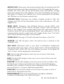
Fault Indication:
If the control panel indicates a Fault condition, make a note of all
illuminated indicators, refer to the chart on page 36, and call the
engineer.
1.4 User Responsibility
In addition to the routine testing described on routine test, the user has
a responsibility for ensuring certain actions are taken following a fire or
fault, and for implementing remedial action following a specified
incidence of false alarms. As a minimum, the user shall record any
incident and inform the service organization, who may be required to
retest the system. The user's responsibilities are described fully in IS 2189:
1988.
7
RE / DD / UM / RE-900 1.0-0
1.5 Routine Testing
In order to ensure that the system is fully operational, and to comply
with the requirements of IS 2189: 1988, the following routine attention is
recommended:
Daily - Check the panel to ascertain that it indicates normal operation.
If any fault is indicated check that it has been recorded and that the
appropriate actions have been taken, e.g. informing the maintaining
company.
Weekly - Test at least one detector or call point to confirm the
operation of the panel and the audible alarms. Test a different zone
each week and, if possible, a different device. Keep a record of the
device and zone tested each week. Record and report any
malfunction.
Quarterly - The responsible person should ensure that every three
months the system is checked by a competent person. Check the
standby batteries and the charger voltage Test at least one device in
each zone to check the panel functions. Check the operation of the
audible alarms and any link to a remote manned centre, Central
Station, etc. Carry out a visual inspection of the installation to check for
alterations or obstructions and issue a certificate of testing.
Annually - The responsible person should ensure that, in addition to the
quarterly checks, each device on the system is tested and that a visual
inspection is made of the cable fittings and equipment.
Note: The control panel case should be cleaned periodically by wiping
with a soft, damp cloth. Do not use any solvents.
8
RE / DD / UM / RE-900 1.0-0
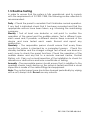
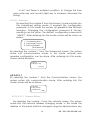
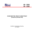
Mother Board Terminals and connectors
Power Supply Board Terminals and connectors
9
RE / DD / UM / RE-900 1.0-0
10
RE / DD / UM / RE-900 1.0-0
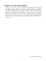
Chapter 2: Product Description
The RE – 900 is a 12 – 128 zone microprocessor based conventional
Fire Alarm Control Panel. The Panel accepts water flow devices,
conventional input devices like 2 wire smoke detectors, pull stations
and other normally open contact devices. The Outputs include
notification appliance circuits (NACs / sounders), Two Form –C relays
for Fire and one relay for fault. And also communication port RS485 to
interface with remote annunciator. This panel is field programmable
via the front panel keypad. It supervises all wiring, AC voltage and
Battery level.
11
RE / DD / UM / RE-900 1.0-0
2.1 Product Features:
Touch Keypad for user friendly operation.
Complies with UL -864 and NFPA-72.
Epoxy powder coated finish.
Operates on 120 - 220v 60 /50 Hz, AC Mains power supply.
12 -128 Class B Style ‘B ‘or Style ’C’ initiating device circuit (IDC).
All zones accept smoke detectors and any normally open
contact device.
Class B Notification Appliance Circuits (NAC).
NAC shall be programmed as auto silence / Silence Inhibit.
Standby (battery) backup 24v DC power supply with builtin
charger.
Error free Fire / Fault status in unambiguous colored LED indication.
1000 Event storage with RTC.
Main, Standby status with audible and visual indication.
Two FormC relays for fire and fault.
Resettable / Steady 24V D.C. Output.
RS 485 Communication facility (Optional).
TCP/IP (Optional) facility.
Walk Test facility.
Zone Wise Sounder/Contact via RS 485.
All field wiring circuits are Power limited except 110 - 220v AC
and Battery.
12
RE / DD / UM / RE-900 1.0-0
All field wiring circuits are supervised.
Zone Isolation facility with loop voltage cut off.
Earth fault annunciation facility at 0 ohms.
Programmable AC loss delay.
Programmable Trouble reminder.
Peer to Peer Networkable
Repeater connectivity via Rs485.
13
RE / DD / UM / RE-900 1.0-0
2.2 Specification
AC Power
110 - 220 VAC, 50 Hz, +10%, -15%.
Wire size: 1.5 Sq. mm with 600 V insulation
Standby power
24VDC as required
Operating Condition:
Operating Temperature 0 - 49° C/32-120° F.
Relative Humidity 93 ± 2% RH (noncondensing)
at 32 ±2° C/90 ±3° F.
Battery (Lead Acid only)
Constant Voltage – 28.0v± 0.5V
Charging Current as required
Charging Capacity: 7 Amp Hour Battery (Higher size are request).
System Quiescent Current: 50mA + (4.4 – 6.8mA per zone)
D.C. output
Operating Voltage: 24VDC(Resettable / Steady), 500mA Max.
Initiating Device Circuits (Zone Circuit)
All zones are Class B, Style B / C operation
Normal Operating Voltage: 14 - 24 VDC
Alarm Current: 15 – 35mA threshold
Short Circuit Current: 45mA Maximum
Loop resistance: 100 ohms Maximum
End-Of-Line Resistor: 4K7, 1/2 watt
Standby Current: 7 mA (2.5 mA for Detectors)
14
RE / DD / UM / RE-900 1.0-0
Notification Appliance Circuits (Sounder Circuit)
Class – B, Style – Y wiring
Operating Nominal Voltage: 24 VDC Special Application
Current for all NACs: 2A (1 A per Circuit)
Line Drop: 1.8V
End-Of-Line Resistor: 4K7, 1/2 watt
Common Relays:
Type
: Form C
No of Relays
:2
Relay Contact Rating
: 2Amps @ 30VDC
0.5Amps @ 125VAC
Power factor
: 1.0
RS485 Communication Port
Max. Distance:
1.5Km Max.
15
RE / DD / UM / RE-900 1.0-0
2.3Control and Indications
2.3.1 Controls
ACK. Key:
To mute local buzzer in alarm condition.
To mute local buzzer in Supervisory or fault condition.
User or Admin password protected.
SILENCE Key:
To silence the external NACs in Fire Condition.
User or Admin password protected.
RESET Key:
To reset the particular zones in Fire alarm or Latched Supervisory
condition.
User or Admin password protected.
Possible to access only after silence in alarm condition.
EVACUATE:
To activate External NACs Manually.
User or Admin password protected.
16
RE / DD / UM / RE-900 1.0-0
CURSOR KEYS:
To move the cursor point in the LCD as required.
ENTER Key:
To accept the programmed or edited menu, mode or value in the
LCD.
MENU Key:
To enter into the Main Menu in the LCD.
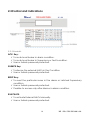
2.3.2 Indications
2.3.2.1 LED Indications
Fire - Red
Fault-Yellow
System On – Green
Charger Fault - Yellow
Mains Fail-Yellow
System Fault-Yellow
Battery Fault-Yellow
Earth Fault-Yellow
Silenced-Yellow
NAC Fault-Yellow
Zone Disable/W.T – Yellow
2.3.2.1
LCD Indication
The LCD is mainly used for the programming of the panel. It also
indicates all events along with the LED indications except system on
and system fault.
2.3.2.2
Local Buzzer
A piezo buzzer provides separate and distinct sounds for alarm,
trouble and supervisory conditions:
Alarm – Continuous
Fault – pulse 0.5sec ON and 5sec OFF
17
RE / DD / UM / RE-900 1.0-0
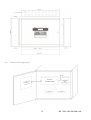
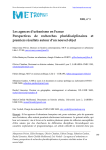
2.4 Mechanical Construction
The enclosure of the Panel is constructed by 18 gauge (1.22mm)
CRCA sheet with powder-coated finish. The 19mm [20No’s] for Indian
Std.) 20no’s of knockouts are given for cable entry at the top of the
cabinet. The lockable hinged door is provided to access the inside the
cabinet. The panel also has sufficient space to accommodate 2 Nos. of
12v, 7Ah batteries.
18
RE / DD / UM / RE-900 1.0-0
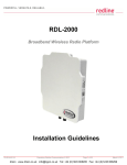
2.6
Internal Arrangement
19
RE / DD / UM / RE-900 1.0-0
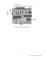
2.7
Components
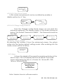
Master Board (RE-900-16Z-MB)
The Master board contains the primary components and wiring interface
connectors. Display Board (RE-900-DISP-R1.1)The Display Board contains the system
CPU, LED Display, LCDunit and Control keys.
Display Board (RE-900-DISP-R1.1)
20
RE / DD / UM / RE-900 1.0-0
Power Supply Board (RE-900-PS)
21
RE / DD / UM / RE-900 1.0-0
Chapter 3: Installation
3.1Installation Precaution
Installation Precautions
WARNING - Several different sources of power can be
connected to the fire alarm control panel. Disconnect
all sources of power before servicing. Control unit and
associated equipment may be damaged by removing
and/or inserting cards, modules, or interconnecting
cables while the unit is energized. Do not attempt to
install, service, or operate this unit until this manual is
read and understood.
CAUTION - System Reacceptance Test after Software
Changes. To ensure proper system operation, this
product must be tested in accordance with NFPA 72
after any programming operation or change in sitespecific software. Reacceptance testing is required
after any change, addition or deletion of system
components, or after any modification, repair or
adjustment to system hardware or wiring.
All
components, circuits, system operations, or software
functions known to be affected by a change must be
100%
tested. In addition, to ensure that other
operations are not inadvertently affected, at least 10%
of initiating devices that are not directly affected by
the change, up to a maximum of 50 devices, must also
be tested and proper system operation verified.
This system meets NFPA requirements for indoor dry
operation at 0-49° C/32-120° F and at a relative
humidity of 93 ±2% RH (non-condensing) at 32 ±2° C/90
±3° F. However, the useful life of the system's standby
batteries and the electronic components may be
adversely affected by extreme temperature ranges
and humidity. Therefore, it is recommended that this
system and all peripherals be installed in an
environment with a nominal room temperature of 1527° C/60-80° F.
22
RE / DD / UM / RE-900 1.0-0
Verify that wire sizes are adequate for all initiating and
Indicating device loops. Most devices cannot tolerate more than a 10%
I.R. drop from the specified device voltage.
Adherence to the following will aid in problem-free
installation with long-term reliability:
Like all solid-state electronic devices, this system may
operate erratically or can be damaged when subjected to lightninginduced transients. Although no system is completely immune from
lightning transients and interferences, proper grounding will reduce
susceptibility. Overhead or outside aerial wiring is not recommended,
due to an increased susceptibility to nearby lightning strikes. Consult
with the Technical Services Department if any problems are
anticipated or encountered.
Disconnect AC power and batteries prior to removing or inserting circuit
boards. Failure to do so can damage circuits.
Remove all electronic assemblies prior to any drilling, filing, reaming, or
punching of the enclosure. When possible, make all cable entries from
the sides or rear. Before making modifications, verify that they will not
interfere with battery, transformer, and printed circuit board location.
Do not tighten screw terminals more than 9 in-lbs.
Over-tightening may damage threads, resulting in reduced terminal
contact pressure and difficulty with screw terminal removal.
Though designed to last many years, system components
can fail at any time. This system contains static-sensitive
components. Always ground yourself with a proper wrist strap before
handling any circuits so that static charges are removed from the
body. Use static-suppressive packaging to protect electronic
assemblies removed from the unit.
Follow the instructions in the installation, operating, and
programming manuals. These instructions must be followed to avoid
damage to the control panel and associated equipment. FACP
operation and reliability depend upon proper installation by authorized
personnel.
23
RE / DD / UM / RE-900 1.0-0
3.2 Input Circuits
The control panel has 12 – 128 zone input circuits. The maximum loop
resistance limit for each input circuit is 100 ohms. All field wiring of
each zone is supervised for opens and ground faults. Both conditions
are visually and audibly (toggle tone) annunciated.
Each zone is a Class B Initiating Device Circuit (IDC – Zones) designed
to accept any normally open contact devices and conventional 2wire, 24 volt smoke detectors.
It is allowable to mix an assortment of device types (i.e. smoke
detectors, heat detectors, pull stations, etc.) on any zone.
24
RE / DD / UM / RE-900 1.0-0
3.3 Output Circuits
Nonresettable Power (500mA) 24 VDC filtered, nonresettable power
can be obtained from 24v DC out Terminals.
Sounder Circuits
The RE - 900 provides Notification Appliance Circuits (NAC) standard as
Class B. This circuit is capable of a maximum of 0.2 amps of current per
zone.
25
RE / DD / UM / RE-900 1.0-0
Standard Relay
The control panel provides three Form-C relays rated for 2.0 amps @ 30
VDC and 2.0 amps @ 30 VAC.
Relay connections may be power-limited or nonpower-limited, provided that a
minimum of 0.25" is maintained between conductors of power-limited and nonpowerlimited circuits.
26
RE / DD / UM / RE-900 1.0-0
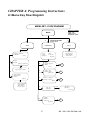
CHAPTER 4: Programming Instructions
4.1Menu Key Flow Diagram
MENU KEY - FLOW DIAGRAM
DEFAULT PASSWORD
M ENU
ADM IN
PASSWORD REQUIRED
(Default: 54321)
1
2
VIEW
PROG RAM
1. Supp r ess ed Even ts
2. HIST ORY
[View ]
USER - 1234
ADM IN - 54321
ADVANCED - 654321
1. Zo ne
2. Re lay
5.Common
3
About
Rav el Ele ctron ics
Fire A lar m Pane l
Mode l : RE-900
16 Z one Pa nel
3. Nacs
4 . 24 V O/ P
[ Pr ogra m]
1
1.Fa ults
2. A la r m
Ev ent
Su ppre sse d Co ndition
2
1 . V ie w A ll Eve nts
2 . A la rm Even ts
3 . Delete
[His tor y]
Evt No : XXX/Z Z Z
Da te: dd/mm/yy
T ime: hh:mm:ss
Even ts : Eve nt
1. Mod e
2. L oca tio n Pro gr am
3. W irin g
[ Z one ]
1
[S uppre sse d Ev ent s]
2
1. Rela y 1 : Fire
2. Rela y 2 : Fa ult
[Relay O/P]
3
B
1. NA C 1 : T emporal
2. NA C 2 : Co ntin ue
[NAC s]
C
Pr ess #
4
5
A
24 V O/ P
<<Ste ady >>
[24 V O/P*]
24 V O/ P
<<Ste ady >>
1 . Set tin gs
2 . Fe atu re s
3 . A dva nce d
[ Common]
27
D
RE / DD / UM / RE-900 1.0-0
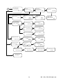
1
Zone 4
( #E dit)
[Mode]
Zone 4
E nable
[Mode]
Zone 2
First Fl oor (#Edi t)
Zone 2
Second Floor B win g
E nter No of Zone?004
A
2
Enter No of Zone?002
A
T ype: Cla ss - B
St yle : B
( #Ed it)
[W irin g]
3
Wiring
A
Ty pe: Class - B
S tyle :C
1
Relay 1: Fire
B
Type: F ire
( Relay O/ P1)
T ype: Fault
#
( Re lay O/P1)
2
T ype: Fault
Re lay 2: Fault
B
1 &2
C
(Re lay O/P2)
M ode
<< T emp o ra l> >
[#.Edit ] [
S ave
T ype: F ire
#
( Relay O/P2)
Mode
<<Synchronize d>>
[#.Edit ] [
Save ]
]
[ NA C1*]
[ N AC 1 *]
Mode
<<Continuous>>
[#.Edit ] [
Sav e ]
[ NA C1*]
1
D
1. Caption
2. Date & Time
3. Pas sw ord
1
[Se ttin g]
Mode
<<BPM 60>>
[#.Edit ] [
Sav e ]
[ NA C1*]
Cap tio n :
Rav el Ele ctron ics
(#. Edit)
[Ca ption]
Capt ion :
A BC
Rave l Elec tronics
Dat e : d d / mm / y y
Time: hh : mm : s s
[# Edit]
[R TC]
Da te : dd / mm / yy
T ime: hh : mm : ss
[
Sav e]
[RTC]
[Cap tio n]
3
2
G
D
2
AC Loss De lay
Enable d : 120 Min
[
Save ]
[Fe ature 1 *]
AC Loss De lay
Disable d
[
Save ]
[Fe ature1 *]
28
RE / DD / UM / RE-900 1.0-0
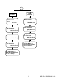
D
3
2
1. Co mmun ic atio n
2. Pass w or d Ct rl
3. Facto ry Def a ult
[A dva nce d]
1
#
[# Edit]
{ N/W PNL ]
1) Fir e O. P:Disabled
2) Fault O/P: Dis abled
3) NAC's : Disa ble d
[ N/W O/P *]
1
#
F ire O/P:<Disab led >
Fau lt O/P : <Disab le d>
#
En ter Re p. Pane l No?
NA C's O/P : <Disab led >
Repe ate r Pane l No : 0 5
Dis abled
[# Edit]
[Rep Pnl]
[Rep Conf ig]
2
1. User A c ces s Ctrl
2. Chg Conf ig Pa ss
[ Pas s Ctr l]
1
[N/W Ad dr ]
1. N/W A dd r :05
2. Netw o r k St atus
3. N/W O/P Conf ig
[N/ W]
F ire O/P:<En able>
Use r Pass w ord
<<Disa ble >>
(# Edit )
[
Sav e]
Fa ult O/ P : <En able>
[N / W O/P FT*]
#
[ N / W O/P NA C*]
2
Pa nel No: 4
Dis able
N/W Ad dr ?
[N / W O/P F R*]
[N / W O/ P FT*]
3
1
[# Edit]
{ N/W PNL]
[N / W O/P F R]
2
1. N/W A dd r:
2. Netw o rk St atus
3. N/W O/P Conf ig
[N/W ]
Pan el No: 4
Ena ble
En ter Pa nel No ?
[Mod e]
3
1
1.Ne tw ork
2. Re pea ter Co nf ig
(Common)
Fau lt O/ P : < Ena ble >
[N / W O/P NA C*]
#
Re pea ter Pa nel No : 05
Enable
[ # Ed it]
[Re p Pnl]
Us er Pa ssw o rd
Disa ble d
[ # Ed it]
[Use r Pas s Ctr l ]
2
Old Pas sw or d ?
[Chg Conf ig Pa ss]
3
New Pass w or d?
[Ch g Co nf ig Pas s]
Re - New Pass w or d?
[Chg Conf ig Pass ]
Re - Ne w Pa ssw ord
Upda ted
Fac tor y D ef ault
Rec ove ring ..... .
29
RE / DD / UM / RE-900 1.0-0
G
1. USER
PASSWORD
1.User1 4. User 4
2.User2 5. USer 5
3.User3
[ User Pass ]
Old Password?
[chg Usr1 Pass]
New Password?
[chg Usr1 Pass]
Re-Type New?
[chg Usr1 Pass]
2. ADMIN
PASSWORD
Old Password?
[Chg Adm Pass]
New Password?
[Chg Adm Pass]
Re-Type Ne w?
[Chg Adm Pass]
Re-Type Ne w? *****
New Password updated
Pre ss '#' to chge
Re-Type New? ****
New Password updated
Pre ss '#' to chge
30
RE / DD / UM / RE-900 1.0-0
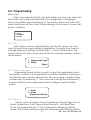
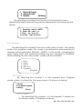
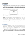
4.2 Programming:
Menu Key
Menu is accessed by both user and admin, but user can enter into
test mode only using user password. The configuration changing is
done using admin password (level 3). The various steps involved in this
menu are shown as flow chart. After entering into the menu, screen will
shown as follows,
1. View
2. Program
3. About
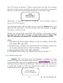
4.2.1 View:
View Option can be accessible by User. By this option user can
view the past history and exiting configuration, however they cannot
change preserved settings. By selecting ‘1’ when in Main menu, the
system enters into View mode and shows the viewing category options
as like below,
1. Suppressed Events
2. History
[View]
4.2.1.1.Suppressed Events
Suppressed Events option is used to view the suppressed events
during Fire condition. The suppressed events like PreAlarm, Supervisory
and faults events can be viewed from this menu using corresponding
number keys. By selecting ‘1’ from view menu brings the suppressed
events and shows the suppressed events category options as like
below.
1. Faults
2. Alarm
[Suppressed Events]
4.2.1.2.History
History option is used to view the past panel event logs such as
Alarm, Supervisory, Fault, Silence Reset and etc., with Real Time
Clock. By pressing the key ‘2’ from View menu brings the History
mode. The history mode provides the following event filtering option,
31
RE / DD / UM / RE-900 1.0-0
1. View All Events
2. Alarm Events
3. Delete
[History]
By selecting a number from the list in the the history menu,
respected subject relevant logs alone displayed in the screen as like
below,
1. Event No: abcd / ABCD
2. Date: dd / mm / yy
3. Time: hh / mm / ss
4. Events: Type of Event
4.2.2 Program:
By selecting the number 2 from the main menu screen, the system
enters into program mode. This mode is protected by password and it
requires admin password (Default – 54321). In this mode, changing the
zone, Relay, NAC and password setting can be changed or modified.
After entering into the view mode, screen will be as below.
1.
2.
3.
4.
5.
Zone
Relay
NAC's
24V O/P
Common
[Program]
4.2.2.1 Zone
By selecting the number 1 in the keypad from Program
mode screen, it enters into the zone screen. It is shown as below:
1. Mode
2. Location Program
3. Wiring
[Zone]
4.2.2.1.1 Mode
By selecting the number 1 in the keypad, it enters into
the Mode screen. It Displays as follows.
32
RE / DD / UM / RE-900 1.0-0
Enter Zone No.? AA
Press # to change
Press Enter to Set
AA = Number of panel to be selected.
4.2.2.1.2 Location Program
By selecting the number 2 in the keypad from setting , it
enters into the location program Mode screen. When
entering into this it will ask the zone number. After entering
the zone number press ENTER key, cursors goes to next line.
Then enter the location using the number / letter key pad,
press ENTER key after entering location.
Enter Zone No.? AA
Press # to change
Press Enter to Set
Zone 1
<Loc. not entered>
4.2.2.1.3 Wiring
From the Zone Wiring program screen, The zones circuit is
designed for the class-B wiring. The style of wiring can be changed
using this option. The Style of class-B can be changed as Style-B or StyleC by pressing ‘#’ key from the panel key pad. When you enter into this
mode the screen will be as below.
Type: Wiring
Class : B
(# Edit)
(wiring)
33
RE / DD / UM / RE-900 1.0-0
4.2.2.2 Relay
By selecting the number 2 in the keypad, it enters into the Relay
screen. It Displays as follows.
1. Relay 1: Fire
2. Relay 2: Fault
[Relay O/P]
By selecting the number 1 in the keypad, it enters into the Fire
Relay screen. It Displays as follows.
1. Type : Fire
[Relay O/P1]
4.2.2.3.1 NAC -1
The NAC1 output can be configured as Temporal,
Synchronized, Continuous, 60 BPM. In Temporal and synchronize
mode the NAC1 output will be as pulse as shown below. In these
modes all the Sounders will be evacuated simultaneously.
To change the option press ‘#’ key to toggle between the
options Steady, Temporal, Synchronized. The NAC’s should be in
off condition to change the options.
34
RE / DD / UM / RE-900 1.0-0
4.2.2.3.2 NAC -2
The NAC2 output can be configured as Continuos,
Temporal, Synchronized & 60 BPM. In Temporal and synchronize
mode the NAC2 Output will be as pulse as shown below. In these
modes all the Sounders will be evacuated simultaneously.
To change the option press ‘Change’ key to toggle
between the options Continuous, Temporal, Synchronized &
60BPM. The NAC’s should be in off condition to change the
options.
4.2.2.4 24V Output
The 24V output can be configured as Resettable or steady.
If four wire detectors are used in the panel, then the 24V DC
output should be configured as Resettable. While resetting the
panel this output will cut off for the 3 seconds. . The default
setting is Steady Output. In this mode screen display as below.
24V Output
Steady
To change the option press ‘#’ key to toggle between the
options Steady and resettable.
4.2.2.5 Common
By selecting the number 4 in the keypad, it enters into the
Common screen. It Displays as follows.
1. Settings
2. Features
3. Advanced
[Common]
By selecting the number 1 in the keypad, it enters into the
Setting mode. It Displays as follows.
35
RE / DD / UM / RE-900 1.0-0
1. Caption
2. Date & Time
3. Password
[Setting]
4.2.2.5.1 Caption
By selecting the number 1 from the system screen,
the system enters into Caption editing mode. In this
mode, caption is changed by using ‘#’ key, maximum
20 characters can entered which will be display in front
screen in system healthy mode. After entering into this
mode, screen will be as below.
Caption:
Ravel Electronics
(#Edit)
[Caption]
4.2.2.5.2 Date & Time
By selecting the number 2 from the setting screen,
the system enters into RTC settings mode. In this mode,
time and date settings are changed by using ‘#’ key.
After entering into this mode, screen will be as below.
Date: DD / MM / YY
Time: HH / MM / SS
(#Edit)
[RTC]
.
4.2.2.5.3.1
User Password
By selecting the number 3 from the Setting screen,
the system enters into user password change mode. In
this mode, admin password can be changed by
selecting corresponding number, after entering into this
mode, screen will be as below.
1. User 1
2. User 2
3. User 3
4. User 4
5. User 5
[Chg Pass]
36
RE / DD / UM / RE-900 1.0-0
After
selecting
corresponding
changing screen as follows:
number,
password
Old Password ?
[Chg XXX Pass]
XXX – User 1/2/3/4/5
New Password ?
[Chg XXX Pass]
Re type New Password ?
[Chg XXX Pass]
New Password Updated
[Press # to change]
4.2.2.5.3.2
Admin Password
From the Admin Password Mode screen, By pressing the
‘enter’ key from the change Admin Password screen, system
enters into the Admin Password change mode. The display
screen of this mode showed as below. The Default Password
is”54321”. The Password should be five digit.
37
RE / DD / UM / RE-900 1.0-0
Old Password ?
[Chg Adm Pass]
New Password ?
[Chg Adm Pass]
Re Type New Password ?
[Chg Adm Pass]
New Password Updated
[Press # to change]
4.2.2.4.2
AC Loss Delay
When AC power is lost, the control panel trouble relay will
activate. The factory default option for this feature is Enabled,
the trouble relay activation on AC loss after the time delay
setting. Press ’Change’ key to toggle between enabled /
disabled option. The AC Loss Delay timing can set 001 to 999min.
After setting the required time press Enter key to accept the
time. The default time is 120 Seconds. When you enter into this
mode the screen will be as below.
9. AC Loss Delay
<120 (Min)>
38
RE / DD / UM / RE-900 1.0-0
In AC Loss Delay is enabled condition, to change the time
press enter key and use left /right key to increase/ decrease the
timing.
4.2.2.4.3 Advanced
By selecting the number 3 from the Screen, it system enters into
the Advanced setting mode. It required the configuration
password. In this mode the system up gradation like Network
selection, Changing the configuration password & Factory
resetting can be done. The default configuration password is
“654321”. After entering into the mode, screen will be shown as
below.
1. Communication
2. Password Control
3. Factory Default
[Adv anced]
By selecting the number 1 from the Advanced screen, the system
enters into communication mode. In this mode, network and
repeater configuration can be done. After entering into this mode,
screen will be as below.
1. Netw ork
2 .Repeater Config
[Common]
4.2.2.4.3.1.1
By selecting the number 1 from the Communication screen, the
system enters into communication mode. After entering into this
mode, screen will be as below.
1. N/W Addr:
2. Netw ork Status
3. N/W O/P Config
[N/W]
4.2.2.4.3.1.1.1 Network Address
By selecting the number 1 from the network screen, the system
enters into the network address changing mode. In this mode the
address of the panel shall be changed using the alphanumeric key
39
RE / DD / UM / RE-900 1.0-0
pad. The address of the panels should be in the range 1 to 32. After
entering into this mode, the screen will as shown below.
N/W Addr ?
[N/W Addr]
Note: Make sure the address of the panel is not repeated.
4.2.2.4.3.1.1.2 Network Status
By selecting the number 2 from the network screen, the system
enters into the network status mode. In this mode the network
selection can be enabled / disabled by using up and down arrow
keys in the selected panel address. After entering into this mode,
screen will as shown below.
Pane l No: 4
Enab le
En ter Pa nel No: ?
[Edit]
[N.W Pane l]
[Mode]
4.2.2.4.3.1.1.3 Network Output Config
By selecting the number 3 from the network screen, the system
enters into the network Output configuration. After entering into this
mode, screen will as shown below.
1) Fire O.P:Disabled
2) Fault O/P: Disabled
3) NAC's : Disabled
[N/W O/P *]
4.2.2.4.3.1.2 Repeater Configuration
The Repeater configuration is used to configure the repeater panel.
The repeater panel can be enable or disable by switching the # key.
The LCD display of the screen is shown below.
Ente r Rep. Pan el No?
[Re p Co nf ig ]
Re pea ter Pa nel No : 05
Disab led
[ # Ed it]
[Re p Pnl]
#
Rep eate r Pan el No : 0 5
Ena ble
[# Edit]
[Rep Pnl]
4.2.2.4.3.2 Password Control
By selecting the number 2 from the advanced screen, the system
enters into the password control. In this stage user & Advance
password can be reset. After entering into this mode, screen will as
shown below.
40
RE / DD / UM / RE-900 1.0-0
1. User Access Ctrl
2. Chg Config Pass
[Pass Ctrl]
4.2.2.4.3.2.1 User Access Control
In this mode user password can be controlled by enable or
disable options by ‘#’ key.
User Pass w ord
<<Disab le> >
(# Ed it)
[
Save ]
Use r Pas sw o rd
Disab led
[# Ed it]
[Use r Pas s Ctrl ]
4.2.2.4.3.2.2 Change Config Password
From the Change config Mode screen we can reset the
advance password. The display screen of this mode showed as
below. The Default Password is”654321”. The Password should be
five digit.
Old Pass w ord?
[Ch g Co nf ig Pas s]
Ne w Pa ssw o rd?
Re - Ne w Pa ssw o rd?
[Chg Conf ig Pass ]
[ Chg Co nf ig Pas s]
Re - New Pass w ord
Up date d
4.2.2.4.3.2 Factory Default
By selecting the number 3 from the advanced screen, the system
enters into the factory default setting mode. After entering into this
mode, screen will be as below.
Factory Default
Recovering ......
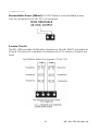
4.2.3 About
It shows the details of the panel by pressing enter key in the
about menu. The LCD display will show as below. The model
shown with respect to the no. of zones, for 16 zone RE – 90016Zone, 32Zone RE-900
Fire Alarm Panel
Model: RE-900
Ver 1.0
16 Zone Panel
Note: Version shown is software version.
41
RE / DD / UM / RE-900 1.0-0
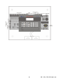
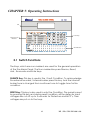
CHAPTER 5: Operating Instructions
LCD
Control Keys
Common & Power
Indications
Zone Indications
5.1 Switch Functions
The Keys, which are non-masked, are used for the general operation
of the Fire Alarm Panel. The Non-masked keys are Silence, Reset,
Ack., Evacuate and Enter keys.
SILENCE Key: This key is used in Fire / Fault Condition. To acknowledge
the external sounder / internal buzzer press this key. And the internal
buzzer tone is changed from continues tone to toggle tone for fire
condition.
RESET Key: This key is also used in only Fire Condition. The panel is reset
by pressing this key and during reset condition, all the detector input
voltages are cut off up to 3 seconds for Detectors and MCP’s, Then
voltages are put on to the loop.
42
RE / DD / UM / RE-900 1.0-0
EVACUATE Key: This key is used to energize the external hooters
without actual fire.
ENTER KEY: This key is used to accept the password during silence, reset
in Fire Condition And also used for the Evacuate. This key is used to
check the all LED’s in panel is in good condition with continues buzzer
tone.
MENU Key: This key is used to get into the program menu and get
back to the previous menu screen.
ACK. Key: This key is used to acknowledge the buzzer tone during
the fault and fire condition. This key can be operated with user or
admin password.
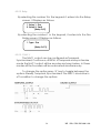
5.2 Indications
SYSTEM ON: This LED will glow when the panel is energized by primary
and standby power. This is the only LED glowing in the normal
monitoring condition. The LCD Display as shown below.
FIRE ALARM
SYSTEM HEALTHY
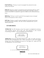
MAINS FAIL: Whenever the Main Supply (110 - 220v A.C) fails, the Mains
fail LED will be illuminated and it also indicated in LCD with toggle
Buzzer tone. The LCD Display as shown in the figure 22, ‘Mains fail’ will
be displayed in the fault screen.
Fault [ x/y ]
Type of Fault
x – nth no. of fault; y – Total no. of fault.
Figure – 22
43
RE / DD / UM / RE-900 1.0-0
BATTERY FAULT: Whenever the backup battery fails, the battery fault LED
will be illuminated and it also indicated in LCD with toggle Buzzer tone.
Similarly the same LED will be illuminated when the battery voltage
goes down below the 21.6v (Battery Low). The LCD Display as shown in
the figure 22 ‘Battery Fail / Battery Low’ will be displayed in the Battery
fail / Battery low fault screen respectively.
CHARGER FAULT: Whenever the battery charger section is fails, the
charger fault LED will be illuminated and it also indicated in LCD with
toggle tone.
EARTH FAULT: Whenever the Initiating Device circuits (IDCs) and
Notification Alarm Circuits (NACs) are gets contact with the Earth or
Body of the cabinet, the corresponding fault LED, earth fault LED and
common fault LED will be illuminated and it also indicated in LCD as
corresponding circuit is earth fault with toggle Buzzer tone. The Earth
fault can be created through 0 Ohms resistor.
SYSTEM FAULT: Glowing of this LED indicates the failure of the CPU.
SILENCED: This LED will glow when the silence key is pressed in fire
condition only.
NAC FAULT: Whenever there is any fault in Notification Appliances
Circuits like NAC loop Open / Short / Earth fault, it will be identified by
COMMON NAC FAULT LED. The LCD Display as shown in the figure 22,
‘NAC # Fault’ will be displayed in fault screen.
FIRE: This twin fire LED will glow when any one or more of the zones
are in fire condition.
FAULT: This fault LED will glow when any one or more of the zones are
in fault condition.
ZONE FIRE: This fire LED will glow when the zones are fire condition. The
first fired zone continuously in blink and other zone fire LED will glow
steadily in fire condition. The fired zone is displayed in the LCD, first fire
zone and total no. of zone is displayed separately.
ZONE FAULT: This fault LED will glow when there is an open or short or
earth fault in that particular zone.
ZONE DISABLE/W.T: This zone wise LED glows steadily in disabled
condition and blinking in the Walk test mode.
44
RE / DD / UM / RE-900 1.0-0
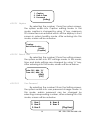
5.3 Operation
5.3.1 ZONE FAULT:
When faults like Open/ Short occurred in the loop, the corresponding
ZONE FAULT LED would identify it.
And in the output to main panel shows high resistance (Open),
hence in the main panel where this sector panel is connected shows
fault.
During above condition LCD Show as follows and by using the
curser key the suppressed fault can be viewed.
[A/B]
OPEN /SHORT IN ZONE X
Zone Location
Where A – nth Fault; B – Total No. of Fault; X – Zone Number which is
shown in LCD at present.
Note: During the above fault conditions, apart from the
specific fault identification LED, common fault, common
fault relay and Local buzzer with intermittent tone will be
activated. During this time, if ‘ACK.’ is activated, intermittent
tone will be silenced. By using ‘*’ key type of hidden fault
can be viewed.
5.3.2 ZONE FIRE:
When the control panel detects Fire via the Detector / MCP, the
corresponding ZONE FIRE red LED will be illuminated. At the same
time hooter, potential free contact and local buzzer (continuous
tone) will be activated. The common Fire LED will illuminate
whenever any zone is goes to fire condition.
And in the output to main panel shows Fire resistance (560 Ω),
hence in the main panel where this sector panel is connected shows
fire.
45
RE / DD / UM / RE-900 1.0-0
The LCD shows as follows. If there is more than one fire, the number
of zones in fire (shown as (Z##)) and in which zone first or recent fire
(Shown as Z##) occurred will be displayed on the fire screen.
[A/B]
FIRE IN ZONE X
Zone Location
Where A – nth Fire; B – Total No. of Fire; X – Zone Number which is
shown in LCD at present
The External hooter will be silenced by using the Silence Key and
silenced LED indicates it. But the buzzer tone will change to toggle
tone from continues tone.
Always the recent fired zone FIRE LED will blink continuously, rest of
the fired zone FIRE LED’s will glow constantly till it goes to RESET. The
FIRE LED indication will remain ON condition till the panel is RESET.
Note:
1. The Fire and Fault relay will be in ON condition till the fire
and fault LED’s go OFF.
2. By silencing, hooters are switched off and relay output for
actuators will remains in ON Condition until reset.
3. Always Recent fire zone LED will blink.
4. The other fire zones can viewed by using the key ‘*’.
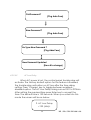
5.3.3 ZONE Disable/W.T:
Disable: The any Zone can be Disabled / Enabled in zone
mode through the programming section 4.2.1 Page 35. The ON
status indicates, the zone is disabled and the OFF status of the LED
indicates the enabled and blinking of that LED indicates the zone is
in walk test mode. In LCD the suppressed events are viewed in
suppressed events from menu screen.
Fault [XX/YY]
Zone X Disabled
46
RE / DD / UM / RE-900 1.0-0
XX – nth no. of events; YY – Total no. of events; X – Zone No.
Disabled.
Walk Test: Disable/W.T LED Blinking identifies the corresponding
Zone, which is under walktest. If this LED is illuminates continuously
then it identifies that particular zone is disabled. The walk test mode
helps the user to test each device in that particular zone by a single
person. During walk test mode, if any Fire is identified, the panel will
be silenced and reset automatically after 4 seconds and 2 seconds
respectively. In case of any other zone fire during this period, it is
considered as actual fire and it comes out from the walk test mode.
The LCD Display is as shown below.
WT: Fire [XX/YY]
Zone X
For More than One zone in Walk test fire condition, the screen
as follows,
WT: Fire [XX/YY]
1st: aa Zone X Rt: bb
Note:
a. If there is no more testing please ensure that the zone is brought
back to the normal Condition.
b. During in this mode, the Fire Relay will not be activated while in
fire condition.
c. If the zone is kept in Walk test mode for 10 minutes with out any
test the panel comes out of the walk test mode automatically.
d. In other zone gets fire, the walk test mode automatically
removed.
Restoral: When the zone restored to normal condition from
disable / Walk test mode, the zone which are all in disable/W.T
mode the corresponding LED’s goes off.
47
RE / DD / UM / RE-900 1.0-0
Chapter 6: Servicing:
6.1 Installation/Replacement of PCB:
Remove the screws of PCB, which has to be change and remove
the PCB from the mounting position and place the new PCB in that
same position as shown below.
Mounting position for Main Circuit board (RE – 900 – 16Z – MB):
Cable Entry Knock out
Mounting Hole
Mounting Hole
12V 12AH Battery
48
12V 12AH Battery
RE / DD / UM / RE-900 1.0-0
Mounting position for Display board (RE – 900 – DISP – R1.1):
Door Fixing Screws
PCB
Mounting Hole
PCB
Mounting Hole
Mounting
position
for
Display
board
(RE
–
900
–
PS
):
Cable Entry Knock out
Zone Board Mounting Hole
Power Supply Mounting Hole
12V 12AH Battery
12V 12AH Battery
49
RE / DD / UM / RE-900 1.0-0
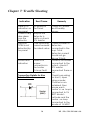
Chapter 7: Trouble Shooting
Indication
Root Cause
There is no
indication on
the panel
If there is any
false alarm
from the
detector
Detector
OPEN is not
detected by
the panel
No power to
the Panel
Hooter fault
indication
There is no
proper
connection in
the hooter
Or loop Fault.
May be the
detector is
faulty or check
EOL resistor
Total zone loop
current exceed
the rated value
Connection Details for Non
Polarized Hooter
50
Remedy
Check AC power
and Standby
power.
Check number of
detectors
connected in the
loop. Total
detectors current
should not go
above 2.5mA
If there is no hooter
connected to the
output, check if
EOL resistor
connected there or
not.
Check loop wiring
for short / open
using a meter.
If hooter is nonpolarized, then
ensure each
hooter’s +ve loop is
connected to 1N
4007 diode’s
cathode and the
hooter –ve loop
connected to the
anode of 1N 4007.
RE / DD / UM / RE-900 1.0-0
Chapter 8: Abbrevation
The short forms, which are given in this manual, are abbreviated below,
RE
NFPA
AC
DC
CRCA
LED
O/P
IP 54
mm
no(s).
v
Ah
IEE
EOL
PCB
CPU
MCP
S.No
mA
Kgs
C,NO,NC
-
Ravel Electronics
National Fire Protection Association
Alternating Current
Direct Current
Cold Rolled Carbon Alloy
Light Emitting Diode
Output
Industrial Protection
millimeter
number(s)
volt(s)
Ampere per hour
Institute of Electrical Engineering
End Of Line
Printed Circuit Board
Central Processing Unit
Manual Call Point
Serial Numbers
milli Ampere
kilo grams
Common, Normally Open, Normally Close.
51
RE / DD / UM / RE-900 1.0-0
Ravel Electronics Pvt Ltd.,
150A, Electronic Industrial Estate,
Perungudi, Chennai – 600096, India.
Web: www.ravelfire.com
Email: [email protected]
52
RE / DD / UM / RE-900 1.0-0