1
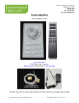
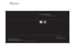
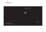
2 colors
PANTONE BLACK M
PANTONE 400 M
Discontinued
USER MANUAL
LIGHT-DRIVE RGB
Please check for the latest updates and changes on the TRAXON website.
© TRAXON TECHNOLOGIES ALL RIGHTS RESERVED.
WWW.TRAXONTECHNOLOGIES.COM
HONG KONG
NEW YORK
PARIS
TOKYO
RIO DE JANEIRO
FRANKFURT
MELBOURNE
SHANGHAI
BIRMINGHAM
ROTTERDAM
Manual - Version 1.0
1 colors
PANTONE BLACK M
Discontinued
USER MANUAL
1. INTRODUCTION: P1-2
2. CONTENTS: P3
3. INSTALLATION: P4-5
4. SYSTEM CONFIGURATION: P6-7
5. FUNCTION: P8-12
6. DIP-SWITCH SETTINGS: P12-15
7. IR REMOTE CONTROL: P16
8. ELECTRONICS: P17
9. CARE AND MAINTENANCE: P18
10. WARRANTY STATEMENT: P18
1 colors
PANTONE BLACK M
1. INTRODUCTION
Discontinued
1.1 SAFETY INSTRUCTION
LIGHT DRIVE RGB SC.CD.5000000 (BLACK)
LIGHT DRIVE RGB SC.CD.5000100 (WHITE)
FOR YOUR OWN SAFETY AND THAT OF THE PRODUCT, PLEASE READ THIS
USER MANUAL CAREFULLY BEFORE BEGINNING SET-UP AND INSTALLATION!
The wall mount unit is a standalone DMX controller for RGB LED fixtures. The device provides direct
access to connected DMX devices enabling control of color and brightness. Memory slots allow
WARNING
color presets. A sequence and i-wash mode offer dynamic scene playback.
The device comes with a sophisticated user interface providing colored keys as well as a jog dial for
setting values.
The device is designed as a plug & play unit (no configuration needed).
3.
4.
Do not touch any printed circuit board without suitable hand protection.
9.
In the event of serious operating problems, stop using the unit immediately.
•
The switch box installation should be performed carefully.
•
Always use spare parts identical to those of the original unit.
•
Do not touch any wire during operation as high voltage may cause electric shock.
CAUTION
8.
1.
Light-Drive cover
2.
Function buttons (Color, Brightness, Speed, Play/
•
Keep the outer case of the fixture clean with a soft cloth.
•
Audio/Visual such as television and radio may interfere with the device performance. Keep in
mind not to use such devices in close proximity to the unit.
•
There are no parts which are intended to be serviced or maintained by the user. Do not attempt
any repairs without the assistance of a trained professional. In the event your unit may require
service, please contact your nearest dealer.
Pause)
3.
Jog dial / ON-OFF switch
4.
Proximity sensor
5.
IR sensor
6.
Function buttons (Memory slots m1-m6, Zone1, Zone2,
The maximum ambient temperature is 40°C.
•
7.
5.
6.
6aa0
82mm/3.23”
14mm/0.55”
170mm/6.70”
9.
46mm/1.81” 19.85mm/0.78”
Unpack and check carefully that there is no transportation damage before using the unit.
•
•
74mm/2.92”
2.
2mm/0.08”
13mm/0.51”
60.3mm/2.37”
55mm/2.17”
1.
45mm/1.77”
14.5mm/0.57”
17.5mm/0.69”
100mm/3.94”
•
ZoneX, Sequence Function, White Mode, iWash
Function)
1
7.
DIP switch
8.
Output 1
9.
Output 2
2
1 colors
PANTONE BLACK M
2. CONTENTS
Discontinued
3. INSTALLATION
LIGHT-DRIVE RGB (SC.CD.5000000) BLACK
LIGHT-DRIVE RGB (SC.CD.5000100) WHITE
The Light-Drive unit installs easily and quickly with the use of a switch box (optional). The base
plate of the Light-Drive has preset mounting holes for international switch box dimensions.
2 X TX Connect Data Cable (DMX)
4 X Mounting Screws
1 X Light-Drive RGB
1. Carefully seperate the Light-Drive cover and base
2. Set position of swtich box (optional)
3. Mount Light-Drive base with appropriate screws
4. Connect output cables and click Light-Drive
cover back into place
3
4
1 colors
PANTONE BLACK M
Discontinued
4. SYSTEM CONFIGURATION
4-1. TX Connect
TX Connect is an easy and user friendly plug’n’play connection system for TRAXON products.
Connection Accessories
A
1. Switch box depth (A) must be at least 35mm/1.38” to install.
Please check your local swtich box size before installation.
2. Light Drive unit supports UK, EU, USA, and JP standard switch box dimensions.
3. The switch box installation should be performed carefully.
TX CONNECT Smart
Data (DMX) Cable
0.2m
DI.IC.0020000
1m
DI.IC.0100000
3m
DI.IC.0300000
5m
DI.IC.0500000
10m
DI.IC.1000000
20m
DI.IC.2000000
TX CONNECT Smart
Interconnection Cable
AC Power Cable,2m
8cm
TI.IC.0008000
EU PS.AC.0000100
30cm TI.IC.0030000
US PS.AC.0000200
60cm TI.IC.0060000
UK PS.AC.0000300
AU PS.AC.0000400
JP
PS.AC.0000500
4. Be careful to avoid touching the PCB with a bare hand.
5. DO NOT power up the unit until all installation steps are completed.
5
TX CONNECT Smart
Power/Data Injector Box
TX CONNECT Smart
Data Extractor Box
LED Engine Smart
100W Indoor
TI.ZI.0000100
TI.DO.0000100
PS.IA.0010000
6
1 colors
PANTONE BLACK M
Discontinued
4-2. System Diagram
DMX address chart of each output (Refer page1. Output)
case:1 Connect fixtures with both output
Output 2
1
Output 1
OUTPUT:1
Zone 1: TX Connect Smart (Example)
257
OUTPUT:2
TX Connect Smart
Inter connection Cable
LED Engine Smart
512
Zone 2
case:2 Use Zone X extension*
TX Connect Smart
Injector Box
1PXL Fixture
512
Zone 2
90-240VAC
1
* Maximum 85 1PXL fixtures / Zone
TX Connect Smart
Data (DMX) Cable
256 257
Zone 1
1PXL Fixture
1PXL Fixture
OUTPUT:1
256 257
Zone 1
257
OUTPUT:2
512
Zone 2
512
Zone X
* Zone X is future extension for access to TRAXON micro server ll. (Q4/2008)
*Additional LED Engine Smart PSUs and DMX Booster units ( DI.AC. 0200100) may be required, depending on installation configuration.
* Please refer to TX Connect System Manual and Product Specifications for full details.
* i-WASH MODE can operate a maximum of 31 segments. (Refer to illustration 2 page 14)
5. FUNCTIONS
Zone 2: TX Connect XB (Example)
AC Input
LED Engine XB
Wall Washer XB -36
Wall Washer XB -36
Wall Washer XB -36
COLOR
Daisy-chain to
LED Engine XB
SPEED
TX Connect XB
Liner XB -18
BRIGHTNESS
JOGWHEEL:
POWER ON/OFF
COLOR PREVIEW
Liner XB -18
PLAY/PAUSE
TX Connect XB
Splitter
Max. 36 LEDs
per output
APPROXIMITY SENSOR
IR RECEIVER
MEMORY SYMBOLS
The number of outputs per LED Engine XB depends on ther Rated Power and model used.
MEMORY KEYS
Note: The above shown configurations are examples only. The Light-Drive can be used with any 1PXL RGB lighting
ZONE SELECTION KEYS
fixture (Module, Board, Cove Light, Strip).In the case of applications using XB line fixtures only ( Wall Washer XB,
Liner XB, Nano Liner XB, Spot XB) use the new series LED Engine XB ( PX.IC.xxxxxxx/PX.ID.xxxxxxx ) available Q4,
2008. Please refer to your local Traxon dealer for more details.
7
SEQUENCE FUNCTION
I-WASH FUNCTION
WHITE MODE
8
1 colors
PANTONE BLACK M
5-1. JOG/NAVIGATION
•
Pushing the Jog-wheel activates/deactivates the unit.
•
By default the Jog wheel modifies the BRIGHTNESS of the selected zone. Turning the wheel
•
5-2.1 MEMORY MODE
clockwise, increases the intensity and vice versa. (The Jog-wheel is back lit with RGB LEDs.)
Press M1-M6 to save and recall color settings in selected zone (from any other mode, press
When the unit is set to BRIGHTNESS MODE, the Jog back light is white. The unit
any memory key for 1 second to go into MEMORY MODE).
automatically switches to this mode after being idle for 10 seconds.
•
Discontinued
5-2 MODES
Brightness: • Turn Jog-wheel to increase /decrease brightness.
Pressing the COLOR button activates COLOR MODE. The Jog-wheel back light synchronizes
• Press Brightness for 2 seconds to set brightness to 100%.
with current color output of selected zone.
• Press M1-M6 for 2 seconds to save current color setting to memory (short
•
By turning the Jog-wheel you can select any RGB color.
•
The SPEED button is only active during playback in SEQUENCE/i-WASH function.
•
During playback in SEQUENCE or i-WASH function, playback can be paused or continued
• Jog-wheel back light displays output color.
by pressing the PLAY/PAUSE button.
• Press M1-M6 for 2 seconds to save current color setting to memory (short
•
•
beep confirms saving).
Color:
During all other modes, the unit switches to SEQUENCE function by pressing the
• Turn jog-wheel to change color.
beep confirms saving).
PLAY/PAUSE button.
Speed:
The LED display of the MEMORY buttons indicate the current speed as a “bar graph”: No
Play/Pause • Unit enters SEQUENCE function
• N/A
LEDs ON - slowest replay speed, all LEDs ON - fastest replay speed.
•
All buttons are equipped with LED backlight. These are activated by a proximity sensor. In
idle mode, they will automatically turn off after 5 seconds, the Jog-wheel after 10 seconds.
5-2.2 SEQUENCE FUNCTION
Press the Sequence button to activate SEQUENCE function in the selected zone.
Brightness: • Turn Jog-wheel to increase /decrease brightness.
• Press Brightness for 2 seconds to set brightness to 100%.
Color:
• Unit enters COLOR MODE
Speed:
• Turn Jog-wheel to increase /decrease speed.
• Memory symbols show the speed as a “bar graph”
Play/Pause • Pauses the current replay (Play/Pause is blinking)
9
10
1 colors
PANTONE BLACK M
Discontinued
5-2.3 WHITE FUNCTION
5-2.6 IDLE MODE
Press the WHITE button to activate WHITE MODE in the selected zone.
After 10 seconds without interaction, the unit goes into Idle-Mode automatically.
• All LED backlight turn off.
Brightness: • Turn Jog-wheel to increase / decrease brightness.
• All active Sequence/i-Wash modes keep running. ( If the Proximity Sensor
• Press Brightness for 2 seconds to set brightness to 100%.
Color:
• Turn Jog-wheel to fade between Warm White and Cold White.
registers any activity, the unit will automatically enter the last active
Speed:
• N/A
mode.)
Play/Pause • Unit enters SEQUENCE function
5-2.7 SPECIAL FUNCTIONS
5-2.4 i-WASH FUNCTION
Press the i-Wash button to activate iWash function (soft fade on the outer color circle range
Press Zone 1 and Zone 2 button simultaneously and hold for 2 seconds to copy all memory
setting (M1-M6) of Zone 1 into Zone 2 (short beep confirms saving).
[RGB]) in the selected zone. In Zone 1 the devices replays the color fade sequentially over
several devices (see point.6).
Brightness: • Turn Jog-wheel to increase / decrease brightness.
6. DIP-SWITCH SETTINGS
• Press Brightness for 2 seconds to set brightness to 100%.
Color:
• Unit enters COLOR MODE
Speed:
• Turn Jog-wheel to increase / decrease speed.
6-1. DIP OVERVIEW
• Memory symbols show the speed as a “bar graph”
Play/Pause • Pauses the current iWash replay (Play/Pause is blinking)
7
8
The unit comes with an 8-Dip switch on the backside.
5
3
Zone 2: • Controls 256 DMX channels on output 2
ON
Zone 1: • Controls 256 DMX channels on output 1
Switch 3
Future enhancement (Zone X)
2
the specified zone. Each Zone button has a LED back-light to mark the currently selected zones.
Switch 4-8 Binary selection of number of RGB unit in
Zone 1 (Refer to the Dip switch table)
Switch 2
Memory Lock Switch
1
This unit offers access to three different zones. By pressing the Zone buttons you can access
4
6
5-2.5 ZONE 1 / ZONE 2 / ZONE X
Switch 1
Com Port Switch
Zone X: • This button gives access to an external server via e:bus (Function available
Q4/2008, refer to your Traxon Partner for further information.)
11
12
1 colors
PANTONE BLACK M
6-2. MEMORY LOCK SWITCH
Discontinued
Illustration 2
A memory lock switch on the backside of the unit disables any user change of memory slot
presets.
Segment 1
Segment 2
6-3. SETTING NUMBER OF DEVICES IN ZONE 1
The DIP switch settings allows you to set the number of fixtures/light segments for the
Auto Addressing (ON/OFF)
DMX channel
dynamic iWash function in Zone 1 (See table below).
OFF
OFF
ON
OFF
ON
ch.1-3
ch.1-3
ch.1-3
ch.4-6
ch.4-6
The Light-Drive will address the first 31 sets of RGB channels (93 DMX channels), i.e. if all
- Maximum 85pcs 1PXL fixtures
fixtures are set to Auto-Addressing ON, the iWash function will be displayed on the first 31
fixtures only (Illustration 1). In order to set the light segments for the iWash function, please
set the fixtures that are to follow one segment to Auto-Addressing OFF (Illustration 2).
DIPSWITCH
Illustration 1
# Fixtures / Light Segments
Segment 1
Auto Addressing (ON/OFF)
DMX channel
Segment 2
Segment 3
Segment 31
ON
ON
ON
ON
ch.1-3
ch.4-6
ch.7-9
ch.91-93
- Maximum 85pcs 1PXL fixtures
13
4
5
6
7
8
All
0
0
0
0
0
1
1
0
0
0
0
2
0
1
0
0
0
3
1
1
0
0
0
4
0
0
1
0
0
5
1
0
1
0
0
6
0
1
1
0
0
7
1
1
1
0
0
8
0
0
0
1
0
9
1
0
0
1
0
10
0
1
0
1
0
11
1
1
0
1
0
12
0
0
1
1
0
13
1
0
1
1
0
14
0
1
1
1
0
14
1 colors
PANTONE BLACK M
7. IR REMOTE CONTROL
DIPSWITCH
4
5
6
7
8
15
# Fixtures / Light Segments
1
1
1
1
0
16
0
0
0
0
1
17
1
0
0
0
1
18
0
1
0
0
1
19
1
1
0
0
1
20
0
0
1
0
1
21
1
0
1
0
1
22
0
1
1
0
1
23
1
1
1
0
1
24
0
0
0
1
1
25
1
0
0
1
1
26
0
1
0
1
1
27
1
1
0
1
1
28
0
0
1
1
1
29
1
0
1
1
1
30
0
1
1
1
1
31
1
1
1
1
1
(SC.AC.0100100)
The IR Sensor is able to receive IR signals from the dedicated Light-Drive Infrared
Controller. The remote control activates and recalls all functions on the Light-Drive. (Except
storing color settings on m1-m6 and zone1 to zone 2 copying.)
197.4mm/7.77”
42.3mm/1.67”
15
Discontinued
23mm/0.91”
16
1 colors
PANTONE BLACK M
8. ELECTRONICS
9. CARE AND MAINTENANCE
8-1. PIN ASSIGNMENT OF OUTPUT CONNECTORS
The PIN assignment of the two DMX outputs (female RJ45 ports) is as follows:
Traxon™ products are of superior design and quality and should be treated with
care. The recommendations below will help fulfill warranty obligations and gain
maintain a quality product.
The unit is powered by an external PSU running at 24 VDC. Power is only supplied via RJ45
- Make sure that the power is switched off before installation and/or maintenance
- Make sure that the products are installed correctly and securely
- For indoor use only
- Keep products in a dry and precipitation free area as this may damage the products’
electronics.
- Keep products in a dirt and dust free environment
- Make sure the products are not exposed to extreme heat and that they have sufficient
airflow and cool air circulation if required
- Do not attempt to service or repair the products unless done by an authorized service
personnel. Contact the local Traxon office or distributor for details
- Do not drop, knock or shake the products as rough handling may damage the
electronics and void the warranty
- Do not use harsh chemicals, cleaning solvents or strong detergents to clean. Wipe with
a damp cloth on housings and a dry cloth on electronics to remove dirt or dust.
pins. Both RJ45 Plugs provide blocking diodes against cross-current of different levels.
If the products are not working correctly, please contact your nearest authorized service centre or
8
1
1
DMX -
2
DMX +
3
GND
4
Power GND
5
Power +24VDC
6
GND
7
No function
8
No function
8-2. POWER SUPPLY
8-3. TECHNICAL SPECIFICATIONS
17
Discontinued
Dimension:
Weight:
Operating Voltage:
100mm x 170mm x 45mm / 3.93” x 6.69” x 1.77”
120g / 0.26lbs
24VDC
Current Consumption:
60mA
Power Consumption:
1.5 Watt
Remote controllable:
Yes
Operating Temperature:
0 C ~ + 50 C ( +32 F ~ +122 F)
Environment:
Indoor
Traxon office for assistane.
10. WARRANTY STATEMENT
Traxon warrants its Products against material or workmanship defects for a period of two (2)
years from date of purchase, provided that the purchased items are used under the conditions
stated in this user manuals.
Please refer to the Product Warranty section under www.traxontechnologies.com/terms for
warranty terms and conditions.
18