1
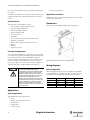
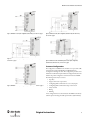
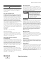
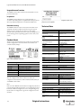
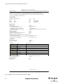
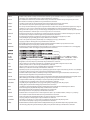
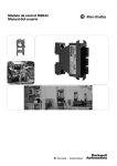
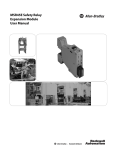
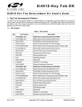
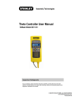
MSR42 Control Module
User Manual
Important User Information
Because of the variety of uses for the products described in this publication, those responsible for the
application and use of this control equipment must satisfy themselves that all necessary steps have been
taken to assure that each application and use meets all performance and safety requirements, including
any applicable laws, regulations, codes and standards.
The illustrations, charts, sample programs and layout examples shown in the guide are intended solely for
purposes of example. Since there are many variables and requirements associated with any particular
installation, Rockwell Automation does not assume responsibility or liability (to include intellectual property
liability) for actual use based upon the examples shown in this publication.
Rockwell Automation publication SGI-1.1, Safety Guidelines for the Application, Installation and
Maintenance of Solid-State Control (available from your local Rockwell Automation sales office), describes
some important differences between solid-state equipment and electromechanical devices that should be
taken into consideration when applying products such as those described in this publication.
Reproduction of the contents of this copyrighted publication, in whole or part, without written permission
of Rockwell Automation, is prohibited.
Throughout this manual we use notes to make you aware of safety considerations:
WARNING
IMPORTANT
ATTENTION
Identifies information about practices or circumstances that can cause an explosion in
a hazardous environment, which may lead to personal injury or death, property
damage, or economic loss.
Identifies information that is critical for successful application and understanding of
the product.
Identifies information about practices or circumstances that can lead to personal
injury or death, property damage, or economic loss. Attentions help you identify a
hazard, avoid a hazard, and recognize the consequences.
SHOCK HAZARD
Labels may be on or inside the equipment (for example, drive or motor) to alert people
that dangerous voltage may be present.
BURN HAZARD
Labels may be on or inside the equipment (for example, drive or motor) to alert people
that surfaces may reach dangerous temperatures.
It is recommended that you save this user manual for future use.
MSR42 Control Module User Manual
Content
Technical Data . . . . . . . . . . . . . . . . . . . . . . . . . . . . . . . . . . .12
Approvals and Conformity . . . . . . . . . . . . . . . . . . . . . . . . . 1
Appendix . . . . . . . . . . . . . . . . . . . . . . . . . . . . . . . . . . . . . . . .13
Interrupt Ignore Time . . . . . . . . . . . . . . . . . . . . . . . . . . . . . . . . . . . . . . 13
Introduction . . . . . . . . . . . . . . . . . . . . . . . . . . . . . . . . . . . . . . 1
Special features . . . . . . . . . . . . . . . . . . . . . . . . . . . . . . . . . . . . . . . . . . . . . . 2
Customer Configurations . . . . . . . . . . . . . . . . . . . . . . . . . . . . . . . . . . . . 2
Applications . . . . . . . . . . . . . . . . . . . . . . . . . . . . . . . . . . . . . . 2
Typical applications . . . . . . . . . . . . . . . . . . . . . . . . . . . . . . . . . . . . . . . . . . 2
Application restrictions . . . . . . . . . . . . . . . . . . . . . . . . . . . . . . . . . . . . . . 2
Dimensions . . . . . . . . . . . . . . . . . . . . . . . . . . . . . . . . . . . . . . . 2
EC Declaration of Conformity . . . . . . . . . . . . . . . . . . . . . .15
Approvals and Conformity
The CE-declaration as well as the safety approval, performed by TÜV
Rheinland GmbH are available online at www.ab.com. The actual list of
relevant safety data and applied standards is given in these documents.
Wiring diagrams . . . . . . . . . . . . . . . . . . . . . . . . . . . . . . . . . . 2
MSR42 units can only achieve their
function as a safety control module, if the
instructions in these manual and
accompanying documents are followed
and all laws and regulations are observed
at the time of installation.
Should these instructions not be carefully
followed, serious injury or death may
occur. The installer or system integrator
has full responsibility for a safe
integration of this product.
This instruction manual is part of the
MSR45E expander module. It must be
kept accessible together with the other
machine documentation during its entire
life cycle for all personnel responsible for
assembly, installation, operation and
maintenance.
Basic configuration . . . . . . . . . . . . . . . . . . . . . . . . . . . . . . . . . . . . . . . . . . 2
Customer Configurations . . . . . . . . . . . . . . . . . . . . . . . . . . . . . . . . . . . . 3
Status outputs . . . . . . . . . . . . . . . . . . . . . . . . . . . . . . . . . . . . 4
LED display elements . . . . . . . . . . . . . . . . . . . . . . . . . . . . . . 4
Response time . . . . . . . . . . . . . . . . . . . . . . . . . . . . . . . . . . . . 4
General . . . . . . . . . . . . . . . . . . . . . . . . . . . . . . . . . . . . . . . . . . . . . . . . . . . . . 4
Micro 400 safety light curtain . . . . . . . . . . . . . . . . . . . . . . . . . . . . . . . . 5
Other safety components connected to GPIO terminals . . . . . . . . 5
MSR45E relay expansion module . . . . . . . . . . . . . . . . . . . . . . . . . . . . . 5
Basic configuration . . . . . . . . . . . . . . . . . . . . . . . . . . . . . . . . . . . . . . . . . . 5
Installation . . . . . . . . . . . . . . . . . . . . . . . . . . . . . . . . . . . . . . . 5
Mounting location . . . . . . . . . . . . . . . . . . . . . . . . . . . . . . . . . . . . . . . . . . . 5
Cable and wires . . . . . . . . . . . . . . . . . . . . . . . . . . . . . . . . . . . . . . . . . . . . . 5
Supply voltage . . . . . . . . . . . . . . . . . . . . . . . . . . . . . . . . . . . . . . . . . . . . . . . 5
Earth connection . . . . . . . . . . . . . . . . . . . . . . . . . . . . . . . . . . . . . . . . . . . . 6
Micro400 light curtain . . . . . . . . . . . . . . . . . . . . . . . . . . . . . . . . . . . . . . . 6
Start mode . . . . . . . . . . . . . . . . . . . . . . . . . . . . . . . . . . . . . . . . . . . . . . . . . . 6
Minimum off time . . . . . . . . . . . . . . . . . . . . . . . . . . . . . . . . . . . . . . . . . . . 6
EDM or start release . . . . . . . . . . . . . . . . . . . . . . . . . . . . . . . . . . . . . . . . . 6
Safety Components . . . . . . . . . . . . . . . . . . . . . . . . . . . . . . . . . . . . . . . . . . 7
Safety Override . . . . . . . . . . . . . . . . . . . . . . . . . . . . . . . . . . . . . . . . . . . . . . 7
OSSD connections . . . . . . . . . . . . . . . . . . . . . . . . . . . . . . . . . . . . . . . . . . 8
Muting . . . . . . . . . . . . . . . . . . . . . . . . . . . . . . . . . . . . . . . . . . . . . . . . . . . . . 8
Blanking . . . . . . . . . . . . . . . . . . . . . . . . . . . . . . . . . . . . . . . . . . . . . . . . . . . . 8
Blanking Teach-In . . . . . . . . . . . . . . . . . . . . . . . . . . . . . . . . . . . . . . . . . . . 9
Single Scan Filter . . . . . . . . . . . . . . . . . . . . . . . . . . . . . . . . . . . . . . . . . . . . 9
Testing the MSR42 . . . . . . . . . . . . . . . . . . . . . . . . . . . . . . . . . . . . . . . . . . 9
Introduction
The MSR4x is a family of extremely compact safety controller modules.
The main controlling module allows for the connection and control of
the compact Allen-Bradley GuardShield Micro400 safety light curtain.
Depending on the configuration, other safety components can also be
connected and monitored simultaneously.
Diagnostic . . . . . . . . . . . . . . . . . . . . . . . . . . . . . . . . . . . . . . .10
External faults . . . . . . . . . . . . . . . . . . . . . . . . . . . . . . . . . . . . . . . . . . . . . . 10
Internal faults . . . . . . . . . . . . . . . . . . . . . . . . . . . . . . . . . . . . . . . . . . . . . . 10
Expansion modules
Selection tables . . . . . . . . . . . . . . . . . . . . . . . . . . . . . . . . . .11
Main module
Accessories / Components . . . . . . . . . . . . . . . . . . . . . . . .11
Inspection and service . . . . . . . . . . . . . . . . . . . . . . . . . . . .12
Inspections . . . . . . . . . . . . . . . . . . . . . . . . . . . . . . . . . . . . . . . . . . . . . . . . . 12
Decommissioning . . . . . . . . . . . . . . . . . . . . . . . . . . . . . . . . . . . . . . . . . . 12
Product labels . . . . . . . . . . . . . . . . . . . . . . . . . . . . . . . . . . .12
Figure 1: MSR42 controller with some safety components which can be connected
(depending on individual configuration)
Either the MSR41 or 42 offers two safety PNP outputs. Extension
modules are available for applications which need relay contact outputs.
Original instructions
1
Light Curtain Multi-Function Control Module User Manual
Up to three expander modules can be easy attached & controlled by the
base module.
In addition to the multifunction controllers, models are offered in special
configurations which are described in the appendix at the end of this
manual.
Special features
The characteristics of the MSR42 base module:
• Category 4, PLe according to EN ISO 13849-1
• Type 4 according to EN61496-1 / -2
• SIL CL3 according to EN62061
• SIL3 based on IEC 61508
• Short response times
• Expandable
• Up to 3 safety relay expander modules per base module
• Adjustable stop delay time
• Different safety components suitable for connection
• Blanking
• Muting
• Single scan selectable
• Automatic storage facilities
Application restrictions
MSR42 base modules are not intended for application in explosive (EX)
or in radioactive environments.
Dimensions
The dimensions of the MSR42 housing are illustrated in Figure 2.
Customer Configurations
The configuration of a MSR42 base module may very easily be adapted
to the customer requirements of an individual application with the help
of the USB/optical interface and the Allen-Bradley Guardmaster
Software “Configuration & Diagnostic Tool”. More information can be
found in the Software Technical Manual. The software is capable of
generating a configuration control document which lists configurations
and specifications of the controller and light curtain (Figure 16).
The resolution and the response time may
increase due downloading other
configuration settings for the Micro 400
and other safety sensors connected to
MSR42. Consider the relevant resolution
and the maximum response time when
evaluating the safety distance. See
Chapter 7. All relevant data of the actual
configuration are always described in the
actual configuration control document
for that controller. Make sure that the
actual document is always stored near to
the control unit.
Figure 2: Base module dimensions are the same for expansion modules
Wiring diagrams
Basic configuration
The following figures show the connection possibilities for the MSR42
base module with the basic configuration. The logic of this basic version
is exemplified in the accompanying configuration control document:
Figure
Safety component
Start mode
Start release
Figure 3
Micro400
manual
no
Figure 4
Micro400
manual
yes
Figure 5
Micro400
automatic
no
Figure 6
Micro400
automatic
yes
Applications
Typical applications
Typical MSR42 base module applications are:
• Presses
• Robotic cells with automatic insertion
• Assembly lines
• Indexing tables
• Conveyor systems
2
Original instructions
MSR42 Control Module User Manual
Figure 3: MSR42 base module (basic configuration, manual start) ). For teach-in see page 8
Figure 4: MSR42 base module (basic configuration, manual start, with start release).
For teach-in see page 8
Figure 6: MSR42 base module (basic configuration, automatic start, with start release).
For teach-in see page 8
Figure 7: MSR42 base module and MSR45E expander module (basic configuration,
automatic start, with start release). For teach-in see page 8
Customer Configurations
The configuration of a MSR42 control module is set up via of the USB/
optical interface and the Allen-Bradley GuardShield Software
“Configuration & Diagnostic Tool”. The configuration procedure can be
found in the Technical Description Manual. Configuration details can be
found in the specific configuration control document for the MSR42.
Figure 5: MSR42 base module (basic configuration, automatic start). For teach-in see page 8
The following features may be selected:
• Stop delay
• Single scan for faster response times
• Configuring GPIO terminals for one or two safety inputs
• Configuring GPIO terminals for E-Stop or door switch
• Safety Override
• Muting
• Blanking
A new configuration has to be downloaded to the MSR42 controller by
authorized personnel using the USB/optical interface (445L-AF6150).
Original instructions
3
Light Curtain Multi-Function Control Module User Manual
LED
If authorized personnel reconfigure the
control module using the USB/optical
interface, then depending on the
configuration the response time or the
stop delay time t(delay) may increase. So
it is very important that after every new
configuration.
a. the configuration change label
(page 13) is placed on the control
module and
b. the new response time is confirmed to
be within the limits given by the risk
analysis of the machine and
c. All relevant data of the actual
configuration are always described in
the actual configuration control
document for that controller. Make
sure that the actual document is
always stored near to the control unit.
d. Using the blanking mode, the
resolution of the Micro 400 will be
reduced. Label the Micro 400 with the
new resolution. A label is supplied
with the Micro 400 light curtain
mounting kit.
Signal / Color /Status
Signal / Color /Status
Lamp
Orange / muting or blanking Off / muting or blanking not
activated
activated
GPIO4
+24 V / green / automatic
start
GPIO3
+24 V / green / manual start
0 V / off / manual start
signal high or automatic start
GPIO2
+24 V / green / Teach-in
Blanking active
0 V / off / Teach-in Blanking
inactive
GPIO1
+24 V / green / Teach-in
Blanking active
0 V / off / Teach-in Blanking
inactive
OSSD2
+24 V / green / Micro 400 not 0 V / red / Micro 400 activated
Activated
(e.g. interrupted)
OSSD1
+24 V / green / Micro 400 not 0 V / red / Micro 400 activated
Activated
(e.g. interrupted)
Info2 (LED)
See page 4
See page 4
Info1 (LED)
See page 4
See page 4
IN2
+24 V / green / start release 0 V / red / no start release
okay
signal
IN 1
+24 V / green / no test
0 V / red / test
0V
-
-
+24 V
+24 V / green / power
connected
0 V / off / no power
connected
0 V / off / manual start
Table 2
Status outputs
The MSR42 base module has two status outputs (“Info1” and “Info2”).
The logic of these two outputs depends on the configuration. A
description of these outputs is given in the configuration control
document. The following table shows the logic of the two status outputs
for the basic configuration. The state of the status outputs will also be
displayed through LED, visible on the front side of the main module.
Terminal (LED)
Output "high" (+24 V)
Output "low" (0 V)
Info1 (LED)
Start ok (green)
No start possible (red)
Info2 (LED)
System okay (green)
Error (Lock out) (red)
Table 1
These outputs may not perform any
safety relevant functions. They are
diagnostic outputs which provide status
to a machine controller.
Response time
General
The response time of a MSR42 main module depends on the
configuration.
The relevant maximum response times for the MSR42 control module,
with respect to a specific Micro 400 light curtain and MSR45E expander
module, as well as a specific safety component may be calculated using
the formulas below.
The response time may be increased if a stop delay time t(delay) is
configured for a safety component or a Micro 400 light curtain. During
this delay, all start impulses are ignored. The safety outputs will switch
off at the end of this delay period.
The controller is shipped with the double scan filter. Single scan filter can
be selected to reduce the response time. The relevant times may be found
in the corresponding configuration control document (e.g. see
configuration software manual).
LED display elements
Terminology
Table 2 gives information about the LED on the front side of a MSR42
control unit with the basic configuration:
t(C)
4
Response time for the MSR42 control module (evaluation time),
without light curtain evaluation time
t(LC)
Response time of the light curtain
t(delay)
Stop delay time for the outputs
t(em)
Response time for the MSR45E expansion module
t(GPIO)
Evaluation time for the safety component (GPIO filter time)
t(SCext)
Response time of the external safety component (e.g. Safe4)
t(totLCOSSD)
Maximum OSSD response time triggered by the light curtain
t(totLCEXT)
Maximum relay extension module response time for the light curtain
t(totSCOSSD)
Maximum OSSD response time for the safety components on GPIO
Original instructions
MSR42 Control Module User Manual
Basic configuration
Terminology
t(totSCEXT)
Maximum relay extension module response time for the safety
components on GPIO
Table 3
The response time of the device under a specific configuration can be
found in the configuration control document (see configuration
software manual)
The maximum controller response time t(C) for the MSR42 control
module is given in chapter 14 However, depending from the connected
Micro 400 light curtain, the response time may be faster. The exact value
can be read out from the configuration control document, created with
the Configuration & Diagnostic Tool software.
If authorized personnel reconfigure the
controller using the USB/optical Interface
(445L-AF6150), then depending on the
configuration the response times may be
increased. So it is very important that
after every new configuration to proceed
according chapter “Customer
Configurations” on page 3.
Micro 400 safety light curtain
The light curtain response time t(LC) is a part of the response time for
the OSSD outputs. The label of the Micro 400 shows the worst case
response time which occurs when the MSR42 runs active double scan
filter (default). Using a single scan yields a faster response time but this
makes the light curtain more vulnerable to ambient light. The light
curtain response time t(LC) with the double scan filter can be found in
the Micro 400 manual and with/without double scan filter in the
configuration control document (see configuration software manual).
The configuration control document gets generated by the MSR42
Software “Configuration & Diagnostic Tool”. Therefore the light curtain
resolution and protective field height has to be entered.
Installation
t(totLCOSSD) = t(C) + t(LC) + t(delay)
For proper installation and connection, please consult the relevant laws
and regulations. The safety officer of the manufacturing facilities, the
local authorities (OSHA in USA, HSE in GB) or the respective industry
associations are available for any safety related queries. The requirements
of the safety regulations of electrical engineering, the local employer’s
liability insurance association and the international standard IEC 60204
are to be taken into full consideration. In the following chapters the
installation of all possible safety components, which can in general be
connected to a MSR42 control module, is also described. Which safety
component has to be connected to guarantee a faultless function is
printed in the corresponding configuration control document for the
MSR42 control module.
Output relay extension module
Mounting location
The response time for the MSR45E expansion module (relay safety
output) with respect to the Micro 400 light curtain is the sum of the
OSSD response time and the response time of the extension module.
The MSR42 control modules must be mounted in a control cabinet
which is sealed to at least IP54. The units must be snapped onto a 35 mm
mounting rail, which is grounded. If it is used outside of a control cabinet
housing with a protection category of IP54 and a mounting rail
capability is recommend.
The response time for the MSR42 main module (OSSD safety outputs)
with respect to the Micro 400 light curtain t(totLCOSSD) is the sum of
the controller response time t(C) + the response time of the light curtain
t(LC) + ,the stop delay time t(delay) (if a delay is configured and selected
for the Micro 400).
Output OSSD
t(totLCEXT) = t(totLCOSSD) + t(em)
Other safety components connected
to GPIO terminals
Cable and wires
The response time of the MSR42 control module OSSD safety outputs
with respect to the safety components connected to the GPIO terminals
is the sum of the controller response time and the response time of the
Micro 400 light curtain, the safety component evaluation time, the
response time of the external connected safety components and the stop
delay time (if delay is configured and selected for the safety components).
The wires from the MSR42 control module must be securely separated
and guided away from the wires of the relay section (MSR45E expander
module). In the case of high EMC levels shielded cables may be required
to preserve signal integrity.
t(totSCOSSD) = t(C) + t(LC) + t(GPIO) + t(SCext) + t(delay)
To safeguard the controller, the +24 V terminal should be protected with
an external 5 A fuse. The controller and the machine should be off-line
before beginning the installation. The supply voltage must conform to
the requirements of EN 60204-1, it must bridge a 20 ms interruption of
the supply network. When considering the supply voltage, it must be one
of the following: SELV (Safety-Extra-Low-Voltage) or PELV (ProtectiveExtra-Low-Voltage) in accordance with IEC 364-4-41.
MSR45E relay expansion module
The response time for the MSR45E extension module (safety relay
output) with respect to the safety components connected on the GPIO
terminals t(totSCEXT) is the sum of the main module response time
t(totSCOSSD) + and the response time of the extension module t(em).
Supply voltage
t(totSCEXT) = t(totSCOSSD) + t(em)
Original instructions
5
Light Curtain Multi-Function Control Module User Manual
Earth connection
According to EN 60204 article 9.2.4.4.2 a
system may not automatically restart,
even after the cause of the shutdown has
been eliminated and thereby another
danger may still exist to the operator. If
the MSR42 control module is configured
with an “automatic start”, this
requirement must be fulfilled by further
measures.
The earth of each MSR42 control module is realized through the
connection to the mounting rail. Consequently it is important to ensure,
that the mounting rail has a good earth connection.
Micro400 light curtain
The two RJ45 sockets on the lower portion of the control module are for
the connection of Allen-Bradley GuardShield Micro400 (white = E =
emitter; blue = R = receiver). To help protect the RJ45 connectors the
cables have to be snapped into the provided cable holders at the.MSR42
housing.
Start mode
The MSR42 can be configured to have the following start modes:
• automatic start or
• manual start.
In case of the basic configuration the start mode can also be configured
without the configuration software. By connecting +24V to GPI03 and
GPI04, automatic reset is enabled (see wiring diagrams).
Manual start
When all of the inputs of the safety system have a safe signal, depressing
the start button will cause the two safety OSSD outputs to change from
low to high. If a MSR45E relay expander module is connected, it will
close. If more than one safety component is configured, then all
components must have safe signals to all inputs before a start is allowed.
The start button is monitored to prevent an unintentional start. Pulse
length must be between: 50 ms and 5 sec. If the start impulse is longer or
shorter, the start input will be ignored by the device. The configuration
control document identifies which terminal the start button is connected
to. If the start button is connected to IN1or IN2 then a red LED
indicates that a start signal is present, a green LED indicates no signal is
present.
Terminal
LED green
LED red
IN 1 or IN 2
No start signal present
Start signal present (button pressed)
Table 4
It is fundamental that the start button be
mounted so that the danger area is clearly
visible. That is, when pressing the start
button it must be guaranteed that no one
is detained within the danger area.
Minimum off time
According to the standard IEC 61496-2 a safety light curtain must have a
minimum safety output off time of 80 ms. This means that even in the
case of a very short safety light curtain interruption, the safety outputs
will stay low (Relays = open) for 80ms at minimum. A start signal will
only be recognized after the 80ms duration.
EDM or start release
If an MSR42 is used with external relays or contactors, the contacts of
that device must be monitored. An example category 4 application has
two external contactors, each with force guided contacts must be
inserted. For monitoring the function of these contactors, each relay
block must have at least one normally closed contact which is fed back in
series to IN2 (or IN1 depending on configuration) of the MSR42
control module (e.g. Figure 4).
Two options are possible for this monitoring:
1. Start release: The signal at the corresponding input terminal must be
high before the start button is pressed (this means: the normally closed
contacts of the external relays must be closed before allowing a start). The
option “start release” is pre-configured in the MSR42 control module
(440R-P226AGS-NNR) (e.g. Figure 4).
2. EDM (external device monitoring): The input signal of the EDM
terminal is always monitored. This means: not only at the beginning
before a start the signal must be correct. Also after the start a signal
change must happen, otherwise an emergency stop occurs. If a high signal
is present for longer than 5 seconds, a lock-out will occur.
If the configuration control document shows that EDM or start release
must be attached to terminal IN 1 or IN 2, then the meaning of the
respective LED is shown below.
Terminal
LED green
LED red
EDM at IN 1 or IN 2
EDM signal okay
EDM signal wrong
Start release at IN 1 or
IN 2
Start release signal okay
Start release signal wrong
Warning: Important safety advice:
Table 5
Automatic start
The start release or EDM input is not cross-fault monitored and
therefore not a safety input.
If a safety component is configured for “automatic start”, then, after the
activation and the deactivation of the safety component, the two OSSD
outputs will change automatically from low to high again and if
connected the MSR45E expander relay contacts will automatically reclose.
6
Original instructions
MSR42 Control Module User Manual
1. In cases where the MSR42 control
module is installed without expander
modules the function external device
monitoring (EDM) or start release
must always be used, the only
exceptions are if the PNP outputs are
connected with another safety relay
or a safety PLC.
2. Through the use of start release or
EDM, it is possible to switch external
“power” contactors within the safety
circuit. Such contactors often deal
with large inductive loads, which
during the switching off phase can
create large potential peaks. For this
reason surge suppressors are highly
recommended. Surge suppressors
must be connected parallel to the
external contactors (e.g. Figure 4).
They may never be connected parallel
to the contacts of a MSR45E expander
module. Surge suppressors may
drastically increase the off delay time
of the contactors. Diodes are not
allowed to be used as surge
suppressors, for exactly this reason.
Figure 8: Connecting an emergency stop
In general the two circuits of dual channel safety components are crossfault monitored. A short of these two circuits would lead to an
emergency stop of the MSR42 control module. The two circuits are also
time monitored. This means, if one circuit changes e.g. of an emergency
stop, the second circuit has to follow within 5 seconds. If this is not the
case, the MSR42 interprets this as a fault and the controller switches off
the safety circuit.
Depending on the configuration and the application, there may be more
terminals than components needed. The unused ports may be bridged.
Shielded cables are recommended for bridging to reduce the input of
EMC.
Terminal
LED green
LED off
GPIO3
Contact GPIO1/GPIO3 closed
Contact GPIO1/GPIO3 open
GPIO4
Contact GPIO2/GPIO4 closed
Contact GPIO2/GPIO4 open
Recommended surge suppressors are:
Table 7
Supply voltage [V]
Resistor R [Ω]
Condenser C [μF]
24
100
2.2
115 - 230
220
0.2
Table 6
Safety Components
The connected safety components (e.g. safety switches, position switch,
emergency stop buttons, cable pull safety switches) must satisfy the
relevant standards for application within safety areas:
• Emergency stop button : EN 418
• Safety switch : EN 60947-5-1
• Light curtains : EN 61496-1 / -2
• etc.
as well as the requirements of the safety analysis. It is essential that the
components contain 2 force guided, normally closed (NC) contacts
(Figure 8), and that they are approved for the relevant safety level or
category.
As a basic rule to increase reliability, it is recommended to use safety
components with integrated gold contacts. Safety components, can be
connected to “GPIO1” through “GPIO4” as shown below. The inputs
are short-circuit and cross fault monitored.
Safety Override
In Figure 9 a “Safety Override” key switch and a safety prevention lamp is
shown. With the “Safety Override” key switch it is possible to override
the safety function of the Micro400 light curtain. This means that if the
override key switch is activated, the safety outputs stay high even if e.g.
the protective field is interrupted.
Figure 9: Connecting a Safety Override key switch and the associated lamp
Depending on the risk evaluation when using a “Safety override” key
operated switch a corresponding indicator lamp must also be connected.
The connection for this safety override lamp can be configured to be
current controlled (see Technical Data chapter 14). This means, the
current (I) of the individual lamp must remain between (Imin < I <
Imax). If the monitored current is not within these limits, the light
curtain will not be overridden although the safety override key switch is
activated.
The safety override lamp used has to fulfil the requirements of EN 61496
and has to be mounted close to the protective field and be clearly visible
to the machine operator. Safety override only takes place when both
circuits are closed. Likewise safety override only takes place when both
circuits were opened before becoming closed. A cross-fault will be
Original instructions
7
Light Curtain Multi-Function Control Module User Manual
detected and stop the Safety override function from becoming activated.
After one of the circuits is opened, the amount of time until the safety
function of a safety component is active again is maximum the response
time of the MSR42 module.
If an application does not require a safety override lamp (only allowed
after a safety evaluation corresponding to EN 12100), the monitoring of
the lamp can be deactivated in the configuration.
Note that the lamp still will indicate the override function, but is no
longer monitored. Instead of a safety prevention key switch, an enabling
switch or two independent, safety position sensors may be used,
depending on the application and the risk assessment.
Terminal
LED green
No LED flashing
GPIO3
Contact GPIO1/GPIO3 closed
Contact GPIO1/GPIO3 open
GPIO4
Contact GPIO2/GPIO4 closed
Contact GPIO2/GPIO4 open
Table 8
Terminal
LED off
LED orange
Lamp
Safety override circuits opened
Safety override circuits closed
Table 9
1. The use of the “Safety override”
function is only allowed in
applications, for which the risk
analysis (EN ISO 12100-1 and
EN14121) permits for the override of a
safety component. As a general rule,
emergency stop buttons may never
be overridden! The safety override key
for this switch has to be stored
securely, so that only authorized
personnel have access to this key.
2. The function “Safety override” can not
be understood as the function
“Muting” which is specified as the
temporary automatic suspension of a
safety function in the standard IEC
61496-1 A.7 or IEC 62046! Additional
requirements have to be fulfilled to
realize the “Muting” function which
are not described here.
OSSD connections
Overall response time of a system is the sum of the response time of the
OSSD outputs of the connected safety component (e.g. light curtains or
laser scanners) and the response time of the MSR42 and if used the
MSR45E modules (see Configuration Control Document).
Figure 10: Connection of up to two OSSD safety components (e.g. GuardShield Safe4 light
curtain systems)
8
SensaGuard safety switch OSSD outputs
cannot be connected to the GPIO1GPIO4.
Muting
Muting is the temporary automatic suspension of a safety function. Using
the USB/optical interface and the “Configuration & Diagnostic
Software” different types of muting can be configured. There are several
muting option settings for light curtain systems. Details about different
types of muting and their characteristics can be found in the software
MSR42 Software “Configuration & Diagnostic Tool” and the
configured muting parameters are listed in the corresponding
configuration control document.
Blanking
Blanking is typically used to allow a material to pass through the light
curtain during normal operation without causing a fault or stop
condition. This can include a sheet of metal passing through the light
curtain before an operation is performed to form the material. The Light
curtain will permit the material at a specific thickness but nothing more
without causing the safety outputs to turn off.
The MSR42 already supports teach-in fixed blanking via the basic
configuration.
There are two types of blanking available through the MSR42:
• Fixed blanking
• Floating blanking
When blanking is activated this has to be clearly indicated by a display or
a lamp. The MSR42 has only one monitored output available for muting
or blanking lamps. Therefore, muting and blanking cannot be configured
simultaneously.
After configuring one of the Blanking
functions, the light curtain resolution may
be changed. Therefore it is necessary to
attach an updated label to the Light
Curtain noting the changed resolution
has changed.
On cascaded light curtains check especially for the beams in the area of
the end of the protective fields. In case of faulty settings the blanking
range may be unintentionally on the wrong stick.
Fixed blanking with monitoring requires the material to be present at all
times to prevent a fault condition. In many applications, the material may
shift slightly during normal operation. This can cause up to one more
beam to be blocked. Since this can occur during normal operation, the
MSR42 is configured to permit one additional beam to be blocked
without causing a fault (beam tolerance: -1 beam). As a result of adding
one more beam to the configured blanked area, it increases the resolution
of the light curtain. The table below shows the new resolution.
standard
Blanking area
Finger resolution
14mm
24mm
Hand resolution
30mm
55mm
Table 10
Original instructions
MSR42 Control Module User Manual
Adjoining of two blanking areas with fixed blanking or floating blanking
with monitoring the resolution in this area rises up for 2 beams. standard
adjoining blanking area
standard
Blanking area
Finger resolution
14mm
34mm
Hand resolution
30mm
80mm
•
•
Table 11
•
Blanking can be activated with
• downloading a customer configuration or
• using the teach-in blanking function.
•
For configuring blanking and obtaining additional information
surrounding the subject see the description of the software
“Configuration & Diagnostic Tool”.
•
Blanking Teach-In
Blanking Teach-in is a function, which allows the ability to set one or two
fixed blanking area(s) without the use of the configuration tool or
configuration software. The customer has to connect a key switch to a
pair of GPIO-inputs according Figure 11. The key switch must have two
channels to select this mode.
Only an authorized person may have
the key to do a teach-in. If the
configuration allows for a teach-in of
fixed blanking the following process
takes place:
The blanked object(s) has to be in the
light curtain during the whole teachin process.
The authorized person has to set the
key switch.
After that the teach-in process starts.
The teach-in function is shown when
the connected lamp is blinking. If the
teach-in function is finished and
stored in the MSR42 the lamp will be
on, otherwise the lamp will be off and
the configuration is unchanged.
If the teach-in blanking function is
successfully finished the authorized
person has to reset the key switch so
the contacts are open, no longer
connected to 24VDC.
Single Scan Filter
By default the MSR42 is operating in a double scan mode. This mode is
very robust against electrical or optical disturbances. The controller scans
the light curtain optical elements two times to evaluate the state of the
light curtain.
The single Scan Filter can be activated by deselecting the double scan
mode in the Micro 400 window of the MSR42 “Configuration &
Diagnostic Tool” software,
(see “Double Scan Filter” in Software Configuration Tool Manual)
Figure 11: Key switch with two channels for activating
When the two channels are closed, the teach-in blanking mode is active
and the lamp is blinking. The safety outputs turn off and the beams
interrupted will be stored as the fixed blanking areas. It is recommended
to teach the MSR42 blanking areas in the application to ensure the
proper beams are blanked. Up to two different fixed blanking zones can
be configured via the external “teach-in” selector switch.
Double scan mode causes a longer
response time than single scan mode.
Consider the relevant maximum response
time when evaluating the safety distance.
Testing the MSR42
The MSR42 control module complies with
safety Category 4, PLe Per EN ISO 13849-1.
The execution of the security function
must be tested at regular intervals via
higher level controllers. The frequency of
this check is based on the results of threat
and risk analysis of the machine (EN ISO
12100-1 and EN14121). Furthermore the
MSR42 control module is certified
according to SIL3 of IEC 61508. Normally
the test input at the main module is
connected to +24 V. If an external test is
desired according to the risk analysis, a
contact can be connected to IN 1. In case
of operation in a “self test mode” both
OSSD outputs have to be connected
separately to the safety circuit of the
machine.
Original instructions
9
Light Curtain Multi-Function Control Module User Manual
Following connections may be used for test inputs.
More detailed lock out information can be obtained with help of the
USB/optical interface (445L-AF6150) and the software “Configuration
& Diagnostic Tool”.
External faults
Figure 12: Connection possibilities for the input
The following external faults apply to the “Out of Box” configurations
only. Reference Table 14 for detailed information.
The timing of test input is as follows (Figure 13):
No
Time
Value in ms
Response time to test signal
t1
≤ tR
ime to test
t2
≤ t1
Restart time after test
t3
≥ tR
1
2
Fault profile
Fault description
Measures & instructions
No power LED
No Power Connection to +24
VDC OV
Check power connections and
power supply
Light curtain Rx / Tx are swapped
Reverse Rx / Tx connections and
retry
Open / missing light curtain
cable
Replace expansion cable on the
light curtain that is not flashing
Defect in light curtain
Replace light curtain
Light curtain LED(s) are
flashing red
Table 12: Timing during testing
Missing reset switch for manual
Add rest switch with N/O contact
reset
short circuited
open
Test input
3
OSSD 1 / OSSD 2
t1
t2
OSSD1 & OSSD2 LEDs are
red
No relay outputs
t3
Missing 24 VDC to GPIO3 and
GPIO4 for automate reset.
Add 24VDC jumper to GPIO3 and
GPIO4
Missing 24VDC to IN1 and IN2
Add 24VDC jumper to IN1 and
IN2
No start release signal from
external contactors
Check wiring and function of
external contacts
Table 14
Figure 13: Test timing diagram (minimum off time = see configuration control document)
tR means the max response time of the total system (see page 4). The
machine controller has to check the output of the OSSD during such a
test. If the machine controller detects an error, then the machine
controller should not allow the machine to restart, respectively must stop
the machine immediately.
In case of a test failure the status output “Info2” will also provide a failure
signal.
Terminal
IN 1 or IN 2
LED green
External test signal high
LED red
External test signal low (test running)
Programmed Configuration Diagnostics can be obtained with the use of
USB / Optical Interface (445l-AF6150) and the software
“Configuration and Diagnostic Tool”
Internal faults
The following internal faults apply to the “Out of Box” configurations
only. Reference Table 15 for detailed information.
No
Fault profile
Fault description
Measures & instructions
1
No Power LED
Power supply is ok but MSR42
relay does not power up
Replace the MSR42 and retry
2
Relay is in Lockout mode
Will not initialize
All input and reset LEDS are ok.
No external faults were
detected. Relay locks upon
power up and will not release
Replace the MSR42 and retry
Table 13
Diagnostic
Table 15
In the event of a fault condition, it will be indicated by
1. the red LED of a connected GuardShield Micro 400 safety light
curtain are blinking
2. can be visually noticed in that the blue OptiLink LED (located on the
side of a MSR42 unit) is off
3. one of the info outputs (if configured)
In this situation both safety outputs are low and the relays of the
extension modules are open, and the controller unit is now in the socalled lock-out mode.
Two options exist to leave the lock-out mode:
• Power up. If the fault is still present the controller will again show
the lock-out mode.
• A start impulse longer than 10 s acts like a power up.
10
The lock-out mode of a MSR42 control module may be reset by one of
two methods:
1. Power down, then Power up. If the fault is still present the module
will again lock-out.
2. A start signal longer than 10 seconds acts like a power up.
Further diagnosis possibilities are possible with the software
Configuration & Diagnostic Tool in combination with the USB/optical
interface. If the MSR42 unit has a lock-out, the exact fault description
can be determined with these tools. An exact description is available at
any time after a lock-out, as long as the MSR42 unit is still in the lock-out
condition.
Original instructions
Light Curtain Multi-Function Control Module User Manual
Selection tables
Mounting
Size
Cat. No.
35 mm DIN Rail
22.5 mm
440R-P221AGS
35 mm DIN Rail
22.5 mm
440R-P226AGS-NNR
MSR41 ON/OFF
MSR42 Multi-functional module
Optional Safety Relay Interfaces
Relay
Input Voltage
Reset
Outputs
Cat. No.
2 N.O.
440-P4NANS
MSR45E Safety Relay Expansion Module
Supplied by MSR41 Determined by
or MSR42
MSR41 or MSR42
Table 16
Accessories / Components
Part number
Description
440R-ACABL1
Ribbon Cable – Two modules
440R-ACABL2
Ribbon Cable – Three modules
440R-ACABL3
Ribbon Cable – Four modules
440R-ATERM1P
Terminal Block Kit - MSR41
440R-ATERM2P
Terminal Block Kit - MSR42
440R-ATERM2C
Terminal Block Kit - MSR45E
445L-AF6150
USB
USB/optical Interface
www.ab.com
Software Configuration Tool
Table 17
Original instructions
11
Light Curtain Multi-Function Control Module User Manual
Inspection and service
The MSR42 control modules are built electronically and do not need
preventive maintenance.
Inspections
The MSR42 control modules have to be tested periodically – in
accordance with valid regulations - by qualified and trained personnel to
discover prohibited manipulations or unauthorized modifications.
Decommissioning
Figure 15: The new special configuration identification "Configuration changed" must be
positioned next to the existing label.
Technical Data
The MSR42 modules can only be removed, when the machine or the
equipment is shut down completely and can no longer be operated
without tools. If a controller has to be disposed, it can be simply
dismantled. The separated materials can be recycled according to state of
the art technology and corresponding regulations of the country it was
used in.
Product labels
All the necessary safety information can be found on the product labels
and the Configuration Control Label, which can be found on each
controller module (example):
Figure 14: Product label MSR42 control module
General data
Nominal working mode
Continuous process
Temperature range
Environment temp.: 0 ... +55°C
Stock temp.: -25 ... +70°C
Enclosure rating according EN 60529
Housing
Terminals
Conductor connection:
4-, 5-pin, terminal strip (plug-in)
IP20
IP20
Wire cross section:
1 x max 2.5 mm2 (14 AWG) stranded
spring clamping technology
Quick mounting
Top hat rail 35 mm (EN 50022)
Net weight
130 g (0.287 lbs)
Housing dimensions
111 x 22,5 x 125 mm (incl. plugs) See page 2
Housing material
Polyamide
Vibration according to EN60068-2-6
Amplitude: 0.35 mm
Frequency: 10 … 55 Hz
Shock resistant according to EN 60068-2-29
Acceleration: 100 ms-2
Impulse length: 16 ms
Number of shocks: 1'000 per direction
Mounting
35 mm DIN Rail
Approvals
TÜV, CE, cULus
Interfaces
Optical (OptiLink)
Explanation of terminology
HW
Hardware Version
Safety Level Cat.
Safety category according to EN ISO 13849-1
Safety Level SIL
Safety integrity level according to EN 61508
Safety Level PL
Performance level acc. to EN ISO 13849-1
Weight and packaging
Dispatch packaging
280 mm x 200 mm x 70 mm
Dispatch weight
Net weight + 220 g
Power class
Power supply
Temperature range
Operating temperature range
Power Supply
OSSD
Max. current available per OSSD output, at the listed voltage
Input Power Entry
+24 VDC (EN 60204-1) See page 4
Max. power consumption at max. supply voltage
2.1 W (semiconductor outputs unloaded)
Table 18
All of the configuration information will also be found on the
configuration control document, which is included with the delivery of
each MSR42 control module.
Note:
In the event that a MSR42 control module is reconfigured by authorized
personnel using the USB/optical interface, a new Configuration Control
Label must be filled out and applied next to the existing label (Figure 15).
Details of the new configuration are given in the configuration control
document.
12
at 5 % residual ripple
0.85 ... 1.15 UN
Current consumption
Current max. 70 mA + 70 mA per relay extension
module (semi conductor outputs unloaded)
maximal: 1.7 A depending on attached load
Controller protection (external)
5 A slow
Inputs
Safety inputs (software configurable)
(1 x 2 NC or 2x 2 OSSD) and 1 Micro 400
Reset mode
Automatic / Manual or Manual monitored
Control current into:
IN 1, IN 2
2 mA each (min.) (in accordance with EN 61131-2)
Minimum voltage at:
IN 1, IN 2
11 VDC at activated controller (EN 61131-2)
Original instructions
MSR42 Control Module User Manual
Appendix
Inputs
Start pulse duration
Min.
Max.
50 ms
5s See page 7
Test pulse duration (min.)
response time x 2
Control current into:
GPIO1 – GPIO4
Interrupt Ignore Time
7 mA each at UN (coded)
This function is not included in the standard version.
Maximum cable length for safety switches
50 m out and back (total 100 m) See page 6 or 10
Safety Prevention Lamp
Minimum current at Lamp
0.9 A with lamp switched on
A limited time a light curtain interruption will be ignored. This may be
used when parts move through the light curtain at high speed and the
safety output should not switch, but yet a person moving through the
light curtain should be detected and cause the safety output to switch off.
Special MSR42 control module features -- for existing customers.
GPIO1 – GPIO4 Outputs to safety components
Nominal voltage
UN – 2 V (coded)
(Short circuit protected)
Current max
100 mA (short-circuit protected)
Leakage current
IMAX Off = 0.05 mA (CLOAD = 100 μF)
Activating this operating mode, a limited time a light curtain
interruption will be ignored. This may be used when parts may move at a
fast speed through the light curtain without interrupting, but a human
will interrupt the light curtain at time longer than the configurated time.
Interrupt Ignore Time will increase the
response time. The response time is given
in the corresponding configuration
control document. Recalculate the safety
distance.
Info 1, Info 2 Status Outputs (PNP)
Voltage
UN – 2 V
Current max
100 mA (short-circuit protected)
Leakage current
IMAX Off = 0.05 mA (CLOAD = 4.7 μF)
2 OSSD semi conductor outputs (PNP)
Voltage
UN - 2 V
Current Max
400 mA
short-circuit protected and with cross-fault
detection
Leakage current
IMAX Off = 0.1 mA (CLOAD = 3.3 μF)
Max. response time t(C) with UN protective mode
See page 4
≤ 15 ms
Max. response time t(GPIO) with UN protective
mode See page 4
≤ 130 ms
Minimal off time
82 ms
The Interrupt Ignore Time function has to be activated by the MSR42
“Configuration & Diagnostic Tool” software and downloaded to the
MSR42 control module with help of the USB/optical interface (445LAF6150)
Safety Related Parameter
6.0 E-9 1/h
MSR42 & MSR45E & Micro 400
Probability of a dangerous failure per hour PFHD
9.0 E-10 1/h
MSR42 & MSR41 Control Module
3.0 E-10 1/h
MSR45E Expander Module
4.0 E-9 1/h
Micro 400 Light Curtain
Performance Level PL
PL e, Cat. 4 (EN ISO 13849-1)
Safety Integrity Level
SIL CL 3 (IEC 61508 / IEC 62061)
Original instructions
13
Light Curtain Multi-Function Control Module User Manual
Configuration control document
Configuration designation AB B001 (AB B001.cfg)
Rockwell Automation
The MSR42 safety control units may only be configured by authorized people. This sheet shows the actual system
parameters of the configurator and has to be stored together with the manual. The device number has to correspond to the
number on the control document. Old control documents have to be exchanged! To receive more information see manual or
contact your local ROCKWELL AUTOMATION Partner.
User registration:
Company:
First Name:
Name:
Address:
Zip code:
Rockwell Automation
John
Doe
Street 2
12345
City:
Country:
Phone:
Fax:
Email:
Town
US
+1 123 456 7890
+1 123 456 7890
jdoe@ e-mail .com
Current set up
Installed hardware:
MSR42
Attached GuardShield Micro 400
Order Code not specified
GuardShield Micro 400: Number of beams:
not specified
GuardShield Micro 400: Response time t(LC):
see label light curtain
GuardShield Micro 400: Evaluation time t(EvalLC):
see label light curtain (only important for interrupt ignore time)
Controller response time t(C):
14.70 ms
Stop delay time t(delay):
0.00 ms
Interrupt ignore time t(ignore):
0.00 ms
Response time for safety component on GPIO t(GPIO):
0.00 ms
Response time for extension modul t(em):
6.00 ms
Maximum OSSD response time for GuardShield Micro 400 light curtain:
t(totLCOSSD)=t(C)+t(LC)+t(delay):
14.70 ms + t(LC) (see label)
Maximum relay extension module response time for GuardShield Micro 400 light curtain:
t(totLCEXT)=t(C)+t(LC)+t(delay)+t(em):
20.70 ms + t(LC) (see label)
Configuration
Filename (Configuration file):
Configuration designation
Device No.
AB B001.cfg
AB B001
000000
Connector / Pin
Function
Remarks
RJ45
Safety light curtain
Start Mode: manual / Stop Delay: No / Double scan2
GPIO1/2
TeachIn Blanking
GPIO3
Start button
GPIO4
Start mode
IN1
Test input
IN2
Start release
OSSD (ChA) and relay outputs (ChB)
Info1
Status Output
EDM or start release/GuardShield Micro 400 light curtain
Info2
Status Output
Lockout
Safety Outputs
Contact monitoring
Start release
Depends on GPIO4: 24V = auto, 0V = manual
Additional safety information
(ChA: OSSD outputs, ChB: Relay outputs)
Safety category (EN ISO 13849):
SIL level (EN/IEC 61508):
EDM response time:
Minimal off time:
PLe, Cat. 4
3
300 ms
82 ms
14.03.2011 / Signature: ______________________________________
Configuration printout (1.0.2.61) 14.03.2011 15:30:15
Page 1 of 1
Figure 16: Configuration Control Document for the MSR42 controller with basic configuration
14
Original instructions
Light Curtain Multi-Function Control Module User Manual
EC Declaration of Conformity
The undersigned, representing the manufacturer
Rockwell Automation, Inc.
2 Executive Dr.
Chelmsford, MA 01824
USA
Herewith declare that the Products:
Product identification (brand and
catalogue number/part number):
Product Safety Function
and the authorised representative established within the
Community
Rockwell Automation BV
Rivium 1e Straat, 23
2909 LE Capelle aan den IJssel
Netherlands
MSR4x Safety Base / MSR4xE Expander Controller Modules
Allen-Bradley 440R-P and 445L-1 Series
(reference the attached list of catalogue numbers)
The MSR4x safety base control devices and the MSR4xE extension modules
can be used in applications up to Safety Category 4 (EN 954-1)/ SIL3/SIL
CL3 (EN 61508 / EN 62061) and PL e (EN ISO 13849-1).
are in conformity with the essential requirements of the following EC Directive(s) when installed in accordance with
the installation instructions contained in the product documentation:
2006/42/EC
Machinery Directive
EMC Directive
2004/108/EC
and that the standards and/or technical specifications referenced below have been applied:
EN 61496-1:2004 + A1:2008
Safety of machinery – Electro-sensitive protective equipment – Part 1: General
requirements and tests
IEC 61496-2:2006
Safety of machinery – Electro-sensitive protective equipment – Part 2:
Particular requirements for equipment using active opto-electronic protective
devices (AOPD’s)
EN ISO 13849-1:2008
Safety of machinery – Safety-related parts of control systems – Part 1: General
principles for design
EN 61508 Parts 1-7:1998-2000
Functional safety of electrical/electronic/programmable electronic safetyrelated systems
EN 954-1:1997
Safety of machinery – Safety related parts of control systems – Part 1: General
principles for design
EN 50178:1997
Electronic equipment for use in power installations
EN 62061:2005
Safety of machinery – Functional safety of safety-related electrical, electronic
and programmable electronic control systems
EN 60204-1:2006
Safety of machinery – Electrical equipment of machines – General
requirements
EN 61000-6-4:2007
Electromagnetic compatibility (EMC) – Part 6-4: Generic standards –
Emission standard for industrial environments (Class A)
EN 61000-6-2:2005
Electromagnetic Compatibility (EMC) – Part 6-2: Generic standards –
Immunity for industrial environments
Manufacturer:
Authorised Representative in the Community:
Signature
Name:
Daniel L. Nachtigall
Position: Supv – Product Certification Engineering
Date:
01-Mar-2011
Signature
Name:
Viktor Schiffer
Position: Engineering Manager
Date:
08-Mar-2011
Document Control Number: SEN-0394-B-EN
15
Original instructions
1/2
Light Curtain Multi-Function Control Module User Manual
Catalogue number 1
440R-P221AGS
440R-P226AGS-NNR
445L-104794-B***
440R-P4NANS
445L-1****
Series 2
Description
MSR41 base module
MSR42 base module
MSR42 base module customer configuration
MSR45E expander module
MSR45E expander module customer configuration
1) *Denotes characters representing options that do not impact the standards or directives cited on this DoC
2) If no series number is given, then all series are covered
Document Control Number: SEN-0394-B-EN
Original instructions
2/2
16
Technical Support / Technische Unterstützung / Assistance technique / Assistenza tecnica / Asistencia técnica
ENGLISH
DEUTSCH
FRANÇAIS
ITALIANO
ESPAÑOL
PORTUGUÊS
POLSKI
ČESKY
SVENSKA
NEDERLANDS
Installation of this product must not take place until the installer has obtained a copy of the manufacturer’s instructions in a language which he can understand.
This instruction sheet is available in multiple languages at http://rockwellautomation.com/literature.
Dieses Produkt darf erst installiert werden, wenn der Installateur eine Kopie der Instruktionen des Herstellers in der Sprache eingeholt hat, die er versteht.
Diese Instruktionen sind mehrsprachig erhältlich unter: http://rockwellautomation.com/literature.
Ce produit ne peut être installé avant l’obtention d’un duplicata des instructions du fabricant dans une langue compréhensible.
La fi che d’instructions est disponible en plusieurs langues depuis le lien http://rockwellautomation.com/literature.
Non si deve procedere all’installazione di questo prodotto fin quando l’installatore non abbia ottenuto una copia delle istruzioni del produttore in una lingua che
l’installatore possa capire. La presente scheda di istruzioni è disponibile in linguaggi multipli sul sito web http://rockwellautomation.com/literature.
Absténgase de instalar este producto a menos que el instalador disponga de un ejemplar de las instrucciones del fabricante en un idioma que pueda comprender.
En http://rockwellautomation.com/literature puede encontrar esta hoja de instrucciones en varios idiomas.
A instalação deste produto não pode ser efectuada até que o montador tenha obtido uma cópia das instruções do fabricante numa língua que ele compreenda.
Essa folha de instruções está disponível em diversas línguas em http://rockwellautomation.com/literature.
Nie należy przeprowadzać instalacji tego produktu aż do otrzymania przez montera instrukcji producenta w języku, który on rozumie.
Te karty z instrukcjami są dostępne w wielu językach na: http://rockwellautomation.com/literature.
Instalace tohoto výrobku nesmí proběhnout, dokud instalující osoba neobdrží pokyny výrobce v jazyce, kterému rozumí.
Tyto pokyny jsou k dispozici v několika jazycích na http://rockwellautomation.com/literature.
Denna produkt får inte installeras förrän installatören har skaff at ett exemplar av tillverkarens instruktioner på ett språk som han/hon förstår.
Detta instruktionsblad fi nns på fl era språk på http://rockwellautomation.com/literature.
Het product mag pas worden geïnstalleerd wanneer de monteur beschikt over een exemplaar van de instructies van de fabrikant in een voor hem begrijpelijke
taal. Dit instructieblad is in diverse talen verkrijgbaar op http://rockwellautomation.com/literature.
: http://rockwellautomation.com/literature
: http://rockwellautomation.com/literature
http://rockwellautomation.com/literature
БЪЛГАРСКИ
EESTI
SUOMI
ΕΛΛΗΝΙΚΆ
MAGYAR
ÍSLENSKA
LATVIEŠU VALODA
LIETUVIRŠKAI
MALTI
NORSK
ROMÂNĂ
SLOVENSKY
SLOVENŠČINA
TÜRKÇE
Това устройство не трябва да се монтира, докато монтажника не разполага с инструкциите на производителя, на разбираем за него език.
Инструкциите за монтаж ще намерите на различни езици в http://rockwellautomation.com/literature.
Selle toote installatsioon ei tohi toimuda enne kui installeerija on omandanud koopia tootja instruktsioonidega keeles mida ta ise valdab.
Instruktsioonid erinvates keeltes on saadaval siin: http://rockwellautomation.com/literature.
Tämä tuote voidaan asentaa vasta kun asentaja on hankkinut valmistajan ohjeet kielellä, jota hän ymmärtää.
Erikieliset ohjeet ovat ladattavissa sivustolta http://rockwellautomation.com/literature.
Εγκατάσταση του προϊόντος αυτού δεν πρέπει να γίνει πριν ο εγκαταστάτης προμηθευθεί αντίτυπο οδηγιών του κατασκευαστή σε γλώσσα που ο ίδιος καταλαβαίνει.
Το εγχειρίδιο αυτό διατίθεται σε διόφορες γλώσσες στη διεύθυνση http://rockwellautomation.com/literature.
Ez a termék csak akkor helyezhető üzembe, ha az üzembehelyezést végző személy rendelkezésére áll a gyártó használati utasítása az általa ismert nyelven.
Az utasítás több nyelven megtalálható itt: http://rockwellautomation.com/literature
Uppsetning á þessari vöru má ekki eiga sér stað fyrr en sá sem annast uppsetninguna hefur fengið afrit af leiðbeiningum framleiðanda á því tungumáli sem hann
þekkir. Leiðbeiningarpésinn er tiltækur á mörgum tungumálum og er hægt að ná í hann hér: http://rockwellautomation.com/literature
Šī ražojuma uzstādīšanu nedrīkst veikt, pirms uzstādītājs nav saņēmis ražotāja instrukcijas tādā valodā ko viņš saprot.
Šo instrukciju lapiņu var saņemt daudzās valodās no vietnes http://rockwellautomation.com/literature
Šito produkto įrengimas negali būti vykdomas tol, kol įrengėjas neturės gamintojo instrukcijų kopijos ta kalba, kurią jis supranta.
Instrukciją galima rasti įvairiomis kalbomis tinklapyje http://rockwellautomation.com/literature
L-installazzjoni ta’ dan il-prodott mgħandux isir qabel ma l-installatur jakwista kopja tal-istruzzjonijiet tal-manifattur f’lingwa li tista’ tiftiehem.
Il-karta tal-istruzzjonijiet hija disponibbli f’ħafna lingwi f’http://rockwellautomation.com/literature.
Dette produktet må ikke installeres før installatøren har bruksanvisningen på et behersket språk.
Dette instruksjonsarket kan fås i fl ere språk på http://rockwellautomation.com/literature.
Produsul nu trebuie să fi e instalat până când cel care instalează produsul nu a obţinut o copie a manualului de utilizare , în limba pe care o poate înţelege.
Aceste instrucţiuni sunt valabile în mai multe limbi la adresa http://rockwellautomation.com/literature.
Inštalácia tohto výrobku nesmie prebehnúť, dokiaľ inštalujúca osoba nedostane pokyny výrobca v jazyku ktorému rozumie.
Tieto pokyny sú k dispozícii v niekoľkých jazykoch na http://rockwellautomation.com/literature.
Tega izdelka se ne sme nameščati, če si oseba, ki ga namešča, ni priskrbela izvoda proizvajalčevih navodil v jeziku, ki ga razume.
Ta list z navodili v številnih jezikih je na razpolago na http://rockwellautomation.com/literature.
Bu ürünün kurulmasının, ürünü kuracak kişinin üreticinin hazırladığı talimatların bir kopyasını, ki bu talimatlar bu kişinin anlayacağı bir dilde olacaktır,
elde edene kadar gerçekleşmemesi gerekir. Bu talimatlar pek çok dilde şu web-sayfasında mevcuttur: http://rockwellautomation.com/literature
GuardShield is a trademark of Rockwell Automation, Inc.
Guardmaster is a registered trademark of Rockwell Automation, Inc.
www.rockwellautomation.com
Power, Control and Information Solutions Headquarters
Americas: Rockwell Automation, 1201 South Second Street, Milwaukee, WI 53204 USA, Tel: (1) 414.382.2000, Fax: (1) 414.382.4444
Europe/Middle East/Africa: Rockwell Automation, Vorstlaan/Boulevard du Souverain 36, 1170 Brussels, Belgium, Tel: (32) 2 663 0600, Fax (32) 2 663 0640
Asia Pacific: Rockwell Automation, Level 14, Core F, Cyberport 3, 100 Cyberport Road, Hong Kong, Tel: (852) 2887 4788, Fax: (852) 2508 1846
10000172480 Ver00
CSA 107 107
April 2011
Copyright ©2011 Rockwell Automation, Inc. All Rights Reserved. Printed in USA.