1
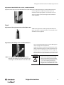
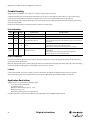
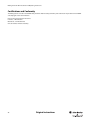
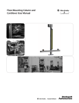
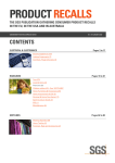
Muting Controller Box
Installation and Operating Instructions
Original instructions
R
Muting Controller Box Installation and Operating Instructions
Important User Information
Because of the variety of uses for the products described in this publication, those responsible for the
application and use of this control equipment must satisfy themselves that all necessary steps have been
taken to assure that each application and use meets all performance and safety requirements, including
any applicable laws, regulations, codes and standards.
The illustrations, charts, sample programs and layout examples shown in the guide are intended solely for
purposes of example. Since there are many variables and requirements associated with any particular
installation, Rockwell Automation does not assume responsibility or liability (to include intellectual property
liability) for actual use based upon the examples shown in this publication.
Rockwell Automation publication SGI-1.1, Safety Guidelines for the Application, Installation and
Maintenance of Solid-State Control (available from your local Rockwell Automation sales office), describes
some important differences between solid-state equipment and electromechanical devices that should be
taken into consideration when applying products such as those described in this publication.
Reproduction of the contents of this copyrighted publication, in whole or part, without written permission
of Rockwell Automation, is prohibited.
Throughout this manual we use notes to make you aware of safety considerations:
WARNING
IMPORTANT
ATTENTION
Identifies information about practices or circumstances that can cause an explosion in
a hazardous environment, which may lead to personal injury or death, property
damage, or economic loss.
Identifies information that is critical for successful application and understanding of
the product.
Identifies information about practices or circumstances that can lead to personal
injury or death, property damage, or economic loss. Attentions help you identify a
hazard, avoid a hazard, and recognize the consequences.
SHOCK HAZARD
Labels may be on or inside the equipment (for example, drive or motor) to alert people
that dangerous voltage may be present.
BURN HAZARD
Labels may be on or inside the equipment (for example, drive or motor) to alert people
that surfaces may reach dangerous temperatures.
It is recommended that you save this user manual for future use.
2
Original instructions
R
Muting Controller Box Installation and Operating Instructions
Contents
Reference Documents. . . . . . . . . . . . . . . . . . . . . . . . . . . . . . . . . . . . . . . . . . . . . . . . . . . . . . . . . . . . . . . . . . . . . . . . . . . . . . . . . . . . . . . 3
Introduction . . . . . . . . . . . . . . . . . . . . . . . . . . . . . . . . . . . . . . . . . . . . . . . . . . . . . . . . . . . . . . . . . . . . . . . . . . . . . . . . . . . . . . . . . . . . . . . 4
Wiring . . . . . . . . . . . . . . . . . . . . . . . . . . . . . . . . . . . . . . . . . . . . . . . . . . . . . . . . . . . . . . . . . . . . . . . . . . . . . . . . . . . . . . . . . . . . . . . . . . . . . 5
Operating . . . . . . . . . . . . . . . . . . . . . . . . . . . . . . . . . . . . . . . . . . . . . . . . . . . . . . . . . . . . . . . . . . . . . . . . . . . . . . . . . . . . . . . . . . . . . . . . . . 9
Muting Types. . . . . . . . . . . . . . . . . . . . . . . . . . . . . . . . . . . . . . . . . . . . . . . . . . . . . . . . . . . . . . . . . . . . . . . . . . . . . . . . . . . . . . . . . . . . . .12
Configuration and Diagnostic Tool. . . . . . . . . . . . . . . . . . . . . . . . . . . . . . . . . . . . . . . . . . . . . . . . . . . . . . . . . . . . . . . . . . . . . . . . . .14
Indication . . . . . . . . . . . . . . . . . . . . . . . . . . . . . . . . . . . . . . . . . . . . . . . . . . . . . . . . . . . . . . . . . . . . . . . . . . . . . . . . . . . . . . . . . . . . . . . . .16
Installation. . . . . . . . . . . . . . . . . . . . . . . . . . . . . . . . . . . . . . . . . . . . . . . . . . . . . . . . . . . . . . . . . . . . . . . . . . . . . . . . . . . . . . . . . . . . . . . .18
Mounting Stand . . . . . . . . . . . . . . . . . . . . . . . . . . . . . . . . . . . . . . . . . . . . . . . . . . . . . . . . . . . . . . . . . . . . . . . . . . . . . . . . . . . . . . . . . . .19
Adjustment . . . . . . . . . . . . . . . . . . . . . . . . . . . . . . . . . . . . . . . . . . . . . . . . . . . . . . . . . . . . . . . . . . . . . . . . . . . . . . . . . . . . . . . . . . . . . . .22
Trouble Shooting . . . . . . . . . . . . . . . . . . . . . . . . . . . . . . . . . . . . . . . . . . . . . . . . . . . . . . . . . . . . . . . . . . . . . . . . . . . . . . . . . . . . . . . . . .24
Application Restrictions. . . . . . . . . . . . . . . . . . . . . . . . . . . . . . . . . . . . . . . . . . . . . . . . . . . . . . . . . . . . . . . . . . . . . . . . . . . . . . . . . . . .24
Technical Data. . . . . . . . . . . . . . . . . . . . . . . . . . . . . . . . . . . . . . . . . . . . . . . . . . . . . . . . . . . . . . . . . . . . . . . . . . . . . . . . . . . . . . . . . . . . .25
Certifications and Conformity . . . . . . . . . . . . . . . . . . . . . . . . . . . . . . . . . . . . . . . . . . . . . . . . . . . . . . . . . . . . . . . . . . . . . . . . . . . . . .26
Reference Documents
GuardShield User Manual
MSR42 Control Module User Manual
GuardShield Safe 4 Safety Light Curtains User Manual
GuardShield Micro 400 Safety Light Curtains User Manual
MSR42 Configuration and Diagnostic Tool User Manual
Installation Instruction Mounting Column
User manual for any other safety device being connected to the muting controller box
Original instructions
R
3
Muting Controller Box Installation and Operating Instructions
Introduction
The Rockwell Automation Guardmaster muting controller box is a pre-wired enclosure using an MSR42 multi-function control module as
the muting control module. This muting enclosure has pre-wired M12 quick-disconnect connectors to accommodate the connection of
the Safe2/Safe4, Micro 400, or GuardShield POC and PAC safety light curtains. It also has pre-wired quick-disconnect connectors to
connect up to four Rockwell 42EF, 42JS, or other Rockwell sensors as well as an M8 quick-disconnect connector for a muting lamp.
ATTENTION
The GuardShield Type 2 and Safe 2 light
curtains may be used with the muting
controller. However, the use of Type 2
devices with Category 4 devices does not
improve the safety level of the safety circuit
above a Category 2. Make sure that a risk
assessment determines that a Category 2/
Type 2 level of safety is sufficient for the
application.
The Rockwell Automation Guardmaster muting box is supplied with flat brackets to mount this enclosure to a solid, flat surface or to the
Rockwell Automation aluminum two meter floor mounting stand (445L-AMSTD2M). This floor mounting stand is designed for one or two
500 mm aluminum posts (445L-AMSTDMUT) to be cantilevered to each side of the vertical floor stand allowing for two or four muting
sensors to be connected and positioned along their length. This mounting stand with one cantilever post is best for two sensor “L” type
muting applications and a two cantilever post configuration is best suited for two or four sensor “T” type muting. Both “L” and “T”
configurations are best suited for conveyorized muting applications.
The MSR42 multi-function safety control module allows up to four sensor muting, if the Micro 400 safety light curtain is used. Or for two
sensor muting if the Safe 2/Safe 4 or GuardShield safety light curtains are used.
The Rockwell Automation muting control box is designed in accordance with the technical specification TS/IEC 62046.
The Rockwell Automation muting control box is factory configured for two sensor muting using a Safe 2, Safe 4, or GuardShield safety
light curtain. Other muting configurations or safety light curtains will require the reprogramming of the MSR42 muting control module
using the optical interface (445L-AF6150).
The factory default configuration of the MSR42 muting control module is as follows:
•
•
•
•
Two sensor “T” type muting
Without monitored muting lamp
With manual start mode
Without EDM
Mute dependant override is active and configured as follows:
T(mdo) is 60 seconds
Configured muting times
t(sens) is 4 seconds
t(mute) is 5 minutes
t(msdel) is 50 ms
The response time of the factory configured muting box is 17.30 ms.
Muting is indicated by the illumination of a white lamp on the front cover of the muting box or an external muting lamp may be
connected to an M8 pico quick-disconnect connector located on the bottom of the muting box.
4
Original instructions
R
Muting Controller Box Installation and Operating Instructions
Muting Controller Box
(MSR42) (445L-AMUTBOX1)
Mounting Stand
(445L-AMSTD2M)
Light Curtains—POC or PAC—
(GuardShield Micro 400,
Safe 2, OR Safe 4)
Reflector
Cantilever
(445L-AMSTDMUT)
Muting Sensor
Floor Mounting Plate
(included with
mounting stand)
Figure 1: Muting System
Wiring
Connect muting components, power and output according the corresponding muting type picture below.
Two Sensor Muting with Safe 4
Figure 2: Wiring two sensor muting (T-Type or L-Type) with GuardShield Safe 4.
Original instructions
R
5
Muting Controller Box Installation and Operating Instructions
Four Sensor Muting with GuardShield Micro 400
Figure 3: Wiring four sensor muting (T-Type) with GuardShield Micro 400
ATTENTION
ATTENTION
If connecting the Micro 400 to the muting
box, the configuration of the MSR42 has to
be changed according to the Software and
Optical Interface section on page 14.
It is necessary to use the original shielded
Micro 400 patchcords (445L-AC8PCX (X is 1,
2, 3, 5, or 8 m)) to connect the Micro 400
transmitter and receiver to the muting
controller.
Not using these cables may cause a safety
risk.
6
Original instructions
R
Muting Controller Box Installation and Operating Instructions
Two Sensor Muting with GuardShield 440L
GuardShield 440L Rx
Tx Micro 400
Rx Micro 400
GuardShield 440L Tx
Control
Cabinet
Outputs
PWR
I/O
Rx-GS
Muting
Lamp
S1
Tx-GS/Tx-S4
S2
S3
Rx-S4
S4
Muting sensors
with reflectors
Figure 4: Wiring two sensor muting (T-Type or L-Type) with GuardShield 440L
ATTENTION
When using other safety devices in a muting
system, the configuration of the MSR42 must
be changed according to the Software and
Optical Interface section on page 14.
Muting of Laser Scanners or Other Safety Sensors
Figure 5: Two sensor muting of a laser scanner or other safety devices with PNP output
Original instructions
R
7
Muting Controller Box Installation and Operating Instructions
When using other safety devices in a muting
system, the MSR42 configuration must be
changed according to the Software and
Optical Interface section on page 14.
ATTENTION
Assignment
Pin Assignment
2
2
5
3
1
3
4
1
4-pin
5
6
5-pin
Assignment
Test
Pin3
GND
Pin4
Test
Pin5
Earth
GND
Earth
Assignment
4
4
Pin2
MSR42 Signal
24V
1
7
3
24V
Table 5: Connect GuardShield 440L or Safe 2 or Safe 4 transmitter
(Tx-GS/Tx-S4)
2
8
Pin1
8-pin
Cordset
889D-F8AB-x
MSR42 Signal
Pin1
MSR42 Signal
24V
24V
Pin2
OSSD 2
GPIO 4
Pin3
GND
GND
Pin4
OSSD 1
GPIO 3
Pin5
Earth
Earth
Table 6: Connector GuardShield Safe 2 or Safe 4 receiver (Rx-S4)
Pin1
Status Safety
Output
Info1
White
Pin2
24V
24V
Brown
Pin3
Earth
Earth
Green
Pin1
NC
NC
24V
24V
Assignment
MSR42 Signal
Pin4
Status Lockout
Info2
Yellow
Pin2
Pin5
OSSD1
OSSD1
Grey
Pin3
Earth
Earth
NC
NC
Pin6
OSSD2
OSSD2
Pink
Pin4
Pin7
GND
GND
Blue
Pin5
OSSD 1
GPIO 3
Red
Pin6
OSSD 2
GPIO 4
Pin7
GND
GND
Pin8
NC
NC
Pin8
Start
In1 (Start)
Table 1: Connector power (PWR/IO)
Assignment
Patchcord
889D-M5AC-x
MSR42 Signal
Table 7: Connector GuardShield 440L receiver (Rx-GS)
Pin1
Brown
Pin2
White
Pin 1
Tx-1
Pin3
Blue
Pin 2
Tx-2
Pin4
Black
Pin 3
Tx-3
Grey
Pin 4
Tx-4
Pin 5
Tx-5
Pin 6
Tx-6
Pin 7
Tx-7
Pin 8
Tx-8
Pin5
EDM - Start Release In 2
Table 2: Connector Outputs
Assignment
MSR42 Signal
Pin 1
24V
24V
Pin 2
Lamp
Lamp
Pin 3
NC
NC
Pin 4
NC
NC
MSR42 Signal
Table 8: Connector GuardShield Micro 400 transmitter (Tx Micro 400)
Assignment
Table 3: Connector Muting Lamp
Assignment
Assignment
MSR42 Signal
Pin 1
24V
24V
Pin 2
DO
NC
Pin 3
GND
GND
Pin 4
LO
GPIO1 (GPIO2, GPIO3, GPIO4)
Table 4: Connector muting sensor S1 (S2, S3, and S4)
MSR42 Signal
Pin 1
Rx-1
Pin 2
Rx-2
Pin 3
Rx-3
Pin 4
Rx-4
Pin 5
Rx-5
Pin 6
Rx-6
Pin 7
Rx-7
Pin 8
Rx-8
Table 9: Connector GuardShield Micro 400 receiver (Rx Micro 400)
8
Original instructions
R
Muting Controller Box Installation and Operating Instructions
Muting Lamp
The muting lamp warns an operator in the event that the light curtain is muted. Depending on the risk analysis, often a muting lamp,
monitored by the MSR42 control unit (controller box), signals the muting procedure. The size and the brightness of the connected lamp
must also be designed as required by the safety analysis.
By default the muting lamp is not monitored in the muting controller box. However, the muting lamp must be used (reference the MSR42
user manual for further information). To change the muting lamp to monitored, reference the “Configuration and Diagnostic Tool” user
manual.
If an error in the muting sequence has occurred, the muting lamp will blink (ca. 1 Hz), indicating that the muting condition has not been
initiated, or has been discontinued.
The plug “muting lamp” offers to connect an additional muting lamp to the controller box.
Muting Lamp
Meaning
Off
Safety light curtain active
On
Light curtain muted
Flashing
Error in muting sequence
Table 14: Muting lamp
Operating
The control of the muting is done with one spring return switch called Reset/Override. It triggers the start input of the MSR42 controller.
The control signal on the Quick-QD M12 connector “PWR I/O” – Pin 8 (Start) works in parallel to the key switch.
Key Switch, Reset/Override
Turn right (impulse)
Reset
Turn right (impulse)
Mute dependent override
Turn right (10 sec)
Power restart
Reset/override key switch on muting box is identical with the start signal from connector, PWR I/O — Pin 8 (Start)
ATTENTION
Before restarting the muting operation,
make sure all personnel are out of the
hazardous area.
Original instructions
R
9
Muting Controller Box Installation and Operating Instructions
Reset
The reset function switches on the OSSD safety outputs consider the safety light curtain is uninterrupted.
24V
Start
0V
> 0.1 s
24V
OSSD
0V
Figure 16: Reset function
Mute Dependent Override
An error in the muting signal sequence will discontinue the muting condition. If the safety light curtain is then interrupted the OSSD
outputs will switch off. This normally leads to a stoppage of the movement of the material. The muting lamp will flash.
For moving the material out of the protective field area in this situation (protective field interrupted), the start signal triggers the mute
dependant override function.
ATTENTION
The maximum activation time t(mdo)a for
this override function is set to one minute by
default. This time has to be considered on
risk analysis of the application.
The “Reset/Override” switch has to be
mounted at a location, where the dangerous
area can be overseen.
The mute dependant override function is
automatically terminated after the mute
dependant override time t(mdo) has
elapsed, or when the safety light curtain is
no longer interrupted.
a.
Mute dependent override time
24V
Start
0V
> 0.1 s
OSSD
Light
Curtain
24V
0V
max. t(m do)
24V
OSSD
0V
Figure 17: Mute dependent override function
Lockout and Restart
The following fault conditions will lead to a lockout:
• The connection to the Micro 400 safety light curtain emitter or receiver is interrupted.
• Defect in the electronics of Micro 400 light curtain or the MSR42 controller.
• Supply over- or undervoltage
• Error in EDM
A lockout is indicated with LED “Error Status” (= off ) and with the output signal “Lockout” of connector “PWR/IO” (Pin 4). On the Micro 400
light curtain it is indicated with the red blinking LED (emitter and receiver).
10
Original instructions
R
Muting Controller Box Installation and Operating Instructions
24V
Output
Status
0V
24V
Error
Status
0V
24V
Start
0V
> 10 sec
> 0.1 s
24V
OSSD
0V
Figure 18: Power-up function
The lockout mode may be reset by one of two methods:
• Power down, then Power up. If the fault is still present the module will lockout again.
• A start signal on switch “Reset/Override”
• A start signal on connector “PWR I/O” Pin 4
Assuming the cause of the lockout has been eliminated (from activating the “Reset/Override” switch for ten seconds), the controller starts
up. If the safety light curtain is interrupted, e.g. due a pallet, the controller goes into a safe off mode. The “Reset/Override” switch has to
be reactivated again to start the mute-dependent-override function (see Figure 18).
Muting Controller Box
(MSR42) (445L-AMUTBOX1)
Mounting Stand
(445L-AMSTD2M)
Light Curtains—POC or PAC—
(GuardShield Micro 400,
Safe 2, OR Safe 4)
Reflector
Cantilever
(445L-AMSTDMUT)
Floor Mounting Plate
(included with
mounting stand)
Muting Sensor
Figure 19: Muting System
Original instructions
R
11
Muting Controller Box Installation and Operating Instructions
Muting Types
The international standard IEC 62046 describes two- and four-sensor T- and L-type muting. The sensor positions recommended below are
taken from IEC62046 and IEC61496 (A.7). The light curtain should detect the material, not the carrier (pallet).
T-Type 2 Sensor
d3
d3
d4
Hazardous
Zone
d4
d5
h2
h1
d1
d2
Figure 20: The distance d5 should be as short as practicable in order to avoid persons entering the hazardous zone without being detected
when following immediately after the pallet or the transport system. The muting beam cross point has to be in the hazardous zone.
h1:
Lower height of safety protective field
h2:
Muting sensor height
The distances d1, d2, d3 and d4 has to be selected, that the
difference in timing is > 50 ms.
h2 > h1
h2 >= h1
d1, d2,
d3, d4:
d5: distance from the safety light curtain to the muting sensor
crossing point.
Distance light curtain — muting sensor
Muting sensor reflectors
T-Type 4 Sensor
d2
d2
d1
d3
d1
d3
d2
d2
h2
h1
h1:
Lowest beam of safety light curtain
h2:
Muting sensor height
d1 < 200 mm
d1:
Distance light curtain — muting sensor
d3 < 200 mm
d3:
Distance light curtain — muting sensor
d2 > 250 mm
d2:
Distance muting curtain — muting sensor
12
Recommended mounting position according to IEC 62046 F.2:
Original instructions
R
Muting Controller Box Installation and Operating Instructions
L-Type 2 Sensor
d2
d2
d1
d1
h2
h1
h1:
Lowest beam of safety light curtain
Recommended mounting position according to IEC 62046 F.2:
h2:
Muting sensor height
d1 < 200 mm
d1:
Distance light curtain — muting sensor
d2 > 250 mm
d2:
Distance muting sensor — muting sensor
h2 ≥ h1
Muting Function
Moving goods (e.g. pallet) through the muting station leads to the timing diagram of the left picture below. During the mute time
[t(mute)] the muting lamp is lit. Muting sensor S1 and muting sensor S2 must have a timing delay of at least >50 ms.
ESPE
Muting Sensor S1
Muting Sensor S2
Mute
t SENS
t ESPE
t ESPE
t SENS
t MUTE
Timing for 2 Sensor T-type (standard factory supplied configuration)
Original instructions
R
13
Muting Controller Box Installation and Operating Instructions
Configuration and Diagnostic Tool
Software and Optical Interface
The default configuration is set for two beam T-Type muting of a GuardShield Safe 2 or Safe 4 (445L) or a GuardShield (440L) safety light
curtain.
Other muting types can be selected with the configuration and diagnostic tool software and downloaded with the optical interface
(445L-AF6150). The software and manual are supplied with the optical interface or are available on www.ab.com (Product MSR42).
Muting Type
Safety Light Curtain
2 Beam, GS Safe
2 Beam, 2 Beam, 4 Beam, T-Type 2 or Safe
T-type
L-type
T-Type wEnable
4
Default
√
GS
Micro
400
GuardShield
(440L)
Other
Safety
Sensor
RightSight
VisiSight
Other
√
√
√
√
√
Default Setting
Configurable with
MSR42 safety
software &
download with
optical interface
√
√
Selectable
√
Selectable
√
Selectable
Muting Sensor
√
√
√
√
√
√
√
∗
√
∗
∗
√
√
√
∗
√
∗
∗
√
√
√
Comments
Table 24: Setting for the MSR42 muting controller
Inputs
Outputs
Safety
IN1
IN2
Info1
Info2
Stop delay
External Device
Monitor (EDM)
Default
Start
None
Safety Output
Lockout
No
No
Selectable
Test Input
Start EDM
Start Release
See MSR42 Safety
Software
See MSR42 Safety
Software
<120s
EDM
Start Release
Table 25: Settings for the muting controller (MSR42)
Additional Settings
M-Lamp
Monitored
Default
Selectable
no
yes/no
Mute Depend.
Override Active Muted Light Curtain
Time Settings
Light Curtain
Interrupt.
Monitored
t (sens)
t (espe)
t (mute)
t (mdo)
t (msdel)
4s
5s
5 min
60 s
0.05 s
yes
OSSD
yes
yes/no
OSSD GuardShield
Micro 400
yes/no
See MSR42 configuration manual
Table 26: Settings for the MSR42 muting controller
14
Original instructions
R
Muting Controller Box Installation and Operating Instructions
Table 27: MSR42 configuration and diagnostic software
Download with Optical Interface
In case the default configuration (see above) will not be used, the
created configuration has to be downloaded with the optical
interface (445L-AF6150); connected to the MSR42 control module.
Clip the suction head cap into the black fastener
Connect the USB plug into your computer
Start the configuration software
Create the desired configuration. Reference the
“Configuration and Diagnostic Tool” user manual.
Download the configuration (Menu File – download)
Original instructions
R
15
Muting Controller Box Installation and Operating Instructions
Indication
Safety Light Curtain
The green LED on the receiver light curtain indicates under normal operation if the protective field is uninterrupted. See corresponding
light curtain manual.
Emitter
POWER
GuardShield Safe 4, GuardShield Safe 2
Receiver
Power on
(orange)
POWER
Power on
(orange)
OK
Normal operation
(green)
Output active
(green)
TEST
Test input
(red)
Output inactive
(red)
OptiLink
(IR light)
OptiLink
(IR light)
Emitter
LED = green on
Normal operation
Receiver
LED = green on
Protective field is uninterrupted
LED = red on
Protective field is interrupted.
GuardShield Micro 400
LED = green on
Protective field is uninterrupted
LED = red on
Protective field is interrupted.
LED = Flashing red
Lock out condition
LED = Flashing green
Low light intensity
Note: If the LED is flashing green, optimal alignment has not
been attained. Continue adjusting the Micro 400 until a
solid green LED is visible.
Muting Sensor
Check the sensor manual for LED indication.
The yellow LED on the RightSight sensor indicates correct
alignment of an uninterrupted beam. If the orange LED is off, the
intensity is too low and the beam should be readjusted.
Muting Box
Three indicators showing the condition of the muting box.
Muting lamp
ATTENTION
16
off
white on
white flashing
Safety light curtain is active
Safety light curtain is muted
Muting sequence error
Output status off
green on
OSSD output = off
OSSD output = on
Error status
Lockout
ok
off
green on
The status output are driven from the MSR42 output info 1 and 2. The meaning of the indication can be
changed according to the configuration downloaded for the MSR42 (see Software and Optical Interface
section).
Original instructions
R
Muting Controller Box Installation and Operating Instructions
Muting System Examples
Product
Part Number
Description
Safe 4 PAC Light Curtain Example
Light Curtain
1x
445L-P4S3400YD
Safe 4 PAC 3 beam light curtain pair
Muting Box
1x
445L-AMUTBOX1
Muting Controller Box (MSR42)
Light Curtain Patchcord
2x
889D-F5ACDM-1
5 conductor M12 patchcord 1 meter, also offered in 5 and 10 meter lengths (2 required)
Muting sensor
2x or 4x
42EF-P2MPB-Y4
RightSight, Polarized Retro, Red, DC - 2 Complementary LO/DO Outputs, (PNP), 4-pin
Pico QD on 152 mm (6 in.) pigtail (2 or 4 sensors required) muting sensor patchcord
Muting sensor patchcord
2x or 4x
889P-F4ABPM-x
4 conductor M8 patchcord (x = 1, 2, 3, or 5 meter)
Muting sensor bracket
2x or 4x
60-2649
Muting sensor reflector
2x or 4x
92-39
Swivel/Tilt Bracket for RightSight sensors 2x or 4x 889P-F4ABPM-1
Reflector 76 mm (Bracket included in 445L-AMSTDMUT)
If external mute lamp is desired, a mute lamp option with right angle bracket is below
Muting lamp with bracket
1x
855E-24TL7
855E-BVMC
Muting lamp patchcord
1x
889P-M4AB-5
4 conductor M8 Pico patchcord, 5 meters
Connection cable power
(PWR/IO)
1x
889D-F8AC-x
x = 2, 5, or 10 meter
Connection cable outputs
1x
889D-M5AC-x
x = 2, 5, or 10 meter
Muting lamp with right angle bracket
GuardShield PAC Light Curtain Example
Light Curtain
1x
440L-P4A3400YD
GuardShield PAC 3 beam light curtain pair
Muting Box
1x
445L-AMUTBOX1
Muting Controller Box (MSR42)
Light Curtain Patchcord
1x
889D-F4ACDM-1
Transmitter patchcord 1 m, Straight, DC Micro M12-4 conductor
Light Curtain Patchcord
1x
889D-F8ABDM-5
Receiver patchcord 5 m, Straight, DC Micro M12-5 conductor
Muting sensor
2x or 4x
42EF-P2MPB-Y4
RightSight, Polarized Retro, Red, DC - 2 Complementary LO/DO Outputs, (PNP), 4-pin
Pico QD on 152 mm (6 in.) pigtail (2 or 4 sensors required) muting sensor patchcord
Muting sensor patchcord
2x or 4x
889P-F4ABPM-x
4 conductor M8 patchcord (x = 1, 2, 3, or 5 meter)
Muting sensor bracket
2x or 4x
60-2649
Muting sensor reflector
2x or 4x
92-39
Swivel/Tilt Bracket for RightSight sensors muting sensor patchcord
Reflector 76 mm (Bracket included in 445L-AMSTDMUT)
If external mute lamp is desired, one mute lamp option with right angle bracket is below
855E-24TL7
855E-BVMC
Muting lamp with bracket
Muting lamp patchcord
889P-M4AB-5
Muting stand
Muting cantilever
2x
445L-AMSTD2M
2x or 4x
445L-AMSTDMUT
Muting lamp with right angle bracket
4 conductor M8 Pico patchcord, 5 meters
Micro 400 Light Curtain Example
Light Curtain
1x
440L-P4E1200FP
30 mm Micro 400 light curtain pair, 1200 mm
Muting Box
1x
445L-AMUTBOX1
Muting Controller Box (MSR42)
Micro 400 patchcords
2x
445L-AC8PC1
8 pin M12 patchcord with filter, 1 meter, also offered in 3 meter and 5 meter lengths
Muting sensor
2x or 4x
42EF-P2MPB-Y4
RightSight, Polarized Retro, Red, DC - 2 Complementary LO/DO Outputs, (PNP), 4-pin
Pico QD on 152 mm (6 in.) pigtail (2 or 4 sensors required) muting sensor patchcord
Muting sensor patchcord
2x or 4x
889P-F4ABPM-x
4 conductor M8 patchcord (x = 1, 2, 3, or 5 meter)
Muting sensor bracket
2x or 4x
60-2649
Muting sensor reflector
2x or 4x
92-39
Swivel/Tilt Bracket for RightSight sensors muting sensor patchcord
Reflector 76 mm (Bracket included in 445L-AMSTDMUT)
Original instructions
R
17
Muting Controller Box Installation and Operating Instructions
Muting System Examples (continued)
Product
Part Number
Description
If external mute lamp is desired, one mute lamp option with right angle bracket is below
Muting lamp with bracket
1x
855E-24TL7
855E-BVMC
Muting lamp patchcord
1x
889P-M4AB-5
4 conductor M8 Pico patchcord, 5 meters
Optical interface
1x
445L-AF6150
Optical interface (can be reused for further configuration)
Muting lamp with right angle bracket
Installation
If mounting the Rockwell Automation Guardmaster muting box as a standalone muting box, it is best to locate this muting box adjacent
to the muting sensors and safety light curtain. The enclosure may be mounted to a smooth flat surface by using the brackets supplied
with the muting box.
It is also possible to mount the enclosure to the Rockwell Automation floor mounting stand (445L-AMSTD2M). This two meter stand kit
comes with a aluminum floor plate, hardware, and Installation instructions. Depending upon the muting system design, it may be
necessary to purchase one or two 500 mm aluminum post kits (445L-AMSTDMUT) that are designed to be cantilevered from the side of
the vertically mounted floor stand.
Mounting hardware (T-nuts, and screws) are included in the two meter stand and 500 mm post kits to mount the muting sensor, light
curtain and muting box1.
Mounting of the Muting Controller Box
Mount the brackets on the muting box.
Tighten the screws properly.
Determine where on the mounting stand the muting box will be
located.
Check for height position with respect to the cable wiring of the
light curtain, muting sensors and muting lamp.
Connectors should be positioned on the bottom side of the muting
box.
Premount the muting box with the T-slot nuts to the mounting
column.
Do not tighten the screws until the box is in right position.
Tighten the screws alternately.
1.
18
T-nuts and screws for:
Safety light curtain Safe4, Safe2, 445L-AF6145 for Micro 400, GuardShield 440L,
Muting sensor bracket 60-2649 (RightSight) and 92-39 Reflector
Muting box
Original instructions
R
Muting Controller Box Installation and Operating Instructions
Mounting Stand
Mounting Column (basic instructions, see installation instructions supplied with 445L-AMSTD2M kit)
Step 1: Assemble floor plate to two meter post.
Mount the mounting column onto the floor plate.
See mounting stand installation instruction
Check for front side positioning of the column (see picture). Check
the sliding nuts position for light curtain, sensor bar, and controller
box.
Step 2: Attach muting sensor post(s) according to desired muting type
Attach bars (e.g., two sensor muting)
Step 3: Attaching light curtain brackets
GuardShield Safe 2/Safe 4
T-slot nut and screws are included with the floor mounting column.
The mounting brackets are included with the safety light curtain.
Premount the mounting kits on the T-slot
Before mounting the light curtain, check for height position and
cable exit (bottom or top).
Original instructions
R
19
Muting Controller Box Installation and Operating Instructions
Step 4
GuardShield Micro 400
The Micro 400 light curtain is supplied with 180° adjustable
mounting brackets. The flat mounting bracket kit (445L-AF6145) is
sold separately. Before mounting, check for height and cable exit
position (bottom or top).
The 180° adjustable mounting brackets are included with the
safety light curtain. T-slot M4-nut and screws are included with the
floor mounting column.
Premount the brackets to the Micro 400 profile.
Attach Micro 400 brackets to the post slots using T-nuts provided.
GuardShield Micro 400 Profile Reinforced (specialty light curtains)
The GuardShield Micro 400 reinforced profile uses the same
mounting brackets (445L-AF6140) as the GuardShield Safe 4. They
are supplied with the light curtain.
T-slot nuts and screws are included with the floor mounting
column.
Before mounting, check for height and cable exit position (bottom
or top).
20
Original instructions
R
Muting Controller Box Installation and Operating Instructions
GuardShield Type 2/Type 4 (440L)
The mounting brackets for the GuardShield 440L are supplied with
the light curtain.
T-slot nut and screws are included with the floor mounting column.
Before mounting, check for height and cable exit position (bottom
or top).
Premount the bracket
Premount the light curtain with the supported screws.
Tighten the screws after aligning.
Note: Only one slot of the GuardShield bracket will fit into
the mounting stand channel.
Step 4
Mounting of the Muting Sensors
Before starting to mount the muting sensors, check the section for
the mounting position with respect to the muting type. Mount the
muting sensor according its instruction.
T-slot nut and screws for the RightSight bracket 60-2649 are
supported with the cantilever.
Check for good visibility of the sensor indicator LEDs.
Step 5
Mounting of the Retroreflectors
Check the Muting Types section on page 12 for the mounting
position for the chosen muting type.
T-slot nut and screws are provided with the cantilever.
Muting with GuardShield Micro 400
For muting a GuardShield Micro 400 safety light curtain use the safety software to create a configuration and download it to the MSR42
controller.
Two-Beam or Four-Beam Muting
The MSR42 offers two beam and four beam muting according to the Muting Types section (page 12). The controller box is delivered by
default with the two-beam T-type muting. Other muting configurations can be selected with the safety software and downloaded with
the optical interface.
Note: Four beam muting is only possible if the Micro 400 safety light curtain is used.
Original instructions
R
21
Muting Controller Box Installation and Operating Instructions
Adjustment
Step 6
Light curtain Rx
Light curtain Tx
Adjustment of the Safety Light Curtain
Position the emitter and receiver light curtain at the same height
on the mounting column.
Fully tighten the light curtain mounting screws.
Step 7
General
First, adjust the horizontal angle of the floor mounting plate.
Second, adjust the light curtain vertical axis (left-right) and vertical
front-back-axis of the stand. However, the lighting of the green LED
on the light curtain indicates that the protective field is
uninterrupted and the light curtain aligned.
Premount the column with the floor mounting plate on the
floor.
Adjust (with the floor plate adjustment screws) the position of
the mounting column after mounting a light curtain.
When the light curtain indicates uninterrupted protective
field, mount the mounting screws on the floor plate.
22
Original instructions
R
Muting Controller Box Installation and Operating Instructions
Adjustment of GuardShield Safe 4, Safe 2, or 440L GuardShield
Adjustment of the safety light curtain GuardShield Safe 4, GuardShield Safe 2, or GuardShield Type 2 or Bulletin 440L GuardShield:
Use the integrated laser alignment system (ILAS) for easy
verification. Touching the symbol turns the laser on or off.
The green indicator on the receiver light curtain confirms the
correct allignment.
Step 8
Adjustment of the Light Curtain GuardShield Micro 400
The Micro 400 light curtain is best aligned by LED indicators. A
green LED indicator on either the emitter or receiver light curtain
confirms the correct alignment.
Adjustment of the Muting Sensors and Retroreflectors
For the corresponding muting type, check the Muting Types
section on page 12 for sensor positions.
Tighten the cantilever screw when positioned at the correct
height and the muting sensors are at the proper distance to
the light curtain (see the Muting Types section on page 12).
Adjust the reflectors and muting sensors to each other. Check
the status LEDs on the opto-retroreflective sensor for correct
operation.
Note: The image shows the RightSight with reflector.
Normally, the muting sensor gets mounted on one
mounting bar and the reflectors on the other side.
ATTENTION
Original instructions
R
• A pallet should not interrupt the light
curtain nor the muting sensors. The light
curtain and the muting sensors should be
interrupted by the transported goods only.
• For a correct muting sequence, the
muting sensors must be interrupted from
the goods with a time difference of >50 ms.
23
Muting Controller Box Installation and Operating Instructions
Trouble Shooting
When the LED “Status Output” and “Status Error” are lit, the muting system is operating.
A simple functionality test can be performed interrupting each sensor for its own. Supposing that power is on, light curtain, muting
sensors and the muting lamp are connected. The function of each sensor can be checked with the sensor LED indicator.
When considering correct operation of the light curtain and muting sensors, the muting lamp will flash when interrupting one muting
sensor for a few seconds.
Check for the muting sequence according to Figure 3: Time for two sensor T-type.
Error Indications
Muting
Lamp
Output
Status
Error
Status
off
on
on
Operating, safety light curtain active
on
on
on
Operating, safety light curtain muted
x
off
on
Operating, OSSD output off
Reset
Make sure, that the safety light curtain and muting senors are operating and
uninterrupted
x
x
off
Lockout
Reset for ten seconds
Check cables and connections of the light curtains
See the Lockout and Restart in the Operating section on page 10.
Mute Sequence Error
Make sure, that the muting sensor and the safety light curtain are
uninterruupted.
Check alignment of the safety light curtain and muting sensors
Clean the muting sensors and safety light curtain
flashing
on
on
Possible Reason
Possible Solution
Error in Sequence
If an error in the muting sequence has occurred, the muting lamp will blink (ca. 1 Hz), indicating that the muting condition will not be
initiated, or has been discontinued.
Make sure, that the muting sensor and the safety light curtain are uninterrupted. Check alignment of the safety light curtain and muting
sensors. Eventually the muting sensors and safety light curtain have to be cleaned.
Lockout
A non-illuminated LED “error status” indicates a lockout as described in the Software and Optical Interface section on page 14.
The reason for the lockout can be analyzed with the optical interface 445L-AF6150 and the safety software (see page 14).
Application Restrictions
The application is not intended for the following usage:
• In an explosive environment (EX),
• In radioactive areas or
• Outside of a temperature range of 0 … 55°C.
• Operating range < 2.5 m
(depending on muting sensors and light curtain)
For further restrictions, see technical specification of the safety light curtain and MSR42 Safety Controller.
24
Original instructions
R
Muting Controller Box Installation and Operating Instructions
Technical Data
General data
Temperature range
Environment temp.: 0…+55°C (32…131°F); Stock temp.: -25…+70°C (-13…158°F)
Enclosure rating according EN 60529
IP65
Net weight
MSR42
Muting box
Cantilever floor mounting stand
Housing dimensions
111 x 22,5 x 125 mm (incl. plugs)
Certifications
According MSR42
Interfaces
Optical Interface
130 g
1.7 kg
5.7 kg
Weight and packaging
Dispatch packaging
MSR42
Muting box
Cantilever floor mounting stand
280x 200 x 70 mm
300x 200x 200 mm
Dispatch weight
MSR42
Muting box
Cantilever floor mounting stand
350 g
2.3 kg
6.5 kg
OSSD semi conductor outputs (PNP)
Voltage
UN - 2 V
Current Max
400 mA short-circuit protected and with cross-fault detection
Leakage current
IMAX Off ≤ 0.1 mA (CLOAD ≤ 3.3 uF)
Max. response time t(C) with UN protective mode
≤ 17.3 ms
Output S1-S4 (MSR42 GPIO1 – GPIO4)
Nominal voltage
UN – 2V (coded) (Short circuit protected)
Current max
100 mA (short-circuit protected)
Leakage current
IMAX Off ≤ 0.05 mA (CLOAD ≤ 100 nF)
Status Outputs (PNP), MSR42 Info 1, Info 2
Voltage
UN – 2V
Current max
100 mA (short-circuit protected)
Leakage current
IMAX Off ≤ 0.05 mA (CLOAD ≤ 4.7 uF)
Inputs (MSR42)
Power supply UN
+24V DC (EN 60204-1)
at 5% residual ripple
0.85…1.15 UN
Current consumption
Nominal: 70 mA; Rush-In current: max 1.7 A
Max. power consumption at max. supply voltage
2.1 W (semiconductor outputs unloaded)
Controller protection (external)
5 A slow
Control current into: IN 1, IN 2
2 mA each (min.) (in accordance with EN 61131-2)
Minimum voltage at: IN 1, IN 2
11V DC at activated controller (EN 61131-2)
Start pulse duration
Min.
Max.
50 ms
5s
Mute sensor time delay
> 50 ms
Test pulse duration (min.)
Response time x 2
Control current into: GPIO1 – GPIO4
7 mA
Safety Prevention Lamp
Minimum current at Lamp
8 mA with lamp switched on
0.9 A with lamp switched on
Safety Related Parameter
Probability of a dangerous failure per hour PFH
9.0 E-10 1/h
3.0 E-10 1/h
4.0 E-9 1/h
Original instructions
R
MSR42 Main M.
MSR45E
GuardShield Micro 400
25
Muting Controller Box Installation and Operating Instructions
Certifications and Conformity
The Muting Station is based on the MSR42 Safety Controller. Relevant safety conformity and certifications may be found on the MSR42
and safety light curtain documentation.
Please contact us for Technical Assistance:
In the U.S.: 1-440-646-5800
Outside U.S.: 001-440-646-5800
Visit our website: www.ab.com/safety
26
Original instructions
R
Muting Controller Box Installation and Operating Instructions
Original instructions
R
27
Muting Controller Box Installation and Operating Instructions
www.rockwellautomation.com
Power, Control and Information Solutions Headquarters
Americas: Rockwell Automation, 1201 South Second Street, Milwaukee, WI 53204 USA, Tel: (1) 414.382.2000, Fax: (1) 414.382.4444
Europe/Middle East/Africa: Rockwell Automation, Vorstlaan/Boulevard du Souverain 36, 1170 Brussels, Belgium, Tel: (32) 2 663 0600, Fax (32) 2 663 0640
Asia Pacific: Rockwell Automation, Level 14, Core F, Cyberport 3, 100 Cyberport Road, Hong Kong, Tel: (852) 2887 4788, Fax: (852) 2508 1846
Publication 10000127397 Ver 01 July 2011
Copyright 2011 Rockwell Automation, Inc. All rights reserved.
28
Original instructions
R