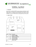
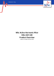
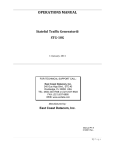
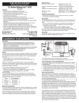
1
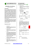
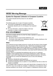
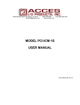
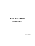
Offers the option of 9-pin d-sub shell con-
ECD485IC USERS MANUAL
nector (AT style) or large capacity (2.5mm²)
ISOLATED RS-232 TO RS-485 CONVERTER
compression screw terminals, giving maxi-
FOR 2 AND 4-WIRE RS-485 WITH GROUND WIRE
mum flexibility in installation in panels and
1. INTRODUCTION
terminal boxes.
RS-485 has become one of the most common
9-pin female “DCE like” ports allow use of
data communication standards in "open" multi-
ribbon cables from 9-pin computer ports.
vendor automation projects. More robust than
600 watt transient suppresser diodes are
RS-232 and more flexible than RS-422, it allows a
installed on isolated ports
single master device to communicate with mul-
(600w for 1ms
with less than 1psec response to over-
tiple slave devices.
voltage)
1.1. Product Over-view
For robust operation, the ECD485ic is an essen-
1.2. What is RS232?
+V
tial component of your industrial applications.
RS-232 is an inter-
--V
It provides the following unique combination of
face standard -
features:
not
a
0V
data
01010011
ASCII "I"
Safely converts between EIA standard RS-
communication
232 and RS-485 signals.
standard. This means it can only go short dis-
Isolates and protects the data signals and
power supply grounds.
tances and has very limited driving power. It
provides full-duplex, point-to-point data transfer
between two devices. The signal ground is in-
With floating grounds, RS-232 cable runs up
cluded as one of the wires, so it is very
to 50m can be guaranteed with quality,
susceptible to damaging ground loops. Data is
low-capacitance cable like Beldon 1422A
transmitted as a voltage polarity relative to the
at 42pF/m. (RS-232 requires < 2500pF per
common signal ground. For example, here is
signal wire.)
the signal for an ASCII character 'I'. When sig-
Over 2500v optical isolation between RS232 and RS-485 (5kv test isolation) and
2500v galvanic isolation between RS-485
and the power supply (3kv test isolation).
The full isolation 3-port model also has isolation between RS-232 and power supply.
nal voltage > +3v, then the data is a binary 0.
When signal voltage < -3v, then the data is a
binary 1.
A voltage signal between -3v and
+3v is undefined. An idle line without data will
be in the binary 1 state. This voltage signal referenced
to
a
shared
ground
is
quite
susceptible to noise, plus the existence of the
For rapid troubleshooting, LED indicators for
the TX, RX, and power status.
ground wire leads to grounding and surge
problems.
Wide power supply range (9 to 36vdc) with
spike protection allows use with 9v, 12v,
15v, 24v power supplies or direct from 12v
or 24v battery systems.
ECD485ic User Manual
www.ecdata-tech.com
1 of 6
1.3. What is RS-485?
RS-485 is a half-duplex data communication
2. FUNCTIONAL
DESCRIPTION
A
standard which can be use for point-to-point or
multi-drop applications.
B
It uses twisted wire
pairs. Data is transmitted by a differential volt-
01010011
ASCII "I"
age signal. The two wires in a pair are not a
loop -- both are '+' signals sourcing current to a
third "virtual" ground conductor. For example,
here is the differential signal for an ASCII character 'I'.
Though labels vary from vendor to
vendor, one wire of the pair is often labeled A
and the other B. Data is represented by the
relative voltage of A to B. When VA < VB, then
the data is a binary 1. When VA > VB, then the
data is a binary 0. An idle line without data will
be in the binary 1 state. This differential voltage
signal is quite robust and not susceptible to
noise or minor shifts in signal reference ground.
1.4. Two or Four Wire RS-485
One wire
pair is used as a bi-directional bus, first transmita
"request"
"response".
and
A power conditioning circuit steps 9-36vdc
down to a stable, filtered 5vdc. High isolation
DC-to-DC converters convert this to one or two
isolated 5vDC supplies. In all models (-2p and 3p), RS-485 port-A has a fully isolated supply. In
the case of full 3-of-3 port galvanic isolation
models (option -3p), RS-232 port-B also has an
isolated supply, while in the partial 2-of-3 port
galvanic isolation models (option -2p), RS-232
2-wire RS-485 is strictly half-duplex.
ting
2.1. Isolated Power Supply
then
receiving
a
Many industrial products support
both 2 or 4 wire RS-485. Providing terminals for
4-wire, they allow external jumpers to short the
two A signals and two B signals for 2-wire.
port-B is powered directly from the filtered 5vdc
without isolation.
2.2. Optical Isolation for Data Signals
Digital opto-couplers are used to move the
data signals between the two sides of the converter. These are superior to the more common
analog opto-couplers, as they add little distor-
4-wire uses two twisted wire pairs - one for
tion and therefore support high baud rates.
transmit and one for receive. The Tx pair is used
The isolated power supplies and optical data
by a master device to communicate with the
signals complete the galvanic isolation re-
slave devices, and the Rx pair is used by the
quired.
slave devices to respond. 4-wire RS-485 is more
robust than 2-wire with low quality cable or
high environmental noise. It also reduces the
data communication interrupt load on the
slave devices.
2.3. RS-485 Bus Transceiver
Line interface driver/receiver chips convert the
field signals to standard TTL-level signals. The
full EIA/RS-485 specification is meet by using
SN75176 compatible chips. Since 2-wire RS-485
Note that there is a special form of 2-wire
is a bi-directional bus, it requires the transmit-
RS-485 which allows an optional 2nd wire pair
ter/receiver circuit to switch between transmit
to be used as a control (RTS) signal to manage
and receive as appropriate - the ECD485ic uses
repeaters in the system.
ECD485ic User Manual
www.ecdata-tech.com
2 of 6
an effective method to do this with 100% soft-
Unfortunately, there are two common logic
ware transparency.
systems. Computer systems treat 0v and 5v as
0 and 1 respectively, while the most common
2.4. User Indication
RS-485
chips
label
(and
general
telecommunications) treat 0v and 5v as 1 and
0 respectively.
To avoid the issue, many
vendors select other naming conventions.
3.2. Determining terminal names
The face of the ECD485ic is shown above.
Green LEDs (Pwr-A & Pwr-B) light showing isolated power is available from the isolated DCto-DC converters. Yellow LEDs (Rcv-A, Txd-A &
Rcv-B, Txd-B) light when data is received and
transmitted on the respective port (RS-485 is
port A, RS-232 is port B).
EC Data names it's A/B terminals as “-“ and “+”
respectively - since when measured by a volt
meter, the “A” terminal of an idle asynchronous
RS-485 data line will be a lower voltage than
the “B” terminal.
Another common naming
conventions is to label them as "X"/"not X",
where X is a name like DAT or BUS, and the "not"
2.5. Signal Conditioning
condition is marked either by a bar over the
For normal operation, the ECD485ic has 6
name or a leading "*". An example would be
jumpers installed to terminate and bias the RS-
"DAT+/DAT-" or "DAT/*DAT".
485 interface. These are only removed when
and "not" terminals correspond to "A", but ven-
more than two (2) units of ECD485ic are con-
dors are free to label them opposite here as
nected to the same RS-485 wire pair.
well.
For
example, if 4 units of ECD485ic connect to a
wire pair, at least 2 of them must have all 3
jumpers removed.
Both ports have transient
suppression diodes rated at 500w or higher.
3. DETERMINING RS-485 TERMINAL NAMES
Due to a lack of naming conventions, wiring
multi-vendor RS-485 devices often involves wiring "apples" to "oranges". It may require some
bench-top experimentation. While this sounds
bad, it is often required when integrating multivendor systems. Neither the RS-485 nor the RS232 interface can be damaged by reverse wir-
Generally the "--"
A direct method to determine the absolute
A/B terminals would be helpful. If your asynchronous device outputs a voltage when idle,
then the terminal with the higher voltage is "+".
Unfortunately, most devices will show no measurable
voltage
difference
between
their
terminals; slave devices are normally in receive
mode and do not affect the terminal voltage.
4. INSTALLATION
4.1. Making Standard RS-232 Cables
The ECD485ic has one 9-pin female connector
which looks like a 9-pin “modem” or DCE port.
ing or short-circuits to ground.
cable w
9-pin m
3.1. Per EIA-485
Txd
Rxd
EIA-485 defines the labels "A" and "B" to be
Gnd
rdc485ic
used as follows: Voltage of A shall be negative
in respect to B for a binary 1. Sounds simple?
Cable A : host with 9-pin DTE port
ECD485ic User Manual
www.ecdata-tech.com
3 of 6
RS-485 2-wire Cable
Standard RS-232 interface devices cannot be
damaged by reverse wiring or short-circuits to
ground.
But be warned some low-cost devices
use transistors to approximate an RS-232 signal
and this built-in protection may not be there.
Cable C : host with 25-pin DCE port
4.2. Plan your RS-485 wiring (Screw Terminal
Models - cc & cd )
For 2-wire RS-485, all "+" terminals connect to
one wire of the pair, and all "-" terminals to the
other wire. As a convention, EC Data suggests
choosing the darker wire (or solid color) for "+"
and lighter color (or striped) for "-". Since the
bus is bi-directional, all terminals "+" and "-" both
transmit and receive when appropriate.
Re-
member, RS-485 is NOT a loop.
RS-485 2-wire Cable
With the 9-pin D-sub shell option for the RS-485,
the same 2 or 4-wire signals are available on
pins 2, 3, 5 and 1, 2, 3, 4, 5 respectively. The
diagram above shows how to write a cable
between 2 units of ECD485ic. To facilitate making multi-drop cables each signal (but ground)
is available on 2 pins. Pin #1 (R+) is also on pin
#6, pin #2 (T+) is also on pin #7, pin #3 (T-+) is
On the ECD485ic, the top screw terminals
are physically labeled D+A, D-A, Gnd-A. On
the removable terminals this is labeled T+, T-,
R+, R-, SG. Note that the important thing is the
“+” and “-“ in the names. The D+A top terminal
and the T+ terminal are internally connected,
as are the D-A and T-. With 2-wire RS-485 you
can easily use 2 wire lugs on the Port A side great when you are doing a multi-drop bus
also on pin #8, and pin #4 (R-) is also on Pin #9.
It is also critical that the Signal Ground be
properly connected - you void your warrantee
if you do not connect this ground properly. If
your RS-485 bus does not have the 3rd ground
wire, then you should at least connect the Signal Ground (Gnd-A or SG) of RS-485 to the
nearest device’s digital ground.
4.4. Placing your bus terminators
without stubs.
485ic-01
It is also critical that the Signal Ground be
properly connected - you void your warrantee
if you do not connect this ground properly. If
your RS-485 bus does not have the 3rd ground
wire, then you should at least connect the Sig-
V+
D+
D-
SN75176B
0v-
Pin 1
5v+
Gnd
Jumpers
nal Ground (Gnd-A or SG) of RS-485 to the
nearest device’s digital ground.
SN75176B
Pin 1
MAX232EPE
4.3. Plan your RS-485 wiring (D-Sub Shell Models
- dd )
Pin 1
Jumper location
Each RS-485 segment requires a 120 ohm terminating resister at each end - assuming your
ECD485ic User Manual
www.ecdata-tech.com
4 of 6
5. TECHNICAL SPECIFICATION
ohms.
5.1. RS-485 port Description
T-Bias+
T-Term
T-BiasR-Bias+
R-Term
R-Bias2-Wire
4-Wire
cable has a characteristic impedance of 120
5.1.1.
2-wire Signals; D+A, D-A, and Gnd-A,
D+B, D-B, and Gnd-B
5.1.2.
Duplex;
matic.
5.1.3.
Line Voltage; -7v to +12v permits 7vdc
ground difference between devices.
5.1.4.
Bias; 470
pull-up (D+A, D+B) 470
pull-down (D-A,D-B) jumper selectable.
5.1.5.
Bus Termination;
able.
5.1.6.
Official maximum Bus Length; 1000m
per EIA-485, 500m per ISO 8482
5.1.7.
Practical maximum Bus Length; 3000m
with high-quality cable and other conditions.
5.1.8.
Maximum Speed; At least 115Kbps
Detail of jumpers
4.5. Planning the panel wiring
Power Supply: The ECD485ic (9 to 36vdc) is fully
protected from reverse wiring and will sustain
no damage. The ECD485ic (5vdc +- 5%) model
is partially protected and if a fuse is installed in
the V+ supply wire, should not sustain any
damage.
RS-485 Fuses: RS-485 field wires should be
half duplex. direction auto-
120
jumper select-
protected by 250mA fuses. RS-485 interface ICs
are internally protected from short-circuits.
5.2. Isolation
These fuses protect the system from over-
5.2.1.
Power Supply, between input supply
and data signals; full galvanic isolation;
3kV test voltage
5.2.2.
Power Supply, between input supply
and data signals; full galvanic isolation;
3kV test voltage
5.2.3.
Data, between RS-485 port A and port
B; optical isolation; 5kV test voltage
5.2.4.
Encapsulant (if ordered): 14,000v per
mm
7v, this disregards that RS-485 can work up to
5.2.5.
Overall rating at least 2500v
+12 volts. Clamping at too low of a voltage
5.3. Power Supply
can lead to the RS-485 drivers operating at
5.3.1.
5v Model; Supply of 4.75v to 5.25v
(175mA average)
5.3.2.
9-36v Model; 1.2watt (at 24vdc about
50mA)
voltages caused by mis-wiring - for example
wiring 110vac to the bus.
RS-485 Lightning Protection: If required, the
RS-485 field wires should be protected by standard lightning protection devices.
EC Data
suggests 15v or 16v surge protection.
While
many venders suggest clamping surges to 6v or
near short-circuit conditions and driving at the
full current. This can cause over-heating of device and/or power supply.
4.6. Physical installation
The unit mounts on a standard DIN rail as listed
in the specification.
ECD485ic User Manual
www.ecdata-tech.com
5 of 6
5.4. Environmental
5.4.1.
Ambient operating temperature; 0C to
+60C
5.4.2.
Ambient storage temperature; -40C to
+100C
5.4.3.
Relative Humidity; 10 to 95% RH, non
condensing
5.4.4.
Casing; fungus and termite resistance;
Good.
5.4.5.
Casing;
flame
characteristics:
self-
extinguishing.
5.5. Mechanical Dimensions
5.5.1.
Height; Width; Depth (See drawing).
5.5.2.
Weight; 130g.
5.5.3.
Terminal Capacity;
2.5mm strand (12 AWG)
4.0mm solid (12 AWG).
5.5.4.
Mounting Rail;
DIN EN 50022 (35mm "symetrical")
DIN EN 50025 (32mm "asymetrical")
Note: it fits best on the DIN 50022 style
rail.
ECD485ic User Manual
93 (3.7)
79 (3.1)
www.ecdata-tech.com
25 (1.0)
EN 50 022 - 7.5mm
EN 50 035
EN 50 022 - 15mm
6 of 6